

Page 1
8 Point Relay Expansion Interface Modules
Module Relais d'interface
Relais-Schnittstellenmodule
Moduli di interfaccia di Relay
Módulos de interface de Relés
(Cat 1492-XIM24-8R, -RXIM24-8R, -XIM120-8R)
WARNING
AVERTISSEMENT
WARNUNG
AVVERTENZA
ADVERTENCIA
To prevent electrical shock, disconnect from power source before installing or servicing.
Avant le montage et la mise en service, couper l'alimentation secteur pour éviter toutes décharges.
Vor Installations- oder Servicearbeiten Stromversorgung unterbrechen, um Elektroschocks zu vermeiden.
Per prevenire infortuni, togliere tensione prima dell’installazione o manutenzione.
Desconéctese de la corriente eléctrica, antes de la instalación o del servicio, a fin de impedir sacudidas eléctricas.
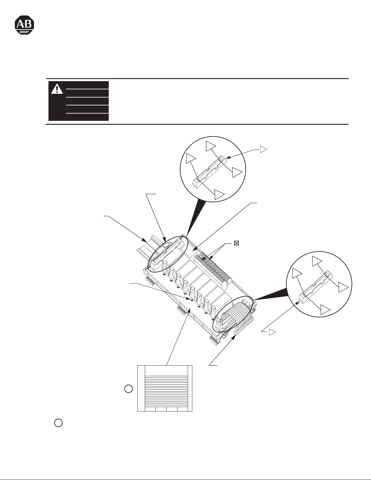
35 mm DIN Rail
199-DR1
199-DR4
1492-DR7
Status Indicator Relay Active
Voyant d'état de Relais Actif
Statusanzeigerelais Aktiv
Relay Indicatore di Stato Attivo
El Relé del Indicador de Estado Está Activo
1492-EAJ35
33
1
Relay Module Expansion Connector
= Connector Pin
= Broche de connexion
= Steckerstift
2
34
= Pin del connettore
= Pasador de conector
Module Identification Area.
Identification du module.
Modulkennzeichnungsbereich
Area per l'identificazione del modulo
Area de identificación del módulo.
= Field-side Terminals
= Borne exterieure
= Feldseitiger Terminal
= Terminale lato-campo
= Terminal de campo
A1
B1
2
34
33
1
Adhesive Label Card. Provides terminal wiring identification.
1
Carte étiquette adhésive. Identifie le câblage des bornes.
Aufklebbare Etiketten zur Kennzeichnung der Klemmenverdrahtung.
Scheda etichette adesive. Fornisce l'identificazione del cablaggio dei terminali.
Tarjeta de etiquetas adhesivas. Proporciona identificación de cableado del terminal.
PN-23154
DIR 40063-396 (Version 05)
Printed in U.S.A.
Relay Module Expansion Connector
= Connector Pin
= Broche de connexion
= Steckerstift
= Pin del connettore
Connection Cable
= Pasador de conector
Câble de connexion
Verbindungskabel
1
Cavo di connessione
Cable de conexión
Page 2
Module
Installation / Removal
Montage / Retrait
Installation / Entfernen
Montaggio / Smontaggio
Instalación / Extracción
1492-N90
3.5-4.5 lb-in
(0.38-0.50 Nm)
0.32 in
(8 mm)
#22-#12 AWG
(0.2-4 mm2)
Cu only
Cu seulement
nur Cu
Solo Cu
Cu solamente
Removable Terminal Block
Installation / Removal
Montage / Retrait
Installation / Entfernen
Montaggio / Smontaggio
Instalación / Extracción
3.5-4.5 lb-in
(0.38-0.50 Nm)
0.32 in
(8 mm)
#22-#12 AWG
(0.2-4 mm2)
Cu only
Cu seulement
nur Cu
Solo Cu
Cu solamente
H
1
Applies to modules with fixed and
removable (R) terminal block
Relay Expander Matrix
Matrice d'extension de relais
Relaiserweiterungsmatrix
Matrice espansore di relay
Matriz del expansor de relés
2
W
Applies to modules with
removable terminal block plugs (1492-RXIFM_)
I/O Module
Module E/S
E/A-Modul
Modulo I/O
Módulo de E/S
1746-OA16
1746-OB16
1746-OB32
1746-OB16E
1746-OB32E
1746-OBP16
1756-OA16
TC-ODA161
1756-OB16E
TC-ODD161
1756-OB32
TC-ODD321
1769-OA16
1769-OB16
1769-OB32
1769-OB32T
1771-OAD
1771-OBD
1771-OBN
1794-OB16
1794-OB16P
1794-OB32P
1492-XIM24-8R
1492-RXIM24-8R
1492-XIM120-8R
Can have up to 3 expandable modules depending upon master used.
Possibilité de 3 modules extensibles selon le maître utilisé
Kann je nach verwendetem Master bis zu 3 erweiterbare
Module aufweisen.
Possono avere un massimo di 3 moduli espandibili a seconda del
master usato.
Puede tener conectados hasta 3 módulos expansibles, según el
dispositivo maestro que se utilice.
Can have one expandable module per master.
Possibilité d'un seul module extensible par maître
Kann ein erweiterbares Modul je Master aufweisen.
Possono avere un modulo espandibile per master.
Puede tener conectado un solo módulo expansible por cada
dispositivo maestro.
Supports Removable Terminal Block (RTB) plug. Compatible screw style plug,
1492-RTB12N (Pkg. qty. 2). Compatible push-in style plug 1492-RTB12P (pkg. qty. 2).
Order plugs separately.
Cable is limited for use within the control panel unless it is run through conduit.
Cable is ITC (Instrumentation Tray Cable) rated.
1
2
PN-23154
DIR 40063-396 (Version 05)
(2)
Page 3

Pinout
Brochage
Anschlußbelegung
Disposizione dei piedini
Esquema de pins
Terminal Identification Convention
Convention d’identification des bornes
Klemmenbezeichnungskonvention
Convenzioni per l’identificazione dei morsetti
Convención de identificación del terminal
9
7
5
1492-XIM24-8R
1492-RXIM24-8R
1492-XIM120-8R
CJ
IN
(Continued)
CJ
OUT
1
2
3
4
6
5
7
8
9
10
20
24
28
30
32
31
34
33
14
12
13
16
11
15
18
17
1492-XIM24-8R
1492-RXIM24-8R
1492-XIM120-8R
CJ
IN
~
16
12
8
6
4
3
2
1
27
28
~
~
~
~
~
~
~
~
~
~
~
~
~
~
~
TB
A1
A2
K0
A3
A4
A5
K1
A6
B1
K2
B2
B3
B4
K3
B5
B6
B7
B8
K4
B9
B10
K5
B11
B12
A7
K6
A8
A9
A10
K7
A11
A12
30
31
32
25
26
29
24
23
22
21
20
19
18
17
15
14
13
11
10
I/O Wiring Data
NOTICE
Wiring information for your I/O module, AIFM module and cable (e.g. wiring diagram and pinouts)are available online at www.rockwellautomation.com/en/e-tools.
To obtain information follow this procedure.
1) In the Catalog Number BOX at the above online site type in the catalog number of the IFM, AIFM, etc. module you are using and click on Submit.
2) At the next screen displayed, click on the Modify key (lower left of screen).
3) Click on the areas that indicate NO SELECTION and enter your specific configuration information (e.g. I/O platform, I/O MODULE, ETC.).
NOTE: To obtain the wiring diagram, you must select th Pre-Wired Cable Connector selection.
4) Configure your 1492 cable by filing in the NO SELECTION areas.
5) Click on the ACCEPT key for the configured 1492 cable. At the next screen click on ACCEPT for the 1492 module.
6) The next screen (Configuration Results) displays the results of your specific configuration. The "supplementary Documents" column contains I/O wiring information
for the configuration (e.g. I/O Wiring Diagrams).
PN-23154
DIR 40063-396 (Version 05)
(3)
Page 4

700-HK36 _ _
Relay Contact Rating
Spécification du Contact à Relais
Relaiskontakt-Nennwerte
Classificazione Contatti di Relay
Capacidad Nominal del Contacto de Relé
Electrical Ratings
Rated Thermal Current (I
Rated Insulation Voltage (Ui) 250V IEC, 300V UL/CSA
Contacts Inductive VAC
)
th
Inductive VDC
Resistive
Make, Break and Continuous
1-Pole, 1 CO, SPDT - 16A
120VAC AC-15, 6.2 A
240VAC AC-15, 3.1 A
230VAC 0.55 kW 1-Phase
24VDC DC-13, 5.0 A
125VDC DC-13, 0.2 A
250VDC DC-13, 0.1 A
230VAC AC-1, 16 A
277VAC
30VDC DC-1, 12 A
B300 Pilot Duty, 3 A
1/3 HP (0.24 kW) 1-Phase
B300 Pilot Duty, 1.5 A
3/4 HP (0.55 kW) 1-Phase
R300 Pilot Duty, 0.22 A
R300 Pilot Duty, 0.11 A
16 A General Use
10 A, Resistive
Electrical Life (AC Loads) versus Contact Life
7
10
6
10
Cycles
5
10
048
700-HK36 SPDT Maximum DC1 Breaking Capacity
Electrical Life (DC Loads) versus Contact Life
20
10
6
4
2
1
0.2
DC Breaking Current (A)
0.1
20 60 100
· When switching a resistive load (DC1) having voltage
and current values under the curve, an electrical life
of > 100 x 103 can be expected.
· In case of inductive loads (DC13), the connection of a
diode in parallel with the load will permit a similar
electrical life as for a DC1 load. Note: the release
time for the load will be increased.
700-HK36 SPDT
Resistive Load - cos = 1
Inductive Load - cos = 0.4
Resistive Load
140 180 220
DC Voltage (V)
12 16
(A)
Minimum Permissible Contact Ratings
Maximum Module Current
· 10 Amps per relay output
Maximum continuous current for two adjacent relays is 12 Amps.
·
Le courant permanent maximum pour deux relais adjacents est de 12 A.
Der maximale Dauerstrom für zwei nebeneinanderliegende Relais beträgt 12 A.
La corrente continua massima per due relè adiacenti è di 12 ampere.
La corriente continua máxima para dos relés adyacentes es de 12 A.
Replacement Relays
· 24VDC Control (Coil) Voltage: 700-HK36Z24
120VAC Control (Coil) Voltage: 700-HK36A1
·
PN-23154
DIR 40063-396 (Version 05)
300mW (5V / 60mA or 60V / 5mA) for Silver Contacts)
(4)
Page 5

Specifications
Spécifications
Technische Daten
Specifiche
Especificaciones
Catalog No.
Référence
Bestell-Nr.
N. Catalogo
Referencia
1492-XIM24-8R
1492-RXIM24-8R
1492-XIM120-8R
Catalog No.
Référence
Bestell-Nr.
N. Catalogo
Referencia
1492-XIM24-8R
1492-RXIM24-8R
1492-XIM120-16R
For transients > 600 Vp use a UL recognized suppression device rated at 2.5 kV withstand.
Pour des transitoires > 600 Vp utilisez un dispositif de suppression certifié UL à 2,5 kV nominal de tenue.
Für Einschaltstöße > 600 Vp verwenden Sie einen UL anerkannten Entstörer, der bewertet wurde bei 2,5 kV standzuhalten.
Per transitori > 600 Vp usare dispositivo di soppressione riconosciuto da UL capace di sopportare 2,5 kV.
Para transitorios > 600 Vp use un dispositivo de supresión reconocido UL clasificado con 2,5 kV.
Voltage
Tension
Spannung
Tensione
Voltaje
20-26 VDC
20-26 VDC
96-132 VAC
Maximum Recurring Peak Voltage
Tension de crele réurrente maximale
Maximale periodische Hochstspannung
Tensione massima di cresta ricorrente
Voltaje de cresta iterativo máximo
Indicator Circuit Current
Courant circuit voyants
Strom, Anzeigeschaltkreis
Corrente circuito indicatori
Intensidad del circuito de
indicadores
p
600 V
Operating Temperature Range
Plage températures de fonctionnement
Betriebstemperaturbereich
Limiti temperatura di funzionamento
Rango de temperatura de funcionamient
2.0 mA 0° C - 60° C
Humidity
Humidité
Feuchtigkeit
Humedad
Umidità
5 - 95%
Approx. Shipping Weight
Poids d'embarquement approximatif
Ungefähres Versandgewicht
Peso approssimativo del carico
Peso aproximado al momento de
embarque
1.18 lb.
(536 g.)
Dimensions
Dimensions
Abmessungen
Dimensioni
Dimensiones
6.30 in. (160 mm) W
3.27 in. (83 mm) H
2.78 in (70.5 mm) D
Standards
Normes
Standards
Standard
Estándares
cULus (File: E113724, Guide No.: NRAQ)
CE: Compliant for all applicable directives
FM Class 1 Div 2 Groups A, B, C and D
Temperature Rating T3C = 60°C
(J.I. 3000590, all except relay modules)
Non-condensing
Sans condensation
Nicht kondensierend
Senza condensa
sin condensación
Add 0.39 in. to the width dimension for 1492-Rxx type modules.
SURGE SUPPRESSION follow the literature recommendations of the PLC module being used.
SUPPRESSION DES SURTENSIONS se trouve à la suite de la littérature qui contient les recommandations relatives au module PLC utilisé.
ÜBERSPANNUNGSSCHUTZ Bitte beachten Sie die Dokumentationsempfehlungen für das jeweils benutzte SPS-Modul.
Per la SOPPRESSIONE DEI PICCHI TEMPORANEI, seguire le istruzioni riportate nella documentazione in dotazione al Modulo PLC utilizzato.
SUPRESIÓN DE SOBRETENSIÓN, siga las recomendaciones indicadas en la documentación del módulo PLC respectivo.
PN-23154
DIR 40063-396 (Version 05)
(5)
Page 6

Reference Publications: Refer to 1770-4.1 and appropriate PLC I/O module installation manual.
PN-23154
DIR 40063-396 (Version 05)
Printed in U.S.A.
 Loading...