

Page 1
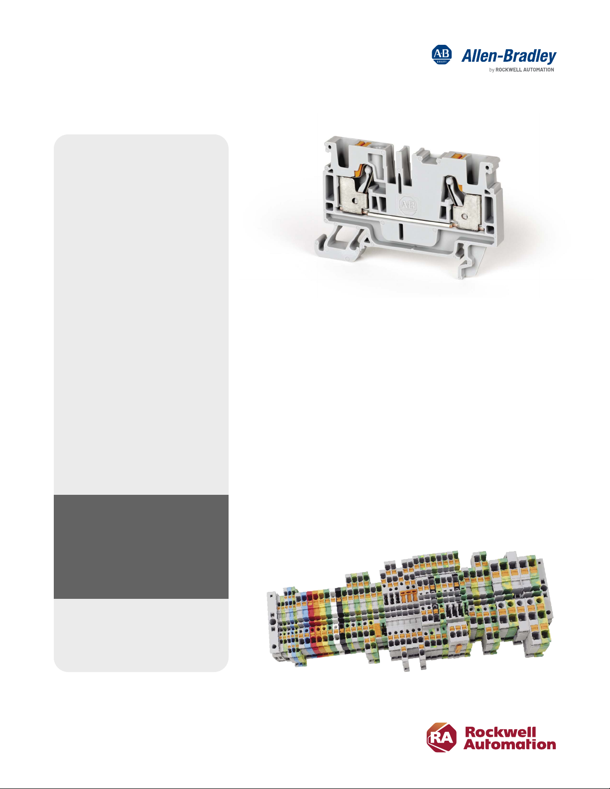
Bulletin 1492-P Push-in Terminal Blocks
Dramatic Time Savings and Improved Reliability
Features and Benets
• ONE-hand, ONE-second insertion
• No strand breakage or turned
back strands
• Low insertion force
• No retightening
• Easy-to-see terminals from the front
• Universally-located test points for fast
inspection and easy commissioning
• Plastic actuators for shock prevention
• Application-driven designs (power
distribution and sensor/signal blocks)
• No torque values needed to install
or double check
• Quick reference guide for easy
ferrule selection
• Marker areas located on the front and
sides with only four marker card types
needed for the entire product line
This innovative push-in connection technology oers dramatic time
savings by creating wiring eciency. The 1492-P Push-in terminal blocks
provide improved wiring accuracy and reliability insuring a quality
connection that requires no double checking.
When using an automated ferrule machine, installation can be up
to 65 percent faster than screw-type terminal block connections –
a 26 second savings per terminal block. That’s a saving of over seven
hours for every 1,000 terminal blocks connected. Not only is productivity
vastly increased, but the resulting connections eliminate the vibration
failure mode of screw terminals. The push-in connections signicantly
exceed UL pull-out standards.
65% reduction in labor –
saving over seven hours per
1,000 terminal blocks installed
Bulletin 1492-P Push-in terminal blocks oer panel builders, OEMs, and
other high-volume users cost-savings – not only in the form of increased
wiring speed, but also through eliminating connection adjustments and
torque-checking of screws. They are available in a wide range of standard
and application specic oerings, including a unique control power
distribution terminal block.
Page 2
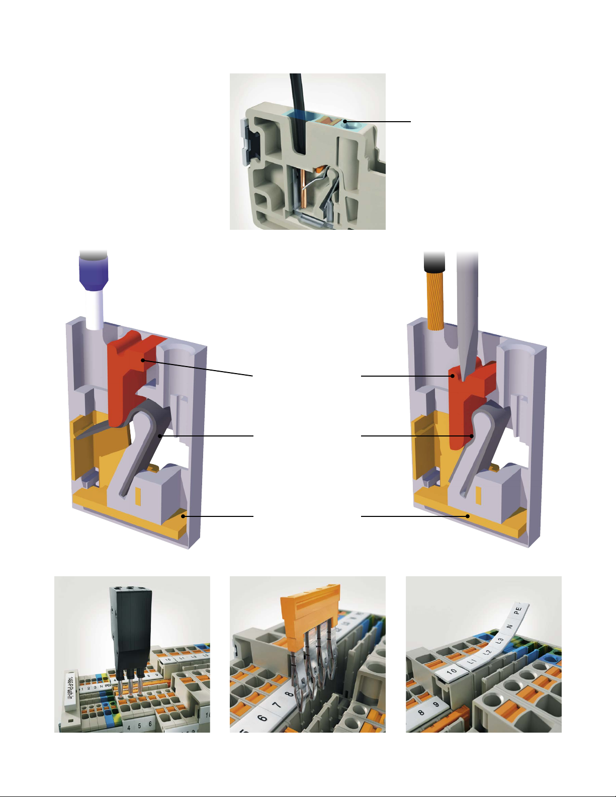
Push-in Technology
Approximate area
shown cut away below
Solid and ferrule:
Direct insertion
without tools
Stranded:
Press actuator
to open clamp
then insert wire
Actuators allow
insertion and removal
of all wire types
Steel clamp holds
wire onto current
bar connection
Copper for conductive
components
Easy verication testing with individual terminal test points. Multiple distribution congurations available with
two isolated jumper channels.
Compatible with Allen-Bradley ClearMultiprint,™
ClearPlot® and ClearMark™ marking systems.
Page 3
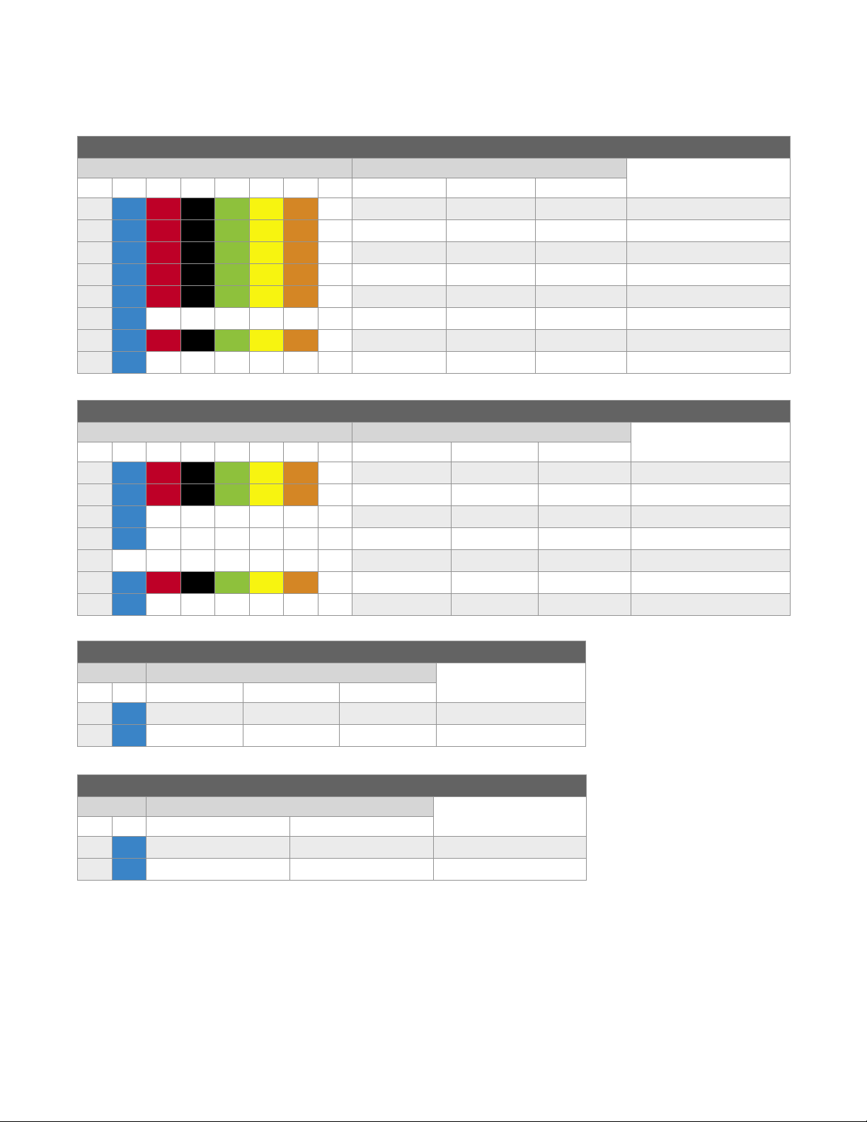
Oerings
A wide range of product and accessories are available, with eight colors and accepting wire sizes from 6-28 AWG
Universal / Standard Terminal Blocks
Single Level Feed-Through
(1)
Color
-B -RE -BL -G -Y -OR -W 2 Wire 3 Wire 4 Wire
Catalog Number
1492-P2 1492-P2T 1492-P2Q 26-14 AWG (1.5 mm2)
1492-P3 1492-P3T 1492-P3Q 28-12 AWG (2.5 mm2)
1492-P4 1492-P4T 1492-P4Q 26-10 AWG (4.0 mm2)
1492-P6 1492-P6T 22-8 AWG (6.0 mm2)
1492-P10 20-6 AWG (10.0 mm2)
– – – – – – 1492-P10T 20-6 AWG (10.0 mm2)
1492-P16 18-6 AWG (16.0 mm2)
– – – – – – 1492-P16T 18-6 AWG (16.0 mm2)
Multiple Level Feed-Through
(1)
Color
-B -RE -BL -G -Y -OR -W Double Level Three Level Four Level
Catalog Number
1492-PD3 28-12 AWG (2.5 mm2)
1492-PD3C
(3)
– – – – – – 1492-PT3 28-12 AWG (2.5 mm2)
– – – – – – 1492-PT3C
– – – – – – – 1492-PQ3
1492-PD4 26-10 AWG (4.0 mm2)
– – – – – – 1492-PD4C
(3)
(2)
(2)
Wire Range
(Rated Cross Section)
Wire Range
(Rated Cross Section)
28-12 AWG (2.5 mm2)
(3)
28-12 AWG (2.5 mm2)
(4)
28-12 AWG (2.5 mm2)
26-10 AWG (4.0 mm2)
Disconnect
(1)
Color
-B 2 Wire 3 Wire 4 Wire
Catalog Number
(2)
Wire Range
(Rated Cross Section)
1492-PKD3 1492-PKD3T 1492-PKD3Q 28-12 AWG (2.5 mm)
1492-PKD4 26-10 AWG (4.0 mm2)
Flex Plug-in
(1)
Color
-B Single Level Double Level
Catalog Number
(2)
Wire Range
(Rated Cross Section)
1492-P31P 1492-PD32P 28-12 AWG (2.5 mm2)
1492-PD32PC
(1) Available in gre y as the standard co lor. To order oth er colors add a sux t o the catalog numbe r. For exam ple, the catalog nu mber would be
1492-P3-B for a blue 1492-P3 termi nal block.
(2) Ground ing terminal bloc ks available in all siz es. To order a grouding te rminal block add a “G” to th e catalog number.
For examp le, the catalog numb er would be 1492-PG4Q for a gr ounding version o f 1492-P4Q.
(3) The “C” in the cata log number design ates a commoning bar m eaning the upper and l ower circuits are c onnected.
(4) The 1492-PQ3 includes a si ngle ground conne ction on the lowes t level.
(3)
28-12 AWG (2.5 mm2)
Page 4

Oerings
Accessory Plug-in
(1)
Color
2 Wire 3 Wire 4 Wire
Catalog Number
Wire Range
(Rated Cross Section)
1492-P3P 1492-P3PT 1492-P3PQ 28-12 AWG (2.5 mm2)
Fuse
Color Catalog Number
Voltage Rating
Non-Indicating
600V AC/DC 10…36V AC/DC 30…70V AC/DC 60…150V AC/DC 100…250V AC/DC
With LED for Blown Fuse Indication
1492-PFB4 1492-PFB424 1492-PFB448 1492-PFB4120 1492-PFB4250 26-10 AWG (4.0 mm2)
(1) Available in gre y as the standard co lor. To order oth er colors add a sux t o the catalog numbe r. For exam ple, the catalog nu mber would be
1492-P3-B for a blue 1492-P3 termi nal block.
(2) Ground ing terminal bloc ks available in all siz es. To order a grouding te rminal block add a “G” to th e catalog number.
For examp le, the catalog numb er would be 1492-PG4Q for a gr ounding version o f 1492-P4Q.
(3) The “C” in the cata log number design ates a commoning bar m eaning the upper and l ower circuits are c onnected.
(4) The 1492-PQ3 includes a si ngle ground conne ction on the lowes t level.
Universal/Standard Distribution Blocks
Fuse
Wire Range
(Rated Cross Section)
The 1492-P6D and 1492-P16D feed-in terminal blocks allow power to be distributed to the output terminal blocks.
Use center jumpers to connect to the output terminal blocks as shown.
1492-CJP2-*
1492-P6D
1492-P2
* Available in multiple pole versions.
1492-P3
1492-CJP2-*
1492-CJP3-*
1492-P2
1492-P16 D
1492-P3
1492-P16 D
1492-P4
1492-CJP3-*
1492-CJP4-*
1492-P6
1492-CJP6 -*
Page 5

Control Power Distribution Blocks
Colored actuators make it easy
to distinguish between the
positive and negative potentials
Up to 6 connection
points on the output
distribution terminals
3
Power is
distributed
to output
distribution
terminals
Block Type
Standard 1492-P6PD2S-1B
Standard 1492-P6PD2S-1RE
with Grounding
Standard 1492-P6PD2E-6B
Standard 1492-P6PD2E-6RE
Standard 1492-P6PD2S-1B1RE
with Grounding
Standard 1492-P6PD2E-3B3RE
1
Power is
supplied
to feed-in
terminals
2
Using
jumpers
Catalog Number
Start (Feed-in) End (Output)
(1)
(1)
(3)
(3)
1492-PG6PD2S
1492-P6PD2S-1RE1G
(1)
(1)
(1)
(2)
(2)
(2)
Wire Range
(Rated Cross Section)
22-8 AWG (6.0 mm2)
22-8 AWG (6.0 mm2)
22-8 AWG (6.0 mm2)
26-14 AWG (1.5 mm2)
26-14 AWG (1.5 mm2)
22-8 AWG (6.0 mm2)
22-8 AWG (6.0 mm2)
26-14 AWG (1.5 mm2)
Catalog Number
Block Type
Standard 1492-P10PD3S-1B
Standard 1492-P10PD3S-1RE
with Grounding
(3)
Start (Feed-in) End (Output)
(1)
(1)
1492-PG10PD3S
(1)
Standard 1492-P10PD3E-5B
Standard 1492-P10PD3E-5RE
Standard 1492-P10PD3S-1B1RE
with Grounding
(3)
1492-P10PD3S-1RE1G
(2)
(2)
Standard 1492-P10PD3E-2B2RE
(1) Shape/Size Cong uration #1: (+/-) on separate te rminal blocks
(2) Shape/Size Co nguration #2: (+/-) integrated into a s ingle terminal blo ck
(3) Not grounde d to the Din Rail. This is a f unctional ear th ground that allow s you ground the minu s potential of the powe r supply to 0 V.
Wire Range
(Rated Cross Section)
20-6 AWG (10.0 mm2)
20-6 AWG (10.0 mm2)
20-6 AWG (10.0 mm2)
(1)
(1)
28-12 AWG (2.5 mm2)
28-12 AWG (2.5 mm2)
20-6 AWG (10.0 mm2)
20-6 AWG (10.0 mm2)
(2)
28-12 AWG (2.5 mm2)
Page 6

Control Power Distribution Blocks
1492-P10PD4E-KD
Block Type
Start (Feed-in) End (Output)
Standard 1492-P10PD4S-1B
Standard 1492-P10PD4S-1RE
with Grounding
(3)
1492-PG10PD4S
1492-P10PD4E-FB* 1492-P 10PD4 E-1B1FB*
Catalog Number
(1)
(1)
(1)
Standard 1492-P10PD4E-1B
Standard 1492-P10PD4E-1RE
Standard 1492-P10PD4E-KD
Standard 1492-P10PD4E-FB
Standard 1492-P10PD4E-FB24
Standard 1492-P10PD4E-FB48
Standard 1492-P10PD4E-FB120
Standard 1492-P10PD4E-FB250
Standard 1492-P10PD4S-1B1RE
with Grounding
(3)
1492-P10PD4S-1RE1G
(2)
(2)
Standard 1492-P10PD4E-1B1FB
Standard 1492-P10PD4E-1B1FB24
Standard 1492- P10PD4E-1B1FB48
Standard 1492-P10PD4E-1B1FB120
Standard 1492-P10PD4E-1B1FB250
(1)
(1)(4 )
(1)( 5)
(1)
(1)( 6)
(1)( 6)
(1)( 6)
(1)( 6)
(2)(5)
(2)(6)
(2)(6)
(2)(6)
(2)(6)
Wire Range
(Rated Cross Section)
20-6 AWG (10.0 mm2)
20-6 AWG (10.0 mm2)
20-6 AWG (10.0 mm2)
26-10 AWG (4.0 mm2)
26-10 AWG (4.0 mm2)
26-10 AWG (4.0 mm)
26-10 AWG (4.0 mm)
26-10 AWG (4.0 mm)
26-10 AWG (4.0 mm)
26-10 AWG (4.0 mm)
26-10 AWG (4.0 mm)
20-6 AWG (10.0 mm)
20-6 AWG (10.0 mm)
26-10 AWG (4.0 mm)
26-10 AWG (4.0 mm)
26-10 AWG (4.0 mm)
26-10 AWG (4.0 mm)
26-10 AWG (4.0 mm)
(1) Shape/Size Cong uration #1: (+/-) on separate te rminal blocks
(2) Shape/Size Co nguration #2: (+/-) integrated into a s ingle terminal blo ck
(3) Not grounde d to the Din Rail. This is a f unctional ear th ground that allow s you ground the minu s potential of the powe r supply to 0 V.
(4) Includes knife disconnect/isolation
(5) Includes non indicating fuse holder
(6) Includes LED indicating fuse holder
* Available in n on-indicatin g and LED indicating . LED indicating is ava ilable in 24, 48, 120 and 250V AC/DC .
Page 7

Sensor/Signal Blocks
Sensor
Signal
+
–
Signal
–
Signal
PE
–
Actuator
Actuator
(1)
(2)
Signal 1
Signal 2
+
–
Sensor
(3)
Signal
+
–
PE
Colored ac tuators make
it easy to di stinguish
between the positive
and negative potentials.
Sensor
(1) Shape/Size Conguration #1 (2) Shape/Size Conguration #2
Sensor/Signal
Catalog Number
Block Type
Standard 1492-PS2-2
with Grounding 1492-PSG2-3
(1) Shape/Size Cong uration #1: (+/-) on separate te rminal blocks
(2) Shape/Size Co nguration #2: (+/-) integrated into a s ingle terminal blo ck
(3) Not grounde d to the Din Rail. This is a f unctional ear th ground that allow s you ground the minu s potential of the powe r supply to 0 V.
2 Circuit 3 Circuit 4 Circuit
(1)
1492-PS2-3
(1)
(1)
1492-PS2-4
1492-PSG2-4
Accessories
Plug End BarrierCenter Jumpers
(3) Shape/Size Conguration #3
(Rated Cross Section)
(2)
(3)
26-14 AWG (1.5 mm2)
26-14 AWG (1.5 mm2)
Plug Coding Element
Wire Range
Test Plugs
Plug Locking
Element
Plug Protective
Plugs (Start, Middle, End)
Cover
End Barriers
Page 8

Ferrule
Ferrules allow a stranded wire to act as a solid wire, so it can
be inserted into the push-in terminal blocks without tools.
Various hand-held or automated crimp tools are available,
depending on the volume of terminations needed.
In addition to the dramatic productivity advantages when
ferrules are used with push-in terminal blocks, they also
provide enhanced connection integrity and safety.
For specic information on which Panduit ferrules to use
with individual Bulletin 1492-P Push-in Terminal Blocks,
consult Appendix sections in Publication 1492-TD017.
Specications
A cylind rical tube of tin -coated copper (wi th or without an
insulated c ollar) that can be cri mped onto the end of a wi re.
UL/CSA Voltage Rating
UL/CSA Current Rating 10…62 A
Wire Range (Rated Cross Section)*
Density
Housing Temperature Range
Material Flammability Rating UL94 V0
Colors
Certications CE, UL, CSA, ATEX, IECEX, DNV GL
* North A merican wire rang e per NEC Table 310-16 using 75 °C and 90 °C stran ded Copper wire.
600V AC/DC,
300V AC/DC,
150V AC/D C
#28…6 AWG
(1.5…16 mm2)
87…2 5 p cs/ ft
(285…83 pcs/m)
-76 …+266 ° F
(- 60 …+130 °C)
Standard: Grey
Grounding Block: Green/Yellow
Available in some products:
Red, Blue, Black, Green, Yellow,
Orange and White
Connect with us.
Allen-Bradley, ClearMark, ClearMultiprint, ClearPlot and Expanding human possibility are trademarks of Rockwell Automation, Inc.
Trademarks not belonging to Rockwell Automation are property of their respective companies.
Publication 1492-PP014B-EN-P – May 2020 | Supersedes Publication 1492-PP014A-EN-P – April 2018
Copyright © 2020 Rockwell Automation, Inc. All Rights Reserved. Printed in USA.
 Loading...