

Page 1
Fused Field Wire Conversion Module for Modicon B814-108 or B840-108
to 1756-OX8I
(Cat 1492-CM800-LD015)
10000021918 (Version 01)
Printed in Germany
Local language (French, Italian, German & Spanish) versions of this document can be downloaded by going to www.ab.com.
In the left margin click on Publications Library and Literature Library. In the Search Area (right margin), Search by Catalog
Number and in the Search box type in the catalog number of the conversion system component.
I. Module Description
The 1492-CM800-LD015 conversion module provides field wire signal conversion from a Modicon® B814-108 or
B840-108 , 8-pt relay output to a ControLogix 1756-OX8I , 8-pt relay output module. The conversion module
provides the mating connections to the B814-108 or B840-108 swing-arm (terminal block) with the attached field wires.
It routes those signals, via its 40-pin connector and a 1492-CABLEY pre-wired cable to compatible terminals of the
1756-OX8I. To maintain the fusing functionality of the B814-108 and B840-108 output modules the conversion module
provides a mechanical fuse for each of the 8 converted output points (refer to the Wiring Diagrams on pages 2 and 3).
II. Module Installation
The 1492-CM800-LD015 conversion module must be installed in a 1492 conversion base-plate and cover-plate assembly. The installation of the module into the assembly is explained in the Installation Manual that ships with the conversion
assembly. For a list of compatible assemblies refer to Appendix A.
III. Conversion Module Compatibility Matrix
This is the cable length in meters and tenths of meters (e.g. 015 = 1.5 meters). Recommended cable
length is 003 (00.3 meters).
40-Pin Connector for 1492-CABLE
Y
Mating Connector for
B800 Terminal Block
Conversion Module Compatible 800
Output Module
Compatible 1756
Output Module
Required 1492 Cable
1492-CM800-LD0015 B814-108 1756-OX8I 1492-CABLE
Y
1492-CM800-LD0015 B840-108 1756-OX8I 1492-CABLE
Y
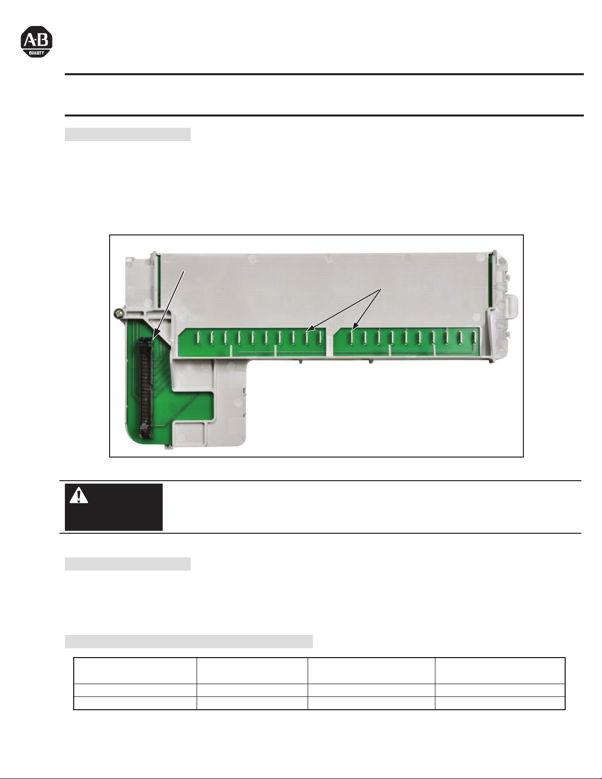
1492-CM800-LD015 Conversion Module
De-energize and lockout any and all power to all I/O field devices connected to the Modicon 800 I/O
housing, and the power to the 800 I/O housing itself. Ensure all power is de-energized and locked out to
any device in the control cabinet where the conversion is to be performed. Ensure work is performed by
qualified personnel.
WARNING
Refer to conversion module Specifications Section: Maximum Operating Voltage
Page 2
(2)
10000021918 (Version 01)
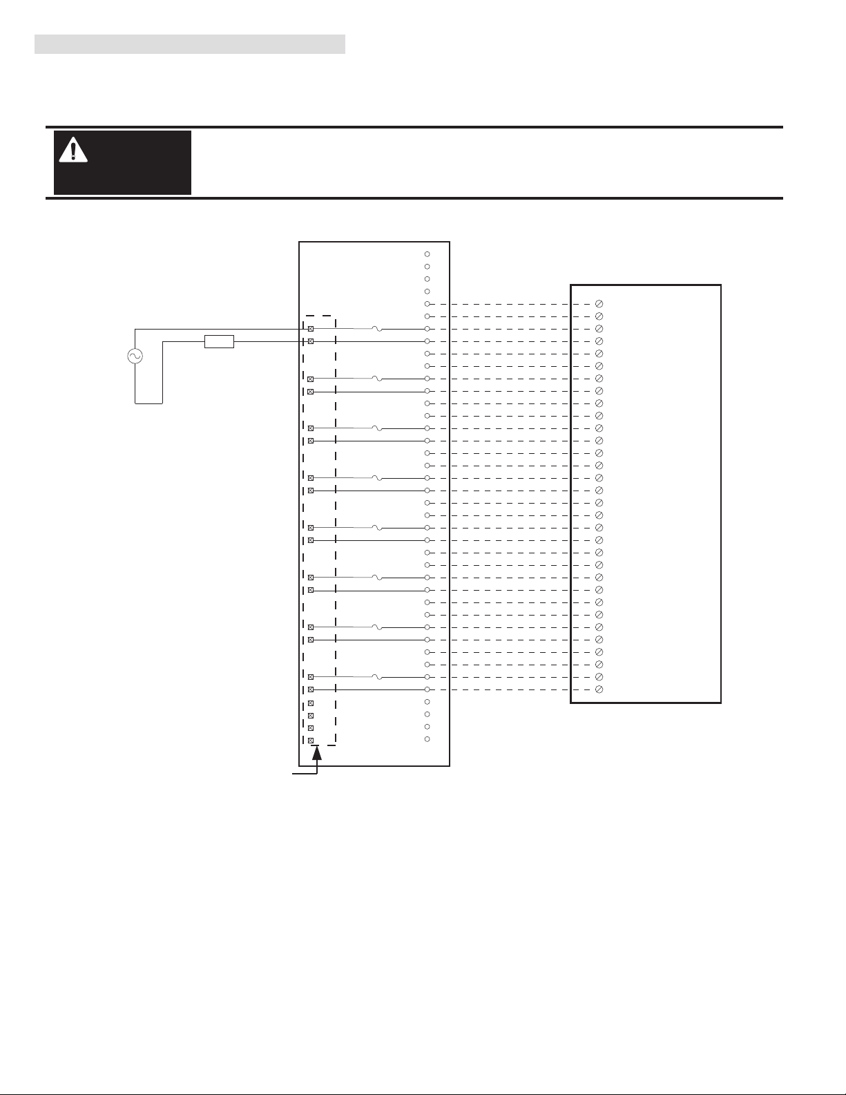
IV. Conversion Module Wiring Diagram
The following diagram shows the connections from the existing B814-108 and B840-108 swing-arm, through the conversion module, 1492 cable and to the 1756-OX8I output module. The diagrams can be used as an aid in possible system
troubleshooting.
1756-OX8I
1492-CABLE003Y
1492-CM800-LD015
Conversion: B814-108 to 1756-OX8I with 1492-CM800-LD015
B814-108 Swing Arm
Conversion Module Installation and Application Considerations
The B814-108 relay module resistive current limits versus 1756-OX8I limits are as follows: (NOTE: for switching and inductive
current and voltage ratings, refer to the modules Installation Manual)
B814-108 1756-OX8I w/ 1492-CABLE003Y
a) Current/Point
3A Cont, 2A Switching 960VA or 150W DC 2A @ 30V DC/125V AC
The B814-108 is fused per output point. The 1756-OX8I is NOT fused. The 1492-CM800-LD015 provides a 5x20mm fuse
per 1756-OX8I point. Fuse rating for this configuration is 2 Amps.
The 1492-CABLE003Y current is limited to 2A per pin.
The B814-108 allowed using a circuit board jumper to configure each relay output for N.O. or N.C. operation (N.O. default),
but only one set of field terminals was provided on the module. The 1492-CM800-LD015 conversion module is set for N.O.
relay operation. If the N.C. contact of the 1756-OX8I relay module is required, it may be accessed by modifying the wiring at
the module’s swing-arm (terminal block).
Refer to your B814-108 and 1756-OXI Installation Manual wiring schematics and diagrams. Ensure 1756 output module
ratings are not exceeded. [Reference Doc: 41170-782 (Version 03)]
1
2
3
4
1
5
2
6
3
7
4
8
6
9
7
10
8
11
9
12
11
13
12
13
15
14
16
16
17
17
18
19
19
18
20
14
15
21
20
22
23
24
25
26
27
28
29
30
31
32
33
35
36
5
37
10
38
39
40
34
Output 1
Output 2
Output 3
Output 4
Output 5
Output 6
Output 7
Output 8
Not Used
Not Used
Output 1A
Output 2A
Output 3A
Output 4A
Output 5A
Output 6A
Output 7A
Output 8B
Output 1B
Output 2B
Output 3B
Output 4B
Output 5B
Output 6B
Output 7B
Output 8A
LOAD
L1
L2
Not Used
Not Used
OUT-0 N.C.
2
1
OUT-0 N.O.
4
3
OUT-1 N.C.
6
5
OUT-1 N.O.
8
7
OUT-2 N.C.
10
9
OUT-2 N.O.
12
11
OUT-3 N.C.
14
13
Orange
Blue
White/Black
Red/Black
Green/Black
Orange/Black
Blue/Black
Black/White
Red/White
Green/White
Blue/White
Black/Red
White/Red
Orange/Red
Blue/Red
Red/Green
OUT-3 N.O.
16
15
OUT-4 N.C.
18
17
OUT-4 N.O.
20
19
OUT-5 N.C.
22
21
OUT-5 N.O.
24
23
OUT-6 N.C.
26
25
OUT-6 N.O.
28
27
OUT-7 N.C.
30
29
Orange/Green
Black/White/Red
White/Black/Red
Red/Black/White
Green/Black/White
Orange/Black/White
Blue/Black/White
Black/Red/Green
White/Red/Green
Red/Black/Green
Green/Black/Orange
Orange/Black/Green
Blue/White/Orange
Black/White/Orange
White/Red/Orange
Orange/White/Blue
OUT-7 N.O.
32
31
L1-0
L1-0
L1-1
L1-1
L1-2
L1-2
L1-3
L1-3
L1-4
L1-4
L1-5
L1-5
L1-6
L1-6
L1-7
L1-7
There are several key application considerations and system specifications (bottom of drawing) when
using these components (conversion module, cable and output module). Read and understand these
considerations before installation. In addition, refer to the current draw requirements of the existing
loads for this configuration to ensure they are within the current ratings of the 1756 output module.
WARNING
Page 3
(3)
10000021918 (Version 01)
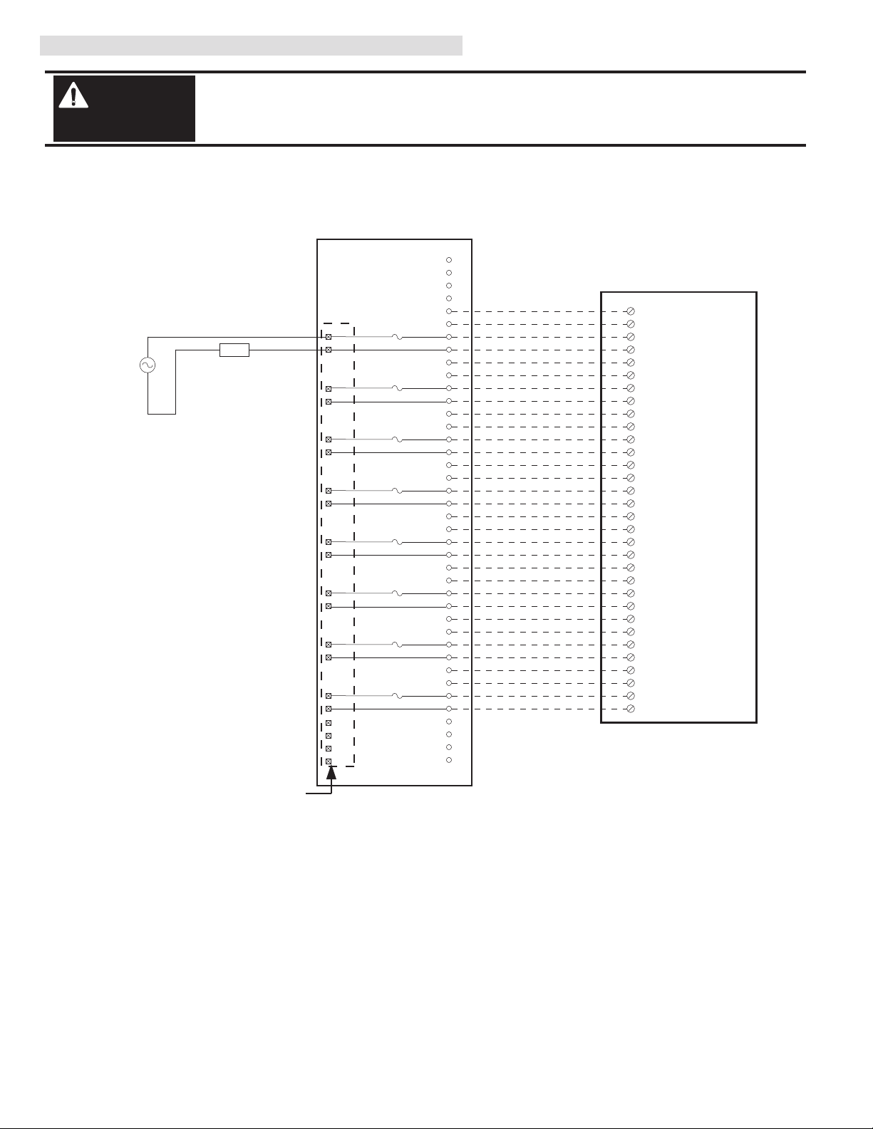
IV. Conversion Module Wiring Diagram (Continued)
Conversion Module Installation and Application Considerations
The maximum B840-108 relay module resistive current limits versus 1756-OX8I limits are as follows: (NOTE: for switching
and inductive current and voltage ratings, refer to the modules Installation Manual)
B840-108 1756-OX8I w/ 1492-CABLE003Y
a) Current/Point
3A Cont, 2A Switching 100VA 2A @ 30V DC/125V AC
The B840-108 is fused per output point. The 1756-OX8I is NOT fused. The 1492-CM800-LD015 provides a 5x20mm fuse
per 1756-OX8I point. Fuse rating for this configuration is 2 Amps.
The 1492-CABLE003Y current is limited to 2A per pin.
The B840-108 allowed using a circuit board jumper to configure each relay output for N.O. or N.C. operation (N.O. default),
but only one set of field terminals was provided on the module. The 1492-CM800-LD015 conversion module is set for N.O.
relay operation. If the N.C. contact of the 1756-OX8I relay module is required, it may be accessed by modifying the wiring at
the module’s swing-arm (terminal block).
Refer to your B840-108 and 1756-OXI Installation Manual wiring schematics and diagrams. Ensure 1756 output module
ratings are not exceeded. [Reference Doc: 41170-783 (Version 03)]
1756-OX8I
1492-CABLE003Y
1492-CM800-LD015
Conversion: B840-108 to 1756-OX8I with 1492-CM800-LD015
B840-108 Swing Arm
1
2
3
4
1
5
2
6
3
7
4
8
6
9
7
10
8
11
9
12
11
13
12
13
15
14
16
16
17
17
18
19
19
18
20
14
15
21
20
22
23
24
25
26
27
28
29
30
31
32
33
35
36
5
37
10
38
39
40
34
Output 1
Output 2
Output 3
Output 4
Output 5
Output 6
Output 7
Output 8
Not Used
Not Used
Output 1A
Output 2A
Output 3A
Output 4A
Output 5A
Output 6A
Output 7A
Output 8B
Output 1B
Output 2B
Output 3B
Output 4B
Output 5B
Output 6B
Output 7B
Output 8A
LOAD
L1
L2
Not Used
Not Used
OUT-0 N.C.
2
1
OUT-0 N.O.
4
3
OUT-1 N.C.
6
5
OUT-1 N.O.
8
7
OUT-2 N.C.
10
9
OUT-2 N.O.
12
11
OUT-3 N.C.
14
13
Orange
Blue
White/Black
Red/Black
Green/Black
Orange/Black
Blue/Black
Black/White
Red/White
Green/White
Blue/White
Black/Red
White/Red
Orange/Red
Blue/Red
Red/Green
OUT-3 N.O.
16
15
OUT-4 N.C.
18
17
OUT-4 N.O.
20
19
OUT-5 N.C.
22
21
OUT-5 N.O.
24
23
OUT-6 N.C.
26
25
OUT-6 N.O.
28
27
OUT-7 N.C.
30
29
Orange/Green
Black/White/Red
White/Black/Red
Red/Black/White
Green/Black/White
Orange/Black/White
Blue/Black/White
Black/Red/Green
White/Red/Green
Red/Black/Green
Green/Black/Orange
Orange/Black/Green
Blue/White/Orange
Black/White/Orange
White/Red/Orange
Orange/White/Blue
OUT-7 N.O.
32
31
L1-0
L1-0
L1-1
L1-1
L1-2
L1-2
L1-3
L1-3
L1-4
L1-4
L1-5
L1-5
L1-6
L1-6
L1-7
L1-7
There are several key application considerations and system specifications (bottom of drawing) when
using these components (conversion module, cable and output module). Read and understand these
considerations before installation. In addition, refer to the current draw requirements of the existing
loads for this configuration to ensure they are within the current ratings of the 1756 output module.
WARNING
Page 4

(4)
10000021918 (Version 01)
V. Fuse Installation and Replacement
The 1492-CM800-LD015 conversion module has eight (8) mechanical fuses located on the circuit board inside the
modules plastic case. The following explains how to install and replace the fuses.
1) Remove the screw from the bottom of the conversion module plastic case.
2) Push UP and IN on the locking tab at the other end of the conversion module case.
3) Remove the top cover (part which has the nameplate label) from the module case.
Locking Tab
IN
UP
Page 5

Fuse Holders and
Fuse Data
(5)
10000021918 (Version 01)
V. Fuse Installation and Replacement (Continued)
4) To add and/or replace the fuse turn the circuit board over. The fuses and fuse information is visible on the circuit
board.
NOTES:
1) For conversion module operation a fuse must be inserted into each of the 8 fuse holders.
2) Physical Fuse Size: 5 x 20 mm
3) Possible Fuse Suppliers: Shurter (Part Number:
0032.3123)
and Cooper Bussmann (Part Number:
GMC-2A)
.
4) Fuse Current Rating Based on Conversion System Components: 2 Amps
VI. Conversion Module Re-assembly After Fuse Insertion/Replacement
1) To re-assemble the fused module, place the circuit board into the label side half of the module case with the fused
side of the circuit board UP.
Case surface with module label
Page 6

(6)
10000021918 (Version 01)
VI. Conversion Module Re-assembly After Fuse Insertion/Replacement (Continued)
2) Take the module case half with the locking tab and partially insert the tab into the mating slot of the other half.
3) At the other end of the module case, ensure the bottom guide/retainer clears the top locking extension. Push the
2 case halves up and in until you here the locking tab snap into place.
4) Replace the module case screw [(maximum torque 0.7 Nm (6.9 lb-in)].
Locking Tab: Partially Inserted
Extension
Guide / retainer
Page 7

(7)
10000021918 (Version 01)
VII. 1492-CM800-LD015 Conversion Module Specifications
(Operating specifications are when installed in the Conversion System base / cover-plate assembly)
Specification Value
Dimensions 288.9 mm (height) x 139.7 mm (depth) x 44.5 mm (width)
11.37 in. (height) x 5.5 in. (depth) x 1.75 in. (width)
Approximate Shipping Weight 300g (0.66 lbs) (includes carton)
Storage Temperature -40 to +85°C (-40 to +185°F)
Operating Temperature 0 to 55°C (32 to 131°F)
Operating Humidity 5 to 95% at 55°C (non-condensing)
Shock
Non-operating
Operating
50g
30g
Operating Vibration 2g @ 10-500Hz
150 Vdc, 125 Vac @ 47 to 63 Hz
Maximum Operating Voltage
Max. Module Operating Current
Per Point:
Per Module:
2 Amps (1492-CABLE connection pins are limited to 2A per pin)
12 Amps
Agency Certifications
UL Classified: Under UL File Number E113724
CSA
CE: compliant for all applicable directives
Pollution Degree 2
Environmental Rating IP20
Refer to the Wiring Diagram(s) for
current limits for a specific configuration.
NOTICE
Fusing Eight, 2 Amps, 5 x 20 mm
Page 8

10000021918 (Version 01)
Printed in Germany
Article No. 4351990000
VIII. Appendix A - 800 Housing to 1756 Chassis Conversion System Selection Process
1) Determine the number of 800 I/O modules actually used in the 800 I/O Housing to be converted to 1756 I/O.
2) Review the data in Column 5 from the below table, and select a 1756 I/O Chassis which meets your conversion
needs from Step 1. Ensure the information from the I/O Conversion module table is reviewed first since in some
cases, two 1756 modules are needed to replace one 800 I/O module.
3) Once the 1756 Chassis is selected, refer to Column 7 and select the Conversion Assembly.
One chassis slot required for the ControlLogix processor or a remote I/O adapter type module.
The footprint and mounting dimensions of the 1492 Conversion Assembly (base plate and cover plate) match those of the
Modicon I/O Housing.
Width dimension includes the 1756 Chassis power supply.
Surplus Chassis width as compared to the 800 I/O Housing is divided equally when mounting it on the Conversion Assembly.
Mounting holes for the 1756 I/O Chassis are pre-drilled and pre-tapped into the Conversion Assembly cover plate.
Modicon is a Registered Trademark of Group Schneider
AS-H810-xxx
AS-H819-103
AS-H819-209
AS-H819-100
AS-H827-103
AS-H827-209
AS-B827-100
Modicon 800 I/O
Housing Cat Number
1492-MUA4-MB3
1492-MUA7-A10-
MB4679
1492-MUA10-A13-
MB81011
Conversion Assembly
Catalog Number
3
4
6
7
8
10
11
10.25”
17.5”
17.5”
17.5”
27.1”
27.1”
27.1”
10.25”
A7 = 14.49”
A10 = 19.02”
A7 = 14.49”
A10 = 19.02”
A7 = 14.49”
A10 = 19.02”
A10 = 19.02”
A13 = 23.15”
A10 = 19.02”
A13 = 23.15”
A10 = 19.02”
A13 = 23.15”
1756 Chassis
Width
Dimension
3
A7 = 6, A10=9
A7 = 6, A10=9
A7 = 6, A10=9
A10 = 9, A13=12
A10 = 9, A13=12
A10 = 9, A13=12
1756 I/O Chassis
Catalog Number
1 72 3 654
1756-A4
1756-A7
or
1756-A10
1756-A10
or
1756-A13
Max. Number
of 800 Housing
Slots for I/O
800 Housing
Width
Dimension
Max. Number
of 1756 Chassis
Slots for I/O
 Loading...