

Page 1
Field Wire Conversion Module for Modicon B877-111 to 1756-IF16
in Single-ended Current or Voltage Mode
(Cat 1492-CM800-LA002)
10000021831 (Version 00)
Printed in Germany
Local language (French, Italian, German & Spanish) versions of this document can be downloaded by going to www.ab.com.
In the left margin click on Publications Library and Literature Library. In the Search Area (right margin), Search by Catalog
Number and in the Search box type in the catalog number of the conversion system component.
I. Module Description
The 1492-CM800-LA002 conversion module provides field wire signal conversion from a Modicon® B877-111,
analog, 16-channel, single-ended current or voltage input module to a ControLogix 1756-IF16, analog, 16-channel,
single-ended current or voltage input module. The conversion module provides the mating connections to the B877111 swing-arm (terminal block) with the attached field wires. It routes those signals, via its 25-pin, D-shell connector
and a 1492-ACABLEUB or 1492-ACABLEUA pre-wired cable to the compatible terminals of the 1756-IF16 (refer
to the Wiring Diagrams on pages 2 and 3).
II. Module Installation
The 1492-CM800-LA002 conversion module must be installed in a 1492 conversion system base-plate and coverplate assembly. The installation of the module into the assembly is explained in the Installation Manual that ships with
the conversion assembly. For a list of compatible assemblies refer to Appendix A.
III. Conversion Module Compatibility Matrix
This is the cable length in meters and tenths of meters (e.g. 015 = 1.5 meters). Recommended cable
length is 003 (00.3 meters).
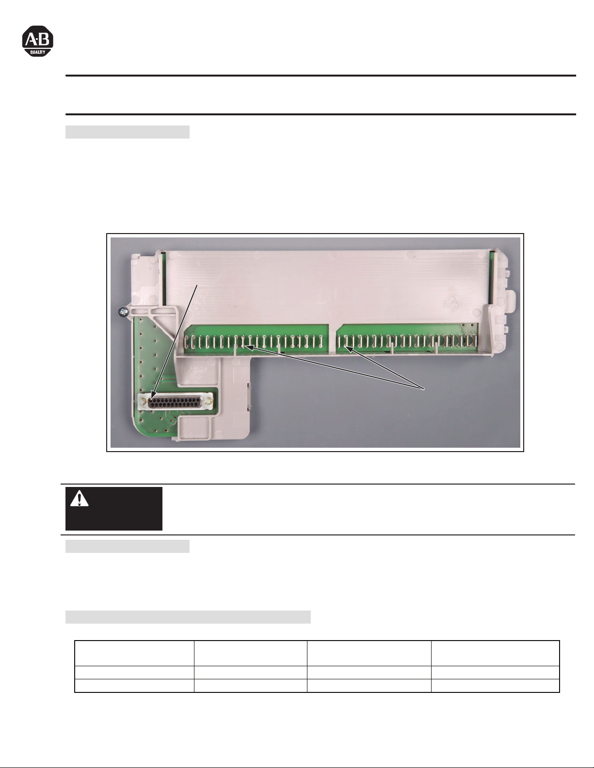
25pin D-shell connector for 1492-ACABLEUA or –ACABLEUB
Mating connector for
B800 Terminal Block
Conversion Module Compatible 800
Input Module
Compatible 1756
Input Module
Required 1492 Cable
1492-CM800-LA002 B877-111 (S-ended V) 1756-IF16 (S-ended V) 1492-ACABLEUA
1492-CM800-LA002 B877-111 (S-ended C) 1756-IF16 (S-ended C) 1492-ACABLEUB
1492-CM800-LA002 Conversion Module
De-energize and lockout any and all power to all I/O field devices connected to the Modicon 800 I/O
housing, and the power to the 800 I/O housing itself. Ensure all power is de-energized and locked out to
any device in the control cabinet where the conversion is to be performed. Ensure work is performed by
qualified personnel.
WARNING
Page 2
(2)
10000021831 (Version 00)
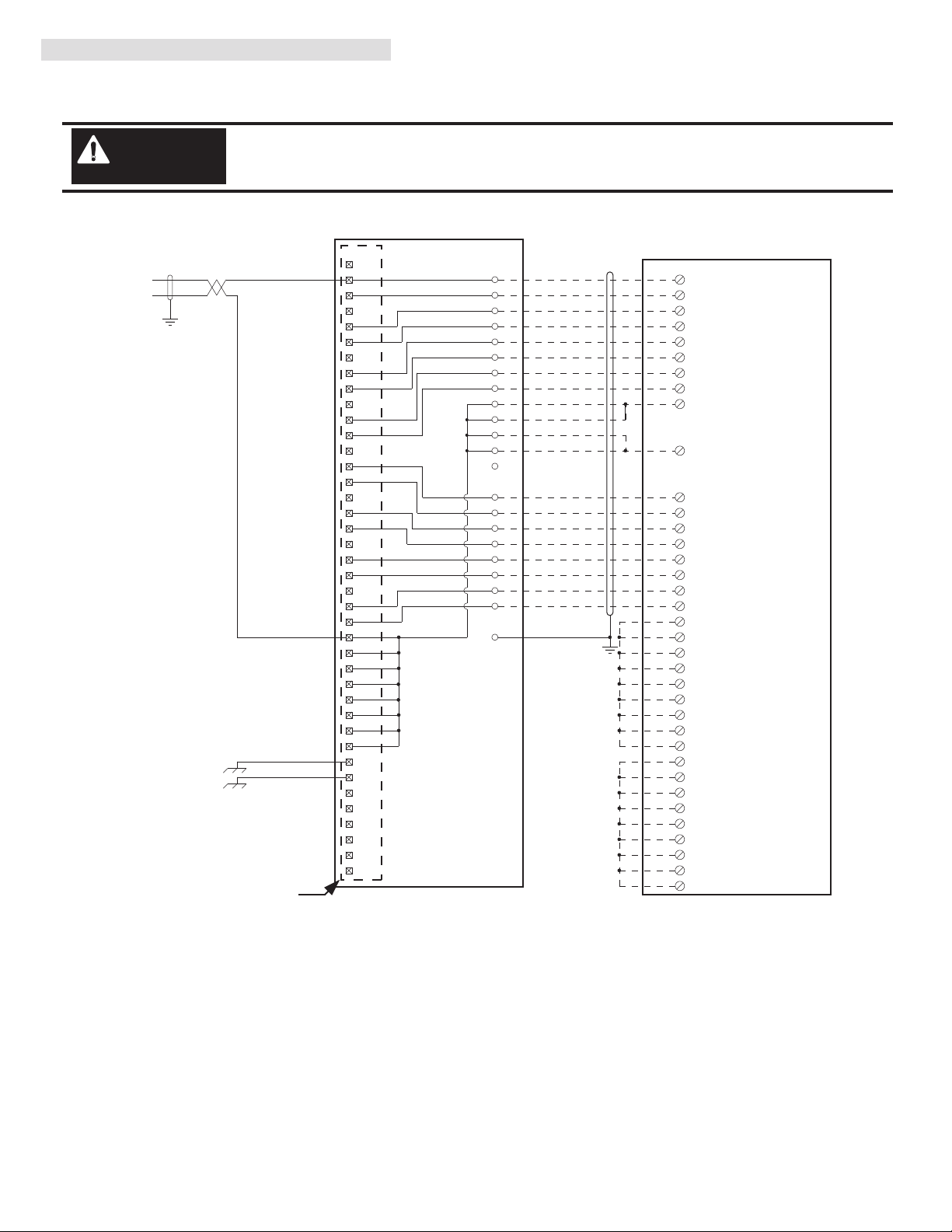
IV. Conversion Module Wiring Diagram
The following diagrams show the connections from the existing B877-111 swing-arm, through the conversion module, 1492
cable and to the 1756-IF16 analog input module. The diagrams can be used as an aid in possible system troubleshooting.
Conversion: B877-111 to 1756-IF16 (Single Ended Current) with 1492-CM800-LA002
Conversion Module Installation and Application Considerations
The B875-111 indicated differential inputs. When it was configured for single ended inputs, it was referred to as a B877-111.
SHIELD GROUNDING: For single ended current analog inputs both the B877-111 and 1756-IF16 recommend grounding the field wiring shield
at the analog source/device. As such, no shield ground modifications should be requried. The pre-wired cable used between the 1492-CM800LA002 and the 1756-IF16 [1492-ACABLE003UB] provides a shield ground lug to ground the shield at the 1756 ControlLogix chassis, this must be
connected.
The B877-111 recommended placing jumpers from UNUSED to USED analog input channels. These jumpers MUST be removed or they will
result in improper operation.
The B77-111 analog input ranges were configured by DIP switches on the module. The appropriate range for the 1756-IF16 is configured by
software.
This design assumes that all inputs on the B877-111 were connected to current transmitters. If there was a mix of current and voltage transmitters, then modification of pre-wired cable will need to occur at the 1756-IF16 terminal block. Refer to the 1756-IF16 Installation Manual for
modification details.
CASE GROUND: If connected, remove this wire from the B877-111 terminal block, as it serves no purpose for the 1756-IF16.
Refer to your B877-111 and 1756-IF16 Installation and User Manuals for additional information concerning comparisons of module wiring,
features, and configuration details. [Reference Doc: 41170-764 (Version 03)]
There are several key application considerations and system specifications (bottom of drawing) when
using these components (conversion module, cable and output module). Read and understand these
considerations before installation.
WARNING
3
7
8
11
12
15
16
5
9
13
17
25
29
Input 7
Input 8
Input 3
Input 5
Input 4
Input 6
3
2
1
14
15
16
17
18
4
6
8
10
19
12
13
25
24
23
22
20
21
+
-
4
Input 1
Input 2
2
6
10
14
23
27
28
31
32
35
36
Input 15
Input 16
Input 11
Input 13
Input 12
Input 14
24
Input 9
Input 10
22
26
30
34
SH
33
37
Input 1,2 Return
1
40
18
19
20
21
38
39Voltage Reference -
Voltage Reference +
Not Used
Not Used
Not Used
Not Used
Case Ground
Case Ground
2
IN-0
IN-1
4
IN-2
6
IN-3
8
IN-4
12
IN-5
14
IN-6
16
IN-7
18
RTN
10
RTN
27
RTN
28
IN-9
22
IN-8
20
IN-11
26
IN-10
24
IN-15
36
IN-14
34
Red
RTN
9
Brown
Black
White
White/Black
White/Brown
White/Red
White/Orange
Orange
Yellow
Green
Blue
IN-13
32
IN-12
30
Violet
Gray
White/Black/Brown
White/Gray
White/Violet
White/Blue
White/Yellow
White/Green
iRTN-1
3
iRTN-0
1
iRTN-3
7
iRTN-2
5
iRTN-7
17
iRTN-6
15
iRTN-5
13
iRTN-4
11
iRTN-9
21
iRTN-8
19
iRTN-11
25
iRTN-10
23
iRTN-15
35
iRTN-14
33
iRTN-13
31
iRTN-12
29
Not Used
Not Used
Not Used
Not Used
Not Used
Not Used
Not Used
Not Used
Input 3,4 Return
Input 5,6 Return
Input 7,8 Return
Input 9,10 Return
Input 15,16 Return
Input 13,14 Return
Input 11,12 Return
B877-111 Swing Arm
1756-IF16
1492-ACABLE003UB
1492-CM800-LA002
Page 3

(3)
10000021831 (Version 00)
IV. Conversion Module Wiring Diagram (Continued)
Conversion: B877-111 to 1756-IF16 (Single Ended Voltage) with 1492-CM800-LA002
Conversion Module Installation and Application Considerations
T1 The B875-111 indicated differential inputs. When it was configured for single ended inputs, it was referred to as a B877-111.
SHIELD GROUNDING: For single ended voltage analog inputs both the B877-111 and 1756-IF16 recommend grounding the field wiring shield at
the analog source/device. As such, no shield ground modifications should be requried. The pre-wired cable used between the 1492-CM800-LA002
and the 1756-IF16 [1492-ACABLE003UA] provides a shield ground lug to ground the shield at the 1756 ControlLogix chassis, this must be
connected.
The B877-111 recommended placing jumpers from UNUSED to USED analog input channels. These jumpers can be removed if desired. They
are not required on the 1756-IF16, but they will not impact its operation (in voltage mode) if they are left connected.
The B77-111 analog input ranges were configured by DIP switches on the module. The appropriate range for the 1756-IF16 is configured by
software.
This design assumes that all inputs on the B877-111 were connected to voltage transmitters. If there was a mix of current and voltage transmitters,
then modification of pre-wired cable will need to occur at the 1756-IF16 terminal block. Refer to the 1756-IF16 Installation Manual for modification
details.
CASE GROUND: If connected, remove this wire from the B877-111 terminal block, as it serves no purpose for the 1756-IF16.
Refer to your B877-111 and 1756-IF16 Installation and User Manuals for additional information concerning comparisons of module wiring,
features, and configuration details. [Reference Doc: 41170-785
(Version 03)]
There are several key application considerations and system specifications (bottom of drawing) when
using these components (conversion module, cable and output module). Read and understand these
considerations before installation.
WARNING
3
7
8
11
12
15
16
5
9
13
17
25
29
Input 7
Input 8
Input 3
Input 5
Input 4
Input 6
3
2
1
14
15
16
17
18
4
6
8
10
19
12
13
25
24
23
22
20
21
+
-
4
Input 1
Input 2
2
6
10
14
23
27
28
31
32
35
36
Input 15
Input 16
Input 11
Input 13
Input 12
Input 14
24
Input 9
Input 10
22
26
30
34
SH
33
37
Input 1,2 Return
1
40
18
19
20
21
38
39
Voltage Reference -
Voltage Reference +
Not Used
Not Used
Not Used
Not Used
Case Ground
Case Ground
Not Used
Not Used
Not Used
Not Used
Not Used
Not Used
Not Used
Not Used
Input 3,4 Return
Input 5,6 Return
Input 7,8 Return
Input 9,10 Return
Input 15,16 Return
Input 13,14 Return
Input 11,12 Return
2
IN-0
IN-1
4
IN-2
6
IN-3
8
IN-4
12
IN-5
14
IN-6
16
IN-7
18
RTN
10
RTN
27
RTN
28
IN-9
22
IN-8
20
IN-11
26
IN-10
24
IN-15
36
IN-14
34
Red
RTN
9
Brown
Black
White
White/Black
White/Brown
White/Red
White/Orange
Orange
Yellow
Green
Blue
IN-13
32
IN-12
30
Violet
Gray
White/Black/Brown
White/Gray
White/Violet
White/Blue
White/Yellow
White/Green
B877-111 Swing Arm
1756-IF16
1492-CM800-LA002
1492-ACABLE003UA
Page 4

10000021831 (Version 00)
Printed in Germany
V. 1492-CM800-LA002 Conversion Module Specifications
(Operating specifications are when installed in the Conversion System base / cover-plate assembly)
VI. Appendix A - 800 Housing to 1756 Chassis Conversion System Selection Process
1) Determine the number of 800 I/O modules actually used in the 800 I/O Housing to be converted to 1756.
2) Review the data in Column 5 from the below table, and select a 1756 I/O Chassis which meets your conversion
needs from Step 1. Ensure the information from the I/O Conversion module table is reviewed first since in some
cases, two 1756 modules are needed to replace one 800 I/O module.
3) Once the 1756 Chassis is selected, refer to Column 7 and select the Conversion Assembly.
One chassis slot required for the ControlLogix processor or a remote I/O adapter type module.
The footprint and mounting dimensions of the 1492 Conversion Assembly (base plate and cover plate) match those of the
Modicon I/O Housing.
Width dimension includes the 1756 Chassis power supply.
Surplus Chassis width as compared to the 800 I/O Housing is divided equally when mounting it on the Conversion Assembly.
Mounting holes for the 1756 I/O Chassis are pre-drilled and pre-tapped into the Conversion Assembly cover-plate.
Modicon is a Registered Trademark of Group Schneider.
Specification Value
Dimensions 288.9 mm (height) x 139.7 mm (depth) x 44.5 mm (width)
11.37 in. (height) x 5.5 in. (depth) x 1.75 in. (width)
Approximate Shipping Weight 300g (0.66 lbs) (includes carton)
Storage Temperature -40 to +85°C (-40 to +185°F)
Operating Temperature 0 to 55°C (32 to 131°F)
Operating Humidity 5 to 95% at 55°C (non-condensing)
Shock
Non-operating
Operating
50g
30g
Operating Vibration 2g @ 10-500Hz
Maximum Operating Voltage 60 Vdc
Max. Module Operating Current
Per Point:
Per Module:
2 Amps (1492-CABLE connection pins are limited to 2A per pin)
12 Amps
Agency Certifications
UL Classified: Under UL File Number E113724
CSA
CE: compliant for all applicable directives
Pollution Degree 2
Environmental Rating IP20
AS-H810-xxx
AS-H819-103
AS-H819-209
AS-H819-100
AS-H827-103
AS-H827-209
AS-B827-100
Modicon 800 I/O
Housing Cat Number
1492-MUA4-MB3
1492-MUA7-A10-
MB4679
1492-MUA10-A13-
MB81011
Conversion Assembly
Catalog Number
3
4
6
7
8
10
11
10.25”
17.5”
17.5”
17.5”
27.1”
27.1”
27.1”
10.25”
A7 = 14.49”
A10 = 19.02”
A7 = 14.49”
A10 = 19.02”
A7 = 14.49”
A10 = 19.02”
A10 = 19.02”
A13 = 23.15”
A10 = 19.02”
A13 = 23.15”
A10 = 19.02”
A13 = 23.15”
1756 Chassis
Width
Dimension
3
A7 = 6, A10=9
A7 = 6, A10=9
A7 = 6, A10=9
A10 = 9, A13=12
A10 = 9, A13=12
A10 = 9, A13=12
1756 I/O Chassis
Catalog Number
1 72 3 654
1756-A4
1756-A7
or
1756-A10
1756-A10
or
1756-A13
Max. Number
of 800 Housing
Slots for I/O
800 Housing
Width
Dimension
Max. Number
of 1756 Chassis
Slots for I/O
Refer to the Wiring Diagram(s) for
current limits for a specific configuration.
NOTICE
Article No. 4351810000
 Loading...