

Page 1
Digital I/O Conversion Module
(Cat 1492-CM1771-LD013)
I. Description
This Digital I/O Conversion Module provides for the conversion of (1) 1771, 32 point I/O modules to be converted
to (2) 1756, 16 point I/O module and consists of the following:
(1) 1771 Module (32pt) to (2) 1756 Modules (16pt)
(1) Conversion Module: 1492-CM1771-LD013
(1) Cable: 1492-CONCAB005S3 or 1492- CONCAB005S4 (Table 2)
(1) Conversion Mounting Assembly: 1492-MUA… (Table 1)
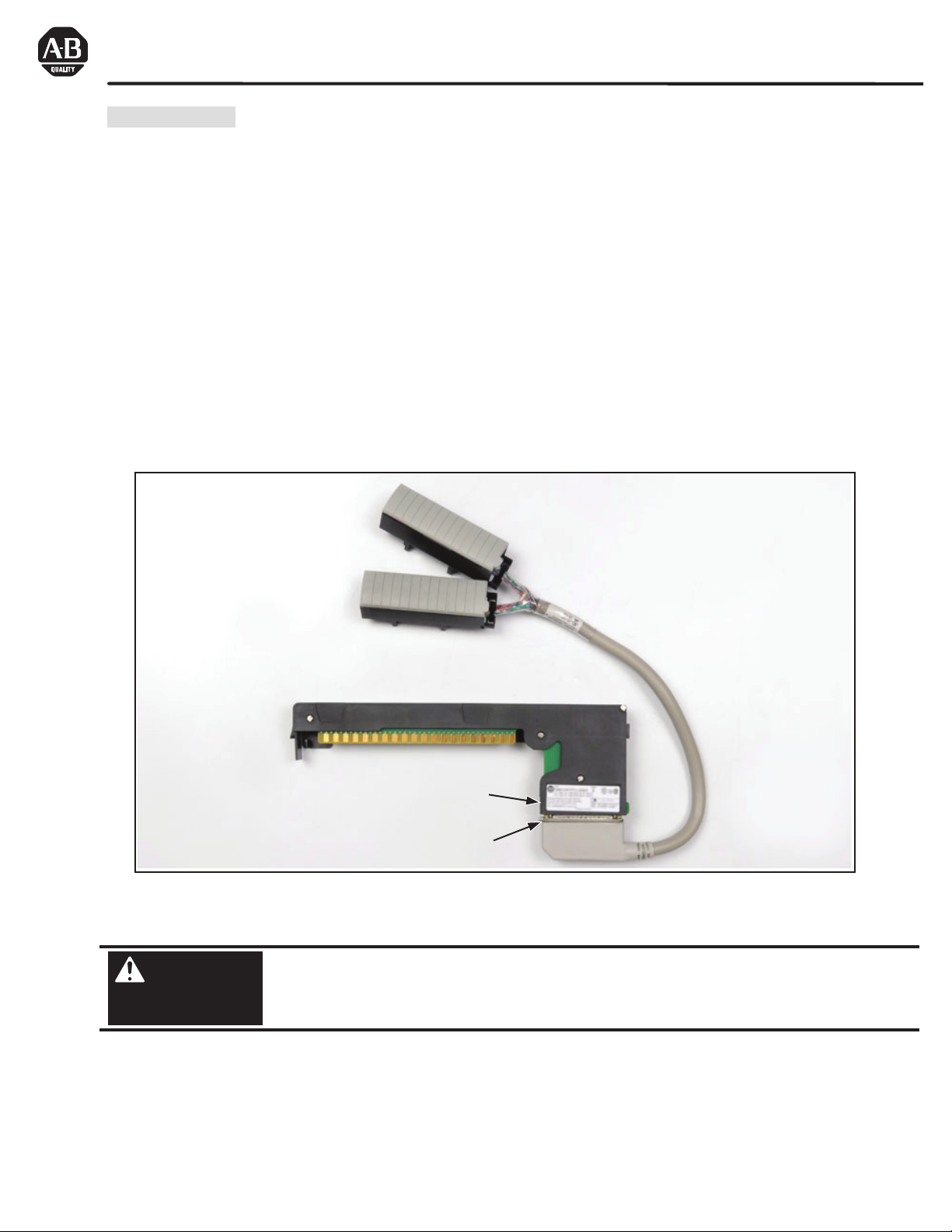
This conversion is accomplished without the removal of any field wires from the existing 1771 Swing Arm. The
existing 1771 Swing Arm fits directly onto the edge connector of the 1492 Conversion Module. On one end of
the 1492 Cable is (1) connector for the Conversion Module. On the other end are (2) Removable Terminal
Blocks (RTBs) for the (2) 1756 I/O modules, as shown in the photo below. The I/O signals are routed through
the 1492 Conversion Module and the 1492 Cable to the appropriate terminals on the (2) 1756 I/O modules per
the Wiring Diagrams in Section V. As standard, the 1492 Cables are 0.5M long, but we also offer a 1.0M cable
length. Refer to the footnotes in Table 2 for further details.
WARNING
Cable
1492-CONCAB005
Conversion Compatibility
and Product I.D. Label
37-Pin Connector for cable
1492-CONCAB005
1492-CM1771-LD013 Conversion Module
De-energize and lockout any and all power to all I/O field devices connected to the A-B 1771 I/O
chassis, and the power to the 1771 I/O chassis itself. Ensure all power is de-energized and locked out to
any device in the control cabinet where the conversion is to be performed. Ensure work is performed by
qualified personnel.
S_
S_
PN-114285
DIR 10000060096 (Version 01)
Publication 1492-IN044B-EN-E
Printed in U.S.A.
Page 2
II. Installation
:
The 1492 Conversion Modules must be installed in a 1492 Conversion Mounting Assembly (see Table 1 below). A
complete System Installation Manual ships with the 1492 Conversion Mounting Assembly.
1) Determine the quantity of each type of 1771 I/O modules used in the 1771 I/O Chassis to be converted.
2) Select the applicable 1492 Conversion Modules from Table 2, Section III.
3) Review the Max Slots for I/O and Chassis Width data from the Table 1 below.
4) Select a 1756 I/O Chassis which has enough I/O Slots.
NOTE: (2) I/O slots are required in the 1756 Chassis for conversions where (1) 1771 I/O module converts to (2) 1756 I/O
modules.
5) Select the 1492 Conversion Mounting Assembly which has enough Conversion Module slots.
NOTE: (2) Conversion Module slots are required in the 1492 Conversion Mounting Assembly for conversions where (2)
1771 I/O module convert to (1) 1756 I/O modules.
NOTE: The 1492 Conversion Mounting Assembly has the same Height & Width foot-print as the 1771 Chassis and is
designed to use the same mounting hardware. The combined Depth of the 1492 Conversion Mounting Assembly with the
1756 Chassis mounted on top is 10.25 inches (Controller w/key) or 10.0 inches (Controller w/o key). Dimension drawings
are included in the System Installation Manual that ships with the 1492 Conversion Mounting Assembly.
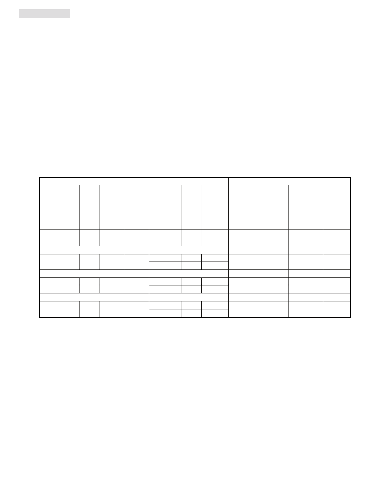
Table 1: Bulletin 1771 to 1756 Chassis Conversion
1771 Chassis 1756 Chassis Conversion Mounting Assembly
Max
Cat. No.
1771-A1B 4 9.01 12.61
1771-A2B 8 14.01 17.61
1771-A3B1
1771-A4B 16 24.01
Slots
I/O
Chassis Width
without
for
Power
Supply
12 19.01
with
Power
Supply
Cat. No.
1756-A4
1756-A7
1756-A7
1756-A10
1756-A10
1756-A13
1756-A13
1756-A17
Max
Slots
Chassis
for
I/O
12 23.15
12 23.15
16 29.06
Width
3 10.35
6 14.49
6 14.49
9 19.02
9 19.02
Max Slots
Cat. No.
1492-MUA1B-A4-A7 4 9.01
1492-MUA2B-A7-A10 8 14.01
1492-MUA3-A10-A13 12 19.01
1492-MUA4-A13-A17 16 24.01
for
Conversion
Modules
Chassis
Width
oot Notes
1771-A3B is not listed as it is used for 19 inch wide instrumentation panels.
Notice that the 1756 Chassis Width sometimes exceeds the 1771 Chassis Width, with or without the Power Supply. The
Cover-Plate of the 1492 Conversion Mounting Assembly allows the 1756 Chassis to be Left justified, Right justified or
Centered. A complete System Installation Manual ships with the 1492 Conversion Mounting Assembly.
PN-114285
DIR 10000060096 (Version 01)
Publication 1492-IN044B-EN-E
(2)
Page 3
III. Compatibility
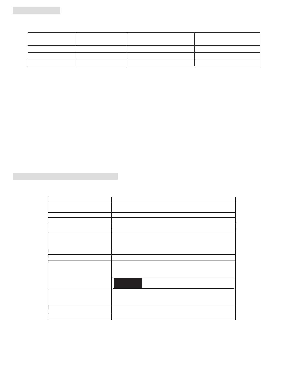
Table 2: Bulletin 1771 to 1756 Conversion Modules and Cables
1771
Digital I/O Module
Digital I/O Module
1756
1492
Conversion Module
1492
Cable
1771-OAN 1756-OA16 (Qty 2) 1492-CM1771-LD013 1492-CONCAB005S3
1771-OVN 1756-OV16E (Qty 2) 1492-CM1771-LD013 1492-CONCAB005S3
1771-OWNA 1756-OW16I (Qty 2) 1492-CM1771-LD013 1492-CONCAB005S4
Foot Notes:
To understand any issues concerning I/O module compatibility, refer to the Installation Manuals for the specific 1771
and 1756 I/O modules involved. The (2) 1756 modules must be located directly next to each other in the 1756
chassis.
The 3 numbers indicate the cable length of the 1492 Cable. Recommended cable length of 0.5M is shown.
Alternative cable lengths are as follows:
1.0M = 1492-CONCAB010S3
1.0M = 1492-CONCAB010S4
IV. Conversion Module Specifications
(Operating specifications are when installedin the Conversion System base / cover-plate assembly)
Specification
Dimensions
Approximate Shipping Weight
Storage Temperature
Operating Temperature
Operating Humidity
Shock
Non-operating
Operating
Operating Vibration
Maximum Operating Voltage
Max. Module Operating Current
Per Point:
Per Module:
Agency Certifications
Pollution Degree
Environmental Rating IP20
Value
11.81 in. (height) x 4.38 in. (depth) x 1.5 in. (width)
300 mm. (height) x 111.25 mm (depth) x 38.1 mm (width)
265.4 g (0.58 lbs) (includes carton)
-40 to +85°C (-40 to +185°F)
0 to 60°C (32 to 140°F)
5 to 95% at 60°C (non-condensing)
50g
30g
2g at 10 to 500Hz (Agrees with 1756 I/O module specifications)
240 Vac at 47 to 63Hz
2 Amps
4 Amps
UL Classified: Under UL File Number E113724
CSA
CE: compliant for all applicable directives
2
NOTICE
Refer to the Wiring Diagram(s) for
current limits for a specific configuration.
PN-114285
DIR 10000060096 (Version 01)
Publication 1492-IN044B-EN-E
(3)
Page 4
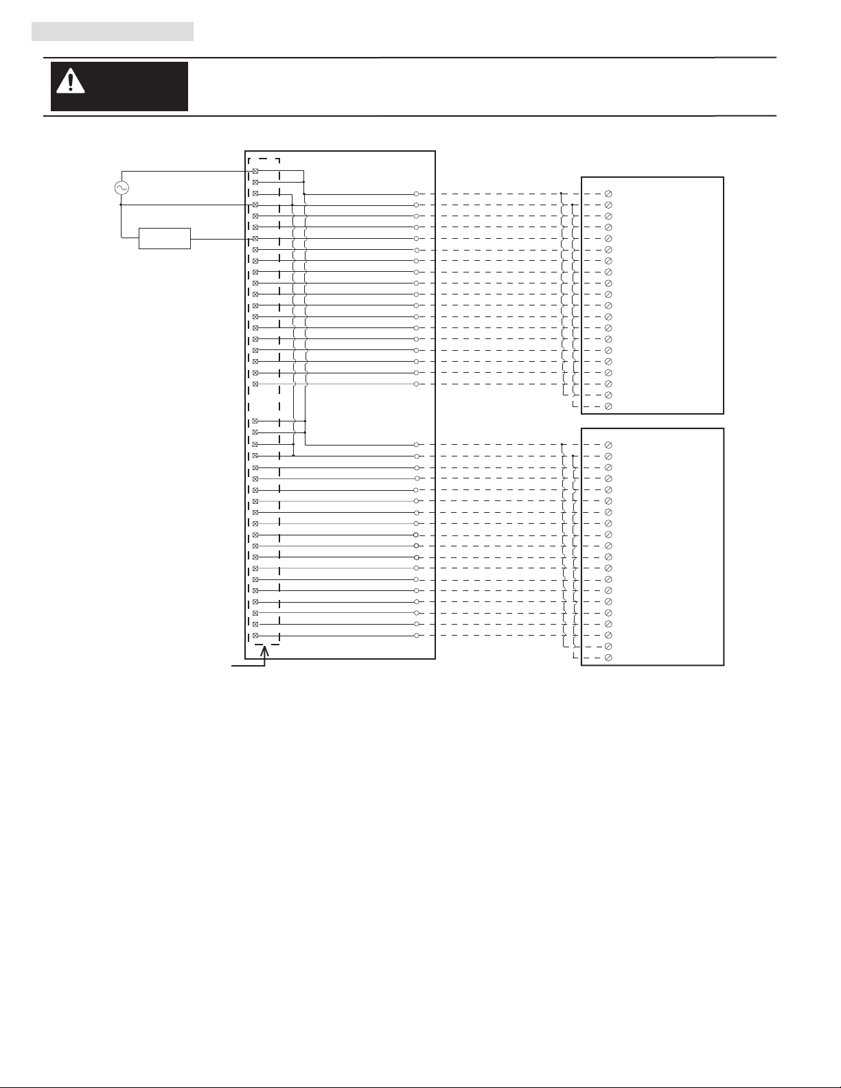
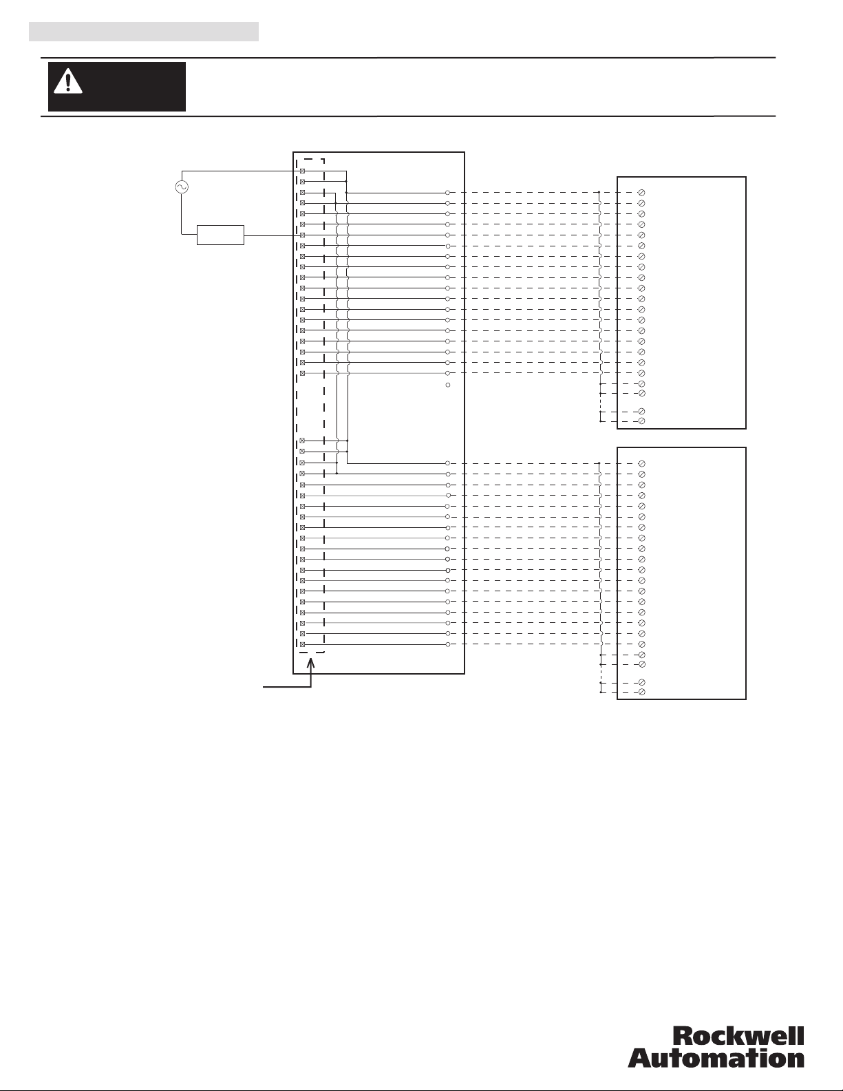
V. Wiring Diagrams
Conversion: 1771-OAN (1) to 1756-OA16 (2)
WARNING
L1
L2
Output
Device
1771-WN Swing Arm
From 1771-OAN
There are several key application considerations and system specifications (bottom of drawing) when
using these components (conversion module, cable and input module). Read and understand these
considerations before installation.
Conversion Module
Output 00
Output 01
Output 02
Output 03
Output 04
Output 05
Output 06
Output 07
Output 10
Output 11
Output 12
Output 13
Output 14
Output 15
Output 16
Output 17
L1
L1
L2
L2
Output 00
Output 01
Output 02
Output 03
Output 04
Output 05
Output 06
Output 07
Output 10
Output 11
Output 12
Output 13
Output 14
Output 15
Output 16
Output 17
L2
L2
L1
L1
1492-CM1771-LD013
1
11
10
20
2
3
4
5
6
7
8
9
12
13
14
15
16
17
18
19
21
31
30
40
22
23
24
25
26
27
28
29
32
33
34
35
36
37
38
39
1492-CONCAB005S3
1
Black
2
White
Red
3
Green
4
Orange
5
6
Blue
7
White/Black
8
Red/Black
9
Green/Black
10
Orange/Black
11
Blue/Black
12
Black/White
13
Red/White
14
Green/White
15
Blue/White
16
Black/Red
17
White/Red
Orange/Red
18
Blue/Red
19
Red/Green
20
Orange/Green
21
Black/White/Red
22
White/Black/Red
23
Red/Black/White
24
Green/Black/White
25
Orange/Black/White
26
27
Blue/Black/White
28
Black/Red/Green
White/Red/Green
29
Red/Black/Green
30
Green/Black/Orange
31
Orange/Black/Green
32
Blue/White/Orange
33
Black/White/Orange
34
White/Red/Orange
35
Orange/White/Blue
36
White/Red/Blue
37
Cable
10
9
1
2
3
4
5
6
7
8
11
12
13
14
15
16
17
18
20
19
10
9
1
2
3
4
5
6
7
8
11
12
13
14
15
16
17
18
20
19
1756-OA16
L1-0
L2-0
OUT-0
OUT-1
OUT-2
OUT-3
OUT-4
OUT-5
OUT-6
OUT-7
OUT-8
OUT-9
OUT-10
OUT-11
OUT-12
OUT-13
OUT-14
OUT-15
L1-1
L2-1
1756-OA16
L1-0
L2-0
OUT-0
OUT-1
OUT-2
OUT-3
OUT-4
OUT-5
OUT-6
OUT-7
OUT-8
OUT-9
OUT-10
OUT-11
OUT-12
OUT-13
OUT-14
OUT-15
L1-1
L2-1
A ELUDOM
B ELUDOM
Conversion Module Installation and Application Considerations
This Bul. 1492 cable consists of a cable wired to two 1756-OA16 RTB. Recommended cable lengths of 0.5M or 1.0M (005=0.5M,
010=1.0M). See table 2 for other lengths.
The 1771-OAN module output current limits versus 1756-OA16 limits are as follows:
1771-OAN 1756-OA16 w/ 1492-CONCAB005S3
a) Current/Point 1A 0.5A
b) Current/Module 8A (32 pts) 2A (16 pts)
c) Surge Current/Point 10A for 25ms 5A for 43ms
The 1771-OAN has 4 groups (allowing 4 separate power supplies). This module/cable combination ties all 4 groups from the 1771-OAN
together. Field wiring modification must be made to accommodate this if mulitple supplies were used. If more than 1 supply was used, all but
1 of the power supplies must be removed.
The 1771-OAN did not allow connections for L2, however the 1756-OA16 requires an L2 connection for proper operation. The 1771-OAN
did not use terminals 10, 20, 30, 40. These terminals have been reassigned for an L2 connection in this application. The installer must
rewire L2 to one of these terminals.
Refer to your 1771-OAN and 1756-OA16 Installation Manual wiring schematics and diagrams for more details. Ensure 1756 output
module ratings are not exceeded.
This configuration uses two (2) 1756-OA16 output modules to replace a single 1771-OAN output module. This may require the use of a
larger 1756 I/O chassis and conversion mounting assembly. Ensure there is sufficient panel space to allow for this possibility.
[Reference Doc: 41170-942 (Version 02)]
PN-114285
DIR 10000060096 (Version 01)
Publication 1492-IN044B-EN-E
(4)
Page 5

V. Wiring Diagrams (Cont’d)
Conversion: 1771-OVN (1) to 1756-OV16E (2)
WARNING
L1
L2
1771-WN Swing Arm
From 1771-OVN
There are several key application considerations and system specifications (bottom of drawing) when
using these components (conversion module, cable and input module). Read and understand these
considerations before installation.
Conversion Module
Output
Device
Output 00
Output 01
Output 02
Output 03
Output 04
Output 05
Output 06
Output 07
Output 10
Output 11
Output 12
Output 13
Output 14
Output 15
Output 16
Output 17
Output 00
Output 01
Output 02
Output 03
Output 04
Output 05
Output 06
Output 07
Output 10
Output 11
Output 12
Output 13
Output 14
Output 15
Output 16
Output 17
1492-CM1771-LD013
1
L1
11
L1
L2
10
L2
20
2
3
4
5
6
7
8
9
12
13
14
15
16
17
18
19
L1
21
31
L1
L2
30
40
L2
22
23
24
25
26
27
28
29
32
33
34
35
36
37
38
39
1492-CONCAB005S3
1
Black
2
White
Red
3
Green
4
Orange
5
6
Blue
7
White/Black
8
Red/Black
9
Green/Black
10
Orange/Black
11
Blue/Black
12
Black/White
13
Red/White
14
Green/White
15
Blue/White
16
Black/Red
17
White/Red
Orange/Red
18
Blue/Red
19
Red/Green
20
Orange/Green
21
Black/White/Red
22
White/Black/Red
23
Red/Black/White
24
Green/Black/White
25
Orange/Black/White
26
27
Blue/Black/White
28
Black/Red/Green
White/Red/Green
29
Red/Black/Green
30
Green/Black/Orange
31
Orange/Black/Green
32
Blue/White/Orange
33
Black/White/Orange
34
White/Red/Orange
35
Orange/White/Blue
36
White/Red/Blue
37
Cable
1756-OV16E
10
L1-0
9
L2-0
1
OUT-0
2
OUT-1
3
OUT-2
4
OUT-3
5
OUT-4
6
OUT-5
7
OUT-6
8
OUT-7
11
OUT-8
12
OUT-9
13
OUT-10
14
OUT-11
15
OUT-12
16
OUT-13
17
OUT-14
18
OUT-15
20
L1-1
19
L2-1
1756-OV16E
10
L1-0
9
L2-0
1
OUT-0
2
OUT-1
3
OUT-2
4
OUT-3
5
OUT-4
6
OUT-5
7
OUT-6
8
OUT-7
11
OUT-8
12
OUT-9
13
OUT-10
14
OUT-11
15
OUT-12
16
OUT-13
17
OUT-14
18
OUT-15
20
L1-1
19
L2-1
A ELUDOM
B ELUDOM
Conversion Module Installation and Application Considerations
This Bul. 1492 cable consists of a cable wired to two 1756-OV16E RTB. Recommended cable lengths of 0.5M or 1.0M (005=0.5M,
010=1.0M). See table 2 for other lengths.
The 1771-OVN module output current limits versus 1756-OV16E limits are as follows:
1771-OVN 1756-OV16E w/ 1492-CONCAB005S3
a) Current/Point 0.5A 1A
b) Current/Module 8A (32 pts) 8A (16 pts)
c) Surge Current/Point 2A for 10ms 2A for 10ms
The 1771-OVN has 4 groups (allowing 4 separate power supplies). This module/cable combination ties all 4 groups from the
1771-OVN together. Field wiring modification must be made to accommodate this if mulitple supplies were used. If more than 1 supply
was used, all but 1 of the power supplies must be removed.
The 1771-OVN did not allow connections for L2, however the 1756-OV16E requires an L2 connection for proper operation. The 1771-
OVN did not use terminals 10, 20, 30, 40. These terminals have been reassigned for an L2 connection in this application. The installer must
rewire L2 to one of these terminals.
Refer to your 1771-OVN and 1756-OV16E Installation Manual wiring schematics and diagrams for more details. Ensure 1756 output
module ratings are not exceeded.
This configuration uses two (2) 1756-OV16E output modules to replace a single 1771-OVN output module. This may require the use of a
larger 1756 I/O chassis and conversion mounting assembly. Ensure there is sufficient panel space to allow for this possibility.
[Reference Doc: 41171-018 (Version 00)]
PN-114285
DIR 10000060096 (Version 01)
Publication 1492-IN044B-EN-E
(5)
Page 6
V. Wiring Diagrams (Cont’d)
Conversion: 1771-OWNA (1) to 1756-OW16I (2)
WARNING
There are several key application considerations and system specifications (bottom of drawing) when
using these components (conversion module, cable and input module). Read and understand these
considerations before installation.
Conversion Module
L1
L2
Output
Device
Output 00
Output 01
Output 02
Output 03
Output 04
Output 05
Output 06
Output 07
Output 10
Output 11
Output 12
Output 13
Output 14
Output 15
Output 16
Output 17
Output 00
Output 01
Output 02
Output 03
Output 04
Output 05
Output 06
Output 07
Output 10
Output 11
Output 12
Output 13
Output 14
Output 15
Output 16
Output 17
1771-WN Swing Arm
From 1771-OWNA
1492-CM1771-LD013
1
L1
11
L1
L2
10
L2
20
2
3
4
5
6
7
8
9
12
13
14
15
16
17
18
19
L1
21
31
L1
L2
30
40
L2
22
23
24
25
26
27
28
29
32
33
34
35
36
37
38
39
1492-CONCAB005S4
1
Black
2
White
Red
3
Green
4
Orange
5
6
Blue
7
White/Black
8
Red/Black
9
Green/Black
10
Orange/Black
11
Blue/Black
12
Black/White
13
Red/White
14
Green/White
15
Blue/White
16
Black/Red
17
White/Red
Orange/Red
18
Blue/Red
19
Red/Green
20
Orange/Green
21
Black/White/Red
22
White/Black/Red
23
Red/Black/White
24
Green/Black/White
25
Orange/Black/White
26
27
Blue/Black/White
28
Black/Red/Green
White/Red/Green
29
Red/Black/Green
30
Green/Black/Orange
31
Orange/Black/Green
32
Blue/White/Orange
33
Black/White/Orange
34
White/Red/Orange
35
Orange/White/Blue
36
White/Red/Blue
37
Cable
1756-OW16I
2
L1-0
L2-0
1
OUT-0
3
OUT-1
5
OUT-2
7
OUT-3
9
OUT-4
11
OUT-5
13
OUT-6
15
OUT-7
17
OUT-8
19
OUT-9
21
OUT-10
23
OUT-11
25
OUT-12
27
OUT-13
29
OUT-14
31
OUT-15
4
L1-1
6
L1-1
32
L1-1
34
L1-1
1756-OW16I
2
L1-0
L2-0
1
OUT-0
3
OUT-1
5
OUT-2
7
OUT-3
9
OUT-4
11
OUT-5
13
OUT-6
15
OUT-7
17
OUT-8
19
OUT-9
21
OUT-10
23
OUT-11
25
OUT-12
27
OUT-13
29
OUT-14
31
OUT-15
4
L1-1
6
L1-1
32
L1-1
34
L1-1
A
B ELUDOMELUDOM
Conversion Module Installation and Application Considerations
This Bul. 1492 cable consists of a cable wired to two 1756-OW16I RTB. Recommended cable lengths of 0.5M or 1.0M (005=0.5M, 010=1.0M).
See table 2 for other lengths.
The 1771-OWNA module output current limits versus 1756-OW16I limits are as follows:
1771-OWNA 1756-OW16I w/ 1492-CONCAB005S4
a) Current/Point 1A 0.5A
b) Current/Module 12A (32 pts) 2A (16 pts)
The 1771-OWNA has 4 groups (allowing 4 separate power supplies). This module/cable combination ties all 4 groups from the 1771-OWNA
together. Field wiring modification must be made to accommodate this if mulitple supplies were used. If more than 1 supply was used, all but
1 of the power supplies must be removed.
The 1771-OWNA did not allow connections for L2, however the 1756-OW16I requires an L2 connection for proper operation. The 1771-OWNA
did not use terminals 10, 20, 30, 40. These terminals have been reassigned for an L2 connection in this application. The installer must rewire L2 to
one of these terminals.
Refer to your 1771-OWNA and 1756-OW16I Installation Manual wiring schematics and diagrams for more details. Ensure 1756 output module
ratings are not exceeded.
This configuration uses two (2) 1756-OW16I output modules to replace a single 1771-OWNA output module. This may require the use of a
larger 1756 I/O chassis and conversion mounting assembly. Ensure there is sufficient panel space to allow for this possibility.
1756-OW16I output modules has all inputs jumpered together pins 2 through 34 even.
[Reference Doc: 41171-019 (Version 00)]
PN-114285
DIR 10000060096 (Version 01)
Publication 1492-IN044B-EN-E
Printed in U.S.A.
 Loading...