

Page 1
Digital I/O Conversion Module
(Cat 1492-CM1771-LD012)
I. Description
This Digital I/O Conversion system provides for the conversion of (1) 1771, 8 point I/O module to (1) 1756, 8 point I/O module
OR (2) 1771, 8 point I/O modules to (1) 1756, 16 point I/O module and consists of the following:
(1) 1771 Module (8pt) to (1) 1756 Module (8pt)
(1) Conversion Modules: 1492-CM1771-LD012
(1) Cable: 1492-CONCAB005Y (Table 2)
(1) Conversion Mounting Assembly: 1492-MUA… (Table 1)
(2) 1771 Module (8pt) to (1) 1756 Module (16pt)
(2) Conversion Modules: 1492-CM1771-LD012
(1) Cable: 1492-C005C005X_ (Table 2)
(1) Conversion Mounting Assembly: 1492-MUA… (Table 1)
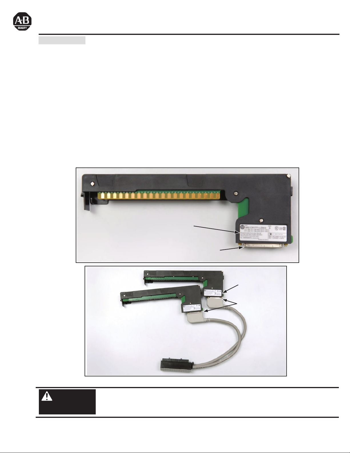
This conversion is accomplished without the removal of any field wires from the existing 1771 Swing Arms. The existing 1771
Swing Arms fit directly onto the edge connectors of the 1492 Conversion Modules. On one end of the 1492 Cables are (1)
or (2) connectors for the Conversion Modules. On the other end is the Removable Terminal Block (RTB) for the 1756 I/O
module, as shown in the photo below. The I/O signals are routed through the 1492 Conversion Module and the 1492 Cable
to the appropriate terminals on the 1756 I/O module per the Wiring Diagrams in Section IV. As standard, the 1492 Cables
are 0.5M long, but we also offer a 1.0M cable length. Refer to the footnotes in Table 2, Section III for further details.
Conversion Compatibility and
Product I.D. Label
37-Pin Connector for cable
1492-CM1771-LD012 Conversion Module
1492-CONCAB005Y
Conversion
Compatibility and
Product I.D. Label
25-Pin Connector
for cable
1492-C005005X_
WARNING
PN-114284
DIR 10000060095 (Version 01)
Publication 1492-IN042B-EN-E
Printed in U.S.A.
De-energize and lockout any and all power to all I/O field devices connected to the A-B 1771 I/O chassis,
and the power to the 1771 I/O chassis itself. Ensure all power is de-energized and locked out to any
device in the control cabinet where the conversion is to be performed. Ensure work is performed by
qualified personnel.
Page 2
II. Installation
:
The 1492 Conversion Modules must be installed in a 1492 Conversion Mounting Assembly (see Table 1 below). A
complete System Installation Manual ships with the 1492 Conversion Mounting Assembly.
1) Determine the quantity of each type of 1771 I/O modules used in the 1771 I/O Chassis to be converted.
2) Select the applicable 1492 Conversion Modules from Table 2, Section III.
3) Review the Max Slots for I/O and Chassis Width data from the Table 1 below.
4) Select a 1756 I/O Chassis which has enough I/O Slots.
NOTE: (2) I/O slots are required in the 1756 Chassis for conversions where (1) 1771 I/O module converts to (2) 1756 I/O
modules.
5) Select the 1492 Conversion Mounting Assembly which has enough Conversion Module slots.
NOTE: (2) Conversion Module slots are required in the 1492 Conversion Mounting Assembly for conversions where (2)
1771 I/O module convert to (1) 1756 I/O modules.
NOTE: The 1492 Conversion Mounting Assembly has the same Height & Width foot-print as the 1771 Chassis and is
designed to use the same mounting hardware. The combined Depth of the 1492 Conversion Mounting Assembly with the
1756 Chassis mounted on top is 10.25 inches (Controller w/key) or 10.0 inches (Controller w/o key). Dimension drawings
are included in the System Installation Manual that ships with the 1492 Conversion Mounting Assembly.
Table 1: Bulletin 1771 to 1756 Chassis Conversion
1771 Chassis 1756 Chassis Conversion Mounting Assembly
Max
Cat. No.
1771-A1B 4 9.01 12.61
1771-A2B 8 14.01 17.61
1771-A3B1
1771-A4B 16 24.01
Slots
I/O
Chassis Width
without
for
Power
Supply
12 19.01
with
Power
Supply
Cat. No.
1756-A4
1756-A7
1756-A7
1756-A10
1756-A10
1756-A13
1756-A13
1756-A17
Max
Slots
Chassis
for
I/O
12 23.15
12 23.15
16 29.06
Width
3 10.35
6 14.49
6 14.49
9 19.02
9 19.02
Max Slots
Cat. No.
1492-MUA1B-A4-A7 4 9.01
1492-MUA2B-A7-A10 8 14.01
1492-MUA3-A10-A13 12 19.01
1492-MUA4-A13-A17 16 24.01
for
Conversion
Modules
Chassis
Width
oot Notes
1771-A3B is not listed as it is used for 19 inch wide instrumentation panels.
Notice that the 1756 Chassis Width sometimes exceeds the 1771 Chassis Width, with or without the Power Supply. The
Cover-Plate of the 1492 Conversion Mounting Assembly allows the 1756 Chassis to be Left justified, Right justified or
Centered. A complete System Installation Manual ships with the 1492 Conversion Mounting Assembly.
PN-114284
DIR 10000060095 (Version 01)
Publication 1492-IN042B-EN-E
(2)
Page 3
III. Compatibility
es:
Table 2: Bulletin 1771 to 1756 Conversion Modules and Cables
1771
Digital I/O Module
1771-ID (Qty 2)
1771-ID01 (Qty 2)
1771-OD (Qty 2)
1771-ODZ (Qty 2)
1771-OR (Qty 2)
Digital I/O Module
1756-IA16I 1492-CM1771-LD012 (Qty 2)
1756-IM16I 1492-CM1771-LD012 (Qty 2) 1492-C005005XL
1756-OA16I
1756-OA16I
1756-OA16I
1756
1492
Conversion Module
1492-CM1771-LD012 (Qty 2)
1492-CM1771-LD012 (Qty 2)
1492-CM1771-LD012 (Qty 2)
1771-OW 1756-OX8I 1492-CM1771-LD012 1492-CONCAB005Y
1771-OY 1756-OX8I 1492-CM1771-LD012 1492-CONCAB005Y
1771-OYL 1756-OX8I 1492-CM1771-LD012 1492-CONCAB005Y
1771-OZ 1756-OX8I 1492-CM1771-LD012 1492-CONCAB005Y
1771-OZL 1756-OX8I 1492-CM1771-LD012 1492-CONCAB005Y
1492
Cable
1492-C005005XL
1492-C005005XM
1492-C005005XP
1492-C005005XR
t Not
To understand any issues concerning I/O module compatibility, refer to the Installation Manuals for the specific 1771
and 1756 I/O modules involved.
One conversion module required for each of the two 1771 nodules.
The 3 numbers indicate the cable length of the 1492 Cable. Recommended cable length of 0.5M is shown.
Additional cable lengths are as follows:
1.0M = 1492-CONCAB010Y
The 6 numbers indicate the cable length of each portion of the 1492 Cable. Recommended cable lengths of 0.5M /
0.5M are shown. Additional cable lengths are as follows:
1.0M / 1.0M = 1492-C010010XL or 1492-C010010XM or 1492-C010010XP or 1492-C010010XR
0.5M / 1.0M = 1492-C005010XL or 1492-C005010XM or 1492-C005010XP or 1492-C005010XR
1.0M / 0.5M = 1492-C010005XL or 1492-C010005XM or 1492-C010005XP or 1492-C010005XR
IV. Conversion Module Specifications
(Operating specifications are when installed in the Conversion System base / cover-plate assembly)
Specification
Dimensions
Approximate Shipping Weight
Storage Temperature -40 to +85°C (-40 to +185°F)
Operating Temperature
Operating Humidity
Shock
Non-operating
Operating
Operating Vibration
Maximum Operating Voltage 132 Vac at 47 to 63Hz or 132 Vdc
Max. Module Operating Current
Per Point:
Per Module:
Agency Certifications
Pollution Degree
Environmental Rating
12 Amps
Value
11.81 in. (height) x 4.38 in. (depth) x 1.5 in. (width)
300 mm. (height) x 111.25 mm (depth) x 38.1 mm (width)
242.9 g (0.53 lbs) (includes carton)
0 to 60°C (32 to 140°F)
5 to 95% at 60°C (non-condensing)
50g
30g
2g at 10 to 500Hz (Agrees with 1756 I/O module specifications)
2 Amps
NOTICE
UL Classified: Under UL File Number E113724
CSA
CE: compliant for all applicable directives
2
IP20
Refer to the Wiring Diagram(s) for
current limits for a specific configuration.
PN-114284
DIR 10000060095 (Version 01)
Publication 1492-IN042B-EN-E
(3)
Page 4
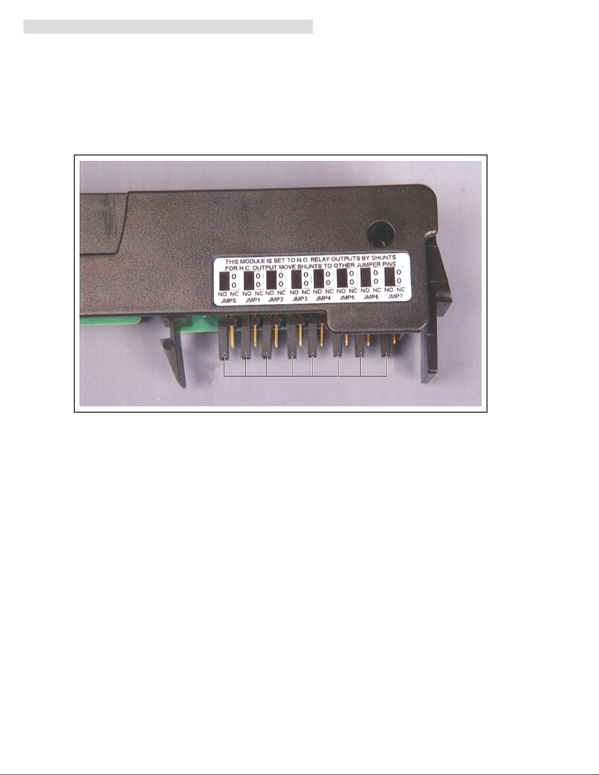
V. Jumper Selection for N.O. or N.C. Relay Contact
The following is a photograph of the normally open (N.O.) or normally closed (N.C.) relay output selection label on the
1492-CM1771-LD012 conversion module.
The 1771-OW relay output module allowed selection of a normally open (N.O.) or normally closed (N.C.) relay contact
output by using a jumper. The 1756-OX8I also provides either N.O. or N.C. relay output selection but by field wire
termination. The 1492-CONCABY is wired to the 1756-OX8I to allow use of either N.O. or N.C. contacts. To select the
N.O. or N.C. relay output type consistent with the initial 1771 configuration simply move the jumper on the conversion
module to the appropriate position, as defined by the selection label. Each output is individually configurable. The default
configuration is the N.O. type.
Jumper 0 through 7
PN-114284
DIR 10000060095 (Version 01)
Publication 1492-IN042B-EN-E
(4)
Page 5
VI. Wiring Diagrams
Conversion: 1771-ID (2) to 1756-IA16I (1)
WARNING
L1
L2
LOAD
1771-WD Swing Arm
From 1771-ID
There are several key application considerations and system specifications (bottom of drawing) when
using these components (conversion module, cable and input module). Read and understand these
considerations before installation.
Conversion Module
1492-CM1771-LD012
L1-0
1
L2-0
2
L1-1
3
L2-1
4
L1-2
5
L2-2
6
L1-3
7
L2-3
8
L1-4
9
L2-4
10
L1-5
11
12
L2-5
1771-WD Swing Arm
From 1771-ID
1
2
3
4
5
JMP0
3
4
N.C.
N.O.
2
1
JMP1
3
4
N.C.
N.O.
2
1
JMP2
3
4
N.C.
N.O.
2
1
JMP3
3
4
N.C.
N.O.
2
1
JMP4
3
4
N.C.
N.O.
2
1
JMP5
3
4
N.C.
N.O.
2
1
JMP6
3
4
N.C.
N.O.
2
1
JMP7
3
4
N.C.
N.O.
2
1
Orange
Blue
6
7
White/Black
8
Red/Black
Green/Black
9
10
Orange/Black
Blue/Black
11
Black/White
12
Red/White
13
Green/White
14
Blue/White
15
Black/Red
16
White/Red
17
Orange/Red
18
Blue/Red
19
Red/Green
20
Orange/Green
21
Black/White/Red
22
23
White/Black/Red
24
Red/Black/White
Green/Black/White
25
26
Orange/Black/White
Blue/Black/White
27
Black/Red/Green
28
White/Red/Green
29
Red/Black/Green
30
Green/Black/Orange
31
Orange/Black/Green
32
Blue/White/Orange
33
Black/White/Orange
34
White/Red/Orange
35
Orange/White/Blue
36
37
Conversion Module
1492-CM1771-LD012
JMP0
4
2
JMP1
4
2
JMP2
L1-6
1
L2-6
2
L1-7
3
L2-7
4
L1-8
5
L2-8
6
L1-9
7
L2-9
8
L1-10
9
L2-10
L1-11
L2-11
10
11
12
L1
L2
LOAD
4
2
JMP3
4
2
JMP4
4
2
JMP5
4
2
JMP6
4
2
JMP7
4
2
Cable
1492-C005005XL 1756-IA16I
CABLE”A”
3
N.C.
N.O.
1
3
N.C.
N.O.
1
3
N.C.
N.O.
1
3
N.C.
N.O.
1
3
N.C.
N.O.
1
3
N.C.
N.O.
1
3
N.C.
N.O.
1
3
N.C.
N.O.
1
1
2
3
4
5
Orange
Blue
6
7
White/Black
8
Red/Black
Green/Black
9
10
Orange/Black
Blue/Black
11
Black/White
12
Red/White
13
Green/White
14
Blue/White
15
Black/Red
16
White/Red
17
Orange/Red
18
Blue/Red
19
Red/Green
20
Orange/Green
21
Black/White/Red
22
23
White/Black/Red
24
Red/Black/White
Green/Black/White
25
26
Orange/Black/White
Blue/Black/White
27
Black/Red/Green
28
White/Red/Green
29
Red/Black/Green
30
Green/Black/Orange
31
Orange/Black/Green
32
Blue/White/Orange
33
Black/White/Orange
34
White/Red/Orange
35
Orange/White/Blue
36
37
CABLE”B”
1
L1-0
2
L2-0
3
L1-1
4
L2-1
5
L1-2
6
L2-2
7
L1-3
8
L2-3
9
L1-4
10
L2-4
11
L1-5
12
L2-5
NOT USED
25
26
NOT USED
NOT USED
27
28
NOT USED
29
NOT USED
NOT USED
30
NOT USED
31
NOT USED
32
NOT USED
33
NOT USED
34
NOT USED
35
NOT USED
36
13
L1-6
14
L2-6
15
L1-7
16
L2-7
17
L1-8
18
L2-8
19
L1-9
20
L2-9
21
L1-10
22
L2-10
23
L1-11
24
L2-11
Conversion Module Installation and Application Considerations
This Bul. 1492 cable consists of a cable wired to one 1756-IA16I RTB. Recommended cable lengths of 0.5M or 1.0M
(005=0.5M, 010=1.0M). See table 2 for other lengths.
The input delay times for the 1771-ID module versus the 1756-IA16I module are as follows:
1771-ID 1756-IA16I w/ 1492-C005005XL
a) Off-to-On Delay 24ms (+/-10ms) 10ms max (plus selectable filter)
b) On-to-Off Delay 24ms (+/-10ms) 8ms max (plus selectable filter)
The 1771-ID module had a jumper selection of N.O. and N.C. outputs. The 1756-IA16I has both N.O. and N.C. outputs, but
selection is by wiring termination on the 1756 swing arm. The 1492-CM1771-LD012 conversion module replaces the functionality
of the 1771-ID jumpers with eight jumpers (JMP0 through JMP7). In the default position, the output will be N.O. If a N.C. output
is required, change the jumper from pins 1-2 to pins 3-4.
Refer to your 1771-ID and 1756-IA16I Installation Manual wiring schematics and diagrams for more details. Ensure 1756
output module ratings are not exceeded. [Reference Doc: 41170-993 (Version 00)]
PN-114284
DIR 10000060095 (Version 01)
Publication 1492-IN042B-EN-E
(5)
Page 6

VI. Wiring Diagrams (Cont’d)
Conversion: 1771-ID01 (2) to 1756-IM16I (1)
WARNING
L1
L2
LOAD
1771-WD Swing Arm
From 1771-ID01
There are several key application considerations and system specifications (bottom of drawing) when
using these components (conversion module, cable and input module). Read and understand these
considerations before installation.
Conversion Module
1492-CM1771-LD012
L1-0
1
L2-0
2
L1-1
3
L2-1
4
L1-2
5
L2-2
6
L1-3
7
L2-3
8
L1-4
9
L2-4
10
L1-5
11
12
L2-5
1771-WD Swing Arm
From 1771-ID01
1
2
3
4
5
JMP0
3
4
N.C.
N.O.
2
1
JMP1
3
4
N.C.
N.O.
2
1
JMP2
3
4
N.C.
N.O.
2
1
JMP3
3
4
N.C.
N.O.
2
1
JMP4
3
4
N.C.
N.O.
2
1
JMP5
3
4
N.C.
N.O.
2
1
JMP6
3
4
N.C.
N.O.
2
1
JMP7
3
4
N.C.
N.O.
2
1
Orange
Blue
6
7
White/Black
8
Red/Black
Green/Black
9
10
Orange/Black
Blue/Black
11
Black/White
12
Red/White
13
Green/White
14
Blue/White
15
Black/Red
16
White/Red
17
Orange/Red
18
Blue/Red
19
Red/Green
20
Orange/Green
21
Black/White/Red
22
23
White/Black/Red
24
Red/Black/White
Green/Black/White
25
26
Orange/Black/White
Blue/Black/White
27
Black/Red/Green
28
White/Red/Green
29
Red/Black/Green
30
Green/Black/Orange
31
Orange/Black/Green
32
Blue/White/Orange
33
Black/White/Orange
34
White/Red/Orange
35
Orange/White/Blue
36
37
Conversion Module
1492-CM1771-LD012
JMP0
4
2
JMP1
4
2
JMP2
L1-6
1
L2-6
2
L1-7
3
L2-7
4
L1-8
5
L2-8
6
L1-9
7
L2-9
8
L1-10
9
L2-10
L1-11
L2-11
10
11
12
L1
L2
LOAD
4
2
JMP3
4
2
JMP4
4
2
JMP5
4
2
JMP6
4
2
JMP7
4
2
Cable
1492-C005005XL
CABLE”A”
1
2
3
4
5
Orange
Blue
6
3
N.C.
7
White/Black
8
N.O.
1
3
N.C.
N.O.
1
3
N.C.
N.O.
1
N.C.
N.O.
1
3
N.C.
N.O.
1
3
N.C.
N.O.
1
N.C.
N.O.
1
N.C.
N.O.
1
3
3
3
Red/Black
Green/Black
9
10
Orange/Black
Blue/Black
11
Black/White
12
Red/White
13
Green/White
14
Blue/White
15
Black/Red
16
White/Red
17
Orange/Red
18
Blue/Red
19
Red/Green
20
Orange/Green
21
Black/White/Red
22
23
White/Black/Red
24
Red/Black/White
Green/Black/White
25
26
Orange/Black/White
Blue/Black/White
27
Black/Red/Green
28
White/Red/Green
29
Red/Black/Green
30
Green/Black/Orange
31
Orange/Black/Green
32
Blue/White/Orange
33
Black/White/Orange
34
White/Red/Orange
35
Orange/White/Blue
36
37
CABLE”B”
1756-IM16I
1
L1-0
2
L2-0
3
L1-1
4
L2-1
5
L1-2
6
L2-2
7
L1-3
8
L2-3
9
L1-4
10
L2-4
11
L1-5
12
L2-5
NOT USED
25
26
NOT USED
NOT USED
27
28
NOT USED
29
NOT USED
NOT USED
30
NOT USED
31
NOT USED
32
NOT USED
33
NOT USED
34
NOT USED
35
NOT USED
36
13
L1-6
14
L2-6
15
L1-7
16
L2-7
17
L1-8
18
L2-8
19
L1-9
20
L2-9
21
L1-10
22
L2-10
23
L1-11
24
L2-11
Conversion Module Installation and Application Considerations
This Bul. 1492 cable consists of 2 separate cables (cable “A” and cable “B”) wired to one 1756-IM16I RTB. Each cable can be either
0.5M or 1.0M (005=0.5M, 010=1.0M). Ensure that cable A and cable B are connected to the correct module in the conversion
The input delay times for the 1771-IM module versus the 1756-IM16I module are as follows:
1771-ID01 1756-IM16I w/ 1492-C005005XL
a) Off-to-On Delay 20ms (+/-10ms) 10ms max (plus selectable filter)
b) On-to-Off Delay 20ms (+/-10ms) 8ms max (plus selectable filter)
The 1771-ID01module had a jumper selection of N.O. and N.C. outputs. The 1756-IM16I has both N.O. and N.C. outputs, but
selection is by wiring termination on the 1756 swing arm. The 1492-CM1771-LD012 conversion module replaces the functionality
of the 1771-ID01 jumpers with eight jumpers (JMP0 through JMP7). In the default position, the output will be N.O. If a N.C. output is
required, change the jumper from pins 1-2 to pins 3-4.
Refer to your 1771-ID01 and 1756-IM16I Installation Manual wiring schematics and diagrams for more details. Ensure
1756 output module ratings are not exceeded. [Reference Doc: 41171-015 (Version 00)]
PN-114284
DIR 10000060095 (Version 01)
Publication 1492-IN042B-EN-E
(6)
Page 7

VI. Wiring Diagrams (Cont’d)
Conversion: 1771-OD (2) to 1756-OA16I (1)
WARNING
L1
L2
LOAD
1771-WD Swing Arm
From 1771-OD
There are several key application considerations and system specifications (bottom of drawing) when
using these components (conversion module, cable and input module). Read and understand these
considerations before installation.
Conversion Module
1492-CM1771-LD012
L1-0
1
L2-0
2
L1-1
3
L2-1
4
L1-2
5
L2-2
6
L1-3
7
L2-3
8
L1-4
9
L2-4
10
L1-5
11
12
L2-5
1771-WD Swing Arm
From 1771-OD
1
2
3
4
5
JMP0
3
4
N.C.
N.O.
2
1
JMP1
3
4
N.C.
N.O.
2
1
JMP2
3
4
N.C.
N.O.
2
1
JMP3
3
4
N.C.
N.O.
2
1
JMP4
3
4
N.C.
N.O.
2
1
JMP5
3
4
N.C.
N.O.
2
1
JMP6
3
4
N.C.
N.O.
2
1
JMP7
3
4
N.C.
N.O.
2
1
Orange
Blue
6
7
White/Black
8
Red/Black
Green/Black
9
10
Orange/Black
Blue/Black
11
Black/White
12
Red/White
13
Green/White
14
Blue/White
15
Black/Red
16
White/Red
17
Orange/Red
18
Blue/Red
19
Red/Green
20
Orange/Green
21
Black/White/Red
22
23
White/Black/Red
24
Red/Black/White
Green/Black/White
25
26
Orange/Black/White
Blue/Black/White
27
Black/Red/Green
28
White/Red/Green
29
Red/Black/Green
30
Green/Black/Orange
31
Orange/Black/Green
32
Blue/White/Orange
33
Black/White/Orange
34
White/Red/Orange
35
Orange/White/Blue
36
37
Conversion Module
1492-CM1771-LD012
JMP0
4
2
JMP1
4
2
JMP2
L1-6
1
L2-6
2
L1-7
3
L2-7
4
L1-8
5
L2-8
6
L1-9
7
L2-9
8
L1-10
9
L2-10
L1-11
L2-11
10
11
12
L1
L2
LOAD
4
2
JMP3
4
2
JMP4
4
2
JMP5
4
2
JMP6
4
2
JMP7
4
2
Cable
1492-C005005XM
CABLE”A”
1
2
3
4
5
Orange
Blue
6
3
N.C.
7
White/Black
8
N.O.
1
3
N.C.
N.O.
1
3
N.C.
N.O.
1
N.C.
N.O.
1
3
N.C.
N.O.
1
3
N.C.
N.O.
1
N.C.
N.O.
1
N.C.
N.O.
1
3
3
3
Red/Black
Green/Black
9
10
Orange/Black
Blue/Black
11
Black/White
12
Red/White
13
Green/White
14
Blue/White
15
Black/Red
16
White/Red
17
Orange/Red
18
Blue/Red
19
Red/Green
20
Orange/Green
21
Black/White/Red
22
23
White/Black/Red
24
Red/Black/White
Green/Black/White
25
26
Orange/Black/White
Blue/Black/White
27
Black/Red/Green
28
White/Red/Green
29
Red/Black/Green
30
Green/Black/Orange
31
Orange/Black/Green
32
Blue/White/Orange
33
Black/White/Orange
34
White/Red/Orange
35
Orange/White/Blue
36
37
CABLE”B”
1756-OA16I
1
L2-0
2
L1-0
3
L2-1
4
L1-1
5
L2-2
6
L1-2
7
L2-3
8
L1-3
9
L2-4
10
L1-4
11
L2-5
12
L1-5
NOT USED
25
26
NOT USED
NOT USED
27
28
NOT USED
29
NOT USED
NOT USED
30
NOT USED
31
NOT USED
32
NOT USED
33
NOT USED
34
NOT USED
35
NOT USED
36
13
L2-6
14
L1-6
15
L2-7
16
L1-7
17
L2-8
18
L1-8
19
L2-9
20
L1-9
21
L2-10
22
L1-10
23
L2-11
24
L1-11
Conversion Module Installation and Application Considerations
This Bul. 1492 cable consists of 2 separate cables (cable “A” and cable “B”) wired to one 1756-OA16I RTB. Each cable can be either
0.5M or 1.0M (005=0.5M, 010=1.0M). Ensure that cable A and cable B are connected to the correct module in the conversion
The 1771-OD module output resistive current limits versus 1756-OA16I limits are as follows:
1771-OD 1756-OA16I w/ 1492-C005005XM
a) Current/Point 2A 2A
b) Current/Module 6A 5A
c) Surge Current/Point 20A for 100ms 20A for 43ms
The 1771-OD module had a jumper selection of N.O. and N.C. outputs. The 1756-OA16I has both N.O. and N.C. outputs, but
selection is by wiring termination on the 1756 swing arm. The 1492-CM1771-LD012 conversion module replaces the functionality
of the 1771-OD jumpers with eight jumpers (JMP0 through JMP7). In the default position, the output will be N.O. If a N.C. output is
required, change the jumper from pins 1-2 to pins 3-4.
Refer to your 1771-OD and 1756-OA16I Installation Manual wiring schematics and diagrams for more details. Ensure 1756 output
module ratings are not exceeded. [Reference Doc: 41170-994 (Version 00)]
PN-114284
DIR 10000060095 (Version 01)
Publication 1492-IN042B-EN-E
(7)
Page 8

VI. Wiring Diagrams (Cont’d)
Conversion: 1771-ODZ (2) to 1756-OA16I (1)
WARNING
LOAD
LOAD
LOAD
LOAD
Out-0 N.O./N.C.
Out-1 N.O./N.C.
Out-2 N.O./N.C.
Out-3 N.O./N.C.
Out-4 N.O./N.C.
Out-6 N.O./N.C.
Out-0 N.O./N.C.
Out-1 N.O./N.C.
Out-2 N.O./N.C.
Out-3 N.O./N.C.
Out-4 N.O./N.C.
Out-6 N.O./N.C.
L1
L2
+
-
1771-WD Swing Arm
From 1771-ODZ
L1
L2
+
-
1771-WD Swing Arm
From 1771-ODZ
There are several key application considerations and system specifications (bottom of drawing) when
using these components (conversion module, cable and input module). Read and understand these
considerations before installation.
Conversion Module
1492-CM1771-LD012
+V0/1
+V2/3
+V4/5
Out-5 N.O./N.C.
+V6/7
Out-7 N.O./N.C.
+V0/1
+V2/3
+V4/5
Out-5 N.O./N.C.
+V6/7
Out-7 N.O./N.C.
JMP0
3
4
N.C.
N.O.
2
1
JMP1
3
4
N.C.
N.O.
2
1
JMP2
3
4
1
2
3
4
5
6
7
8
9
10
11
12
N.C.
N.O.
2
1
JMP3
3
4
N.C.
N.O.
2
1
JMP4
3
4
N.C.
N.O.
2
1
JMP5
3
4
N.C.
N.O.
2
1
JMP6
3
4
N.C.
N.O.
2
1
JMP7
3
4
N.C.
N.O.
2
1
Conversion Module
1492-CM1771-LD012
JMP0
3
4
N.C.
N.O.
2
1
JMP1
3
4
N.C.
N.O.
2
1
JMP2
3
4
1
2
3
4
5
6
7
8
9
10
11
12
N.C.
N.O.
2
1
JMP3
3
4
N.C.
N.O.
2
1
JMP4
3
4
N.C.
N.O.
2
1
JMP5
3
4
N.C.
N.O.
2
1
JMP6
3
4
N.C.
N.O.
2
1
JMP7
3
4
N.C.
N.O.
2
1
1
2
3
1492-CONCAB005Y
4
5
Orange
Blue
6
7
White/Black
8
Red/Black
Green/Black
9
10
Orange/Black
Blue/Black
11
Black/White
12
Red/White
13
Green/White
14
Blue/White
15
Black/Red
16
White/Red
17
Orange/Red
18
Blue/Red
19
Red/Green
20
Orange/Green
21
Black/White/Red
22
23
White/Black/Red
24
Red/Black/White
Green/Black/White
25
26
Orange/Black/White
Blue/Black/White
27
Black/Red/Green
28
White/Red/Green
29
Red/Black/Green
30
Green/Black/Orange
31
Orange/Black/Green
32
Blue/White/Orange
33
Black/White/Orange
34
White/Red/Orange
35
Orange/White/Blue
36
37
1
2
3
4
5
Orange
Blue
6
7
White/Black
8
Red/Black
Green/Black
9
10
Orange/Black
Blue/Black
11
Black/White
12
Red/White
13
Green/White
14
Blue/White
15
Black/Red
16
White/Red
17
Orange/Red
18
Blue/Red
19
Red/Green
20
Orange/Green
21
Black/White/Red
22
23
White/Black/Red
24
Red/Black/White
Green/Black/White
25
26
Orange/Black/White
Blue/Black/White
27
Black/Red/Green
28
White/Red/Green
29
Red/Black/Green
30
Green/Black/Orange
31
Orange/Black/Green
32
Blue/White/Orange
33
Black/White/Orange
34
White/Red/Orange
35
Orange/White/Blue
36
37
Cable
1492-C005005XP 1756-OA16I
CABLE”A”
2
L1-0
4
L1-0
1
L2-0
3
L2-1
6
L1-1
8
L1-1
5
L2-2
7
L2-3
10
L1-2
12
L1-2
9
L2-4
11
L2-5
14
L1-3
16
L1-3
13
L2-6
15
L2-7
NOT USED
33
NOT USED
34
NOT USED
35
NOT USED
36
CABLE”B”
18
L1-4
20
L1-4
17
L2-8
19
L2-9
22
L1-5
24
L1-5
21
L2-10
23
L2-11
26
L1-4
28
L1-6
25
L2-12
27
L2-13
30
L1-7
32
L1-7
29
L2-14
31
L2-15
Conversion Module Installation and Application Considerations
This Bul. 1492 cable consists of 2 separate cables (cable “A” and cable “B”) wired to one 1756-OA16I RTB. Each cable can be either
0.5M or 1.0M (005=0.5M, 010=1.0M). Ensure that cable A and cable B are connected to the correct module in the conversion
The 1771-ODZ module output resistive current limits versus 1756-OA16I limits are as follows:
1771-ODZ 1756-OA16I w/ 1492-C005005XP
a) Current/Point 2A 2A
b) Current/Module 6A 5A @ 60°C
c) Surge Current/Point 20A for 100ms 20A for 43ms
The 1771-ODZ module had a jumper selection of N.O. and N.C. outputs. The 1756-OA16I has both N.O. and N.C. outputs, but
selection is by wiring termination on the 1756 swing arm. The 1492-CM1771-LD012 conversion module replaces the functionality
of the 1771-ODZ jumpers with eight jumpers (JMP0 through JMP7). In the default position, the output will be N.O. If a N.C. output is
required, change the jumper from pins 1-2 to pins 3-4.
Refer to your 1771-ODZ and 1756-OA16I Installation Manual wiring schematics and diagrams for more details. Ensure 1756 output
module ratings are not exceeded. [Reference Doc: 41171-016 (Version 00)]
PN-114284
DIR 10000060095 (Version 01)
Publication 1492-IN042B-EN-E
(8)
Page 9

VI. Wiring Diagrams (Cont’d)
Conversion: 1771-OR (2) to 1756-OA16I (1)
WARNING
L2
L1
LOAD
1771-WD Swing Arm
From 1771-OR
L2
L1
LOAD
1771-WD Swing Arm
From 1771-OR
There are several key application considerations and system specifications (bottom of drawing) when
using these components (conversion module, cable and input module). Read and understand these
considerations before installation.
Conversion Module
1492-CM1771-LD012
1
0-IN
2
0-OUT
3
1-IN
4
1-OUT
5
2-IN
6
2-OUT
7
3-IN
8
3-OUT
9
4-IN
10
4-OUT
11
5-IN
12
5-OUT
Conversion Module
1492-CM1771-LD012
6-IN
1
6-OUT
2
7-IN
3
7-OUT
4
8-IN
5
6
8-OUT
7
9-IN
8
9-OUT
9
10-IN
10
10-OUT
11
11-IN
12
11-OUT
1
2
3
1492-CONCAB005Y
4
5
JMP0
3
4
N.C.
N.O.
2
1
JMP1
3
4
N.C.
N.O.
2
1
JMP2
3
4
N.C.
N.O.
2
1
JMP3
3
4
N.C.
N.O.
2
1
JMP4
3
4
N.C.
N.O.
2
1
JMP5
3
4
N.C.
N.O.
2
1
JMP6
3
4
N.C.
N.O.
2
1
JMP7
3
4
N.C.
N.O.
2
1
JMP0
3
4
N.C.
N.O.
2
1
JMP1
3
4
N.C.
N.O.
2
1
JMP2
3
4
N.C.
N.O.
2
1
JMP3
3
4
N.C.
N.O.
2
1
JMP4
3
4
N.C.
N.O.
2
1
JMP5
3
4
N.C.
N.O.
2
1
JMP6
3
4
N.C.
N.O.
2
1
JMP7
3
4
N.C.
N.O.
2
1
Orange
Blue
6
7
White/Black
8
Red/Black
Green/Black
9
10
Orange/Black
Blue/Black
11
Black/White
12
Red/White
13
Green/White
14
Blue/White
15
Black/Red
16
White/Red
17
Orange/Red
18
Blue/Red
19
Red/Green
20
Orange/Green
21
Black/White/Red
22
23
White/Black/Red
24
Red/Black/White
Green/Black/White
25
26
Orange/Black/White
Blue/Black/White
27
Black/Red/Green
28
White/Red/Green
29
Red/Black/Green
30
Green/Black/Orange
31
Orange/Black/Green
32
Blue/White/Orange
33
Black/White/Orange
34
White/Red/Orange
35
Orange/White/Blue
36
37
1
2
3
4
5
Orange
Blue
6
7
White/Black
8
Red/Black
Green/Black
9
10
Orange/Black
Blue/Black
11
Black/White
12
Red/White
13
Green/White
14
Blue/White
15
Black/Red
16
White/Red
17
Orange/Red
18
Blue/Red
19
Red/Green
20
Orange/Green
21
Black/White/Red
22
23
White/Black/Red
24
Red/Black/White
Green/Black/White
25
26
Orange/Black/White
Blue/Black/White
27
Black/Red/Green
28
White/Red/Green
29
Red/Black/Green
30
Green/Black/Orange
31
Orange/Black/Green
32
Blue/White/Orange
33
Black/White/Orange
34
White/Red/Orange
35
Orange/White/Blue
36
37
Cable
1492-C005005XR 1756-OA16I
CABLE ”A”
2
L2-0
1
L1-0
3
L1-1
5
L1-2
4
L2-1
6
L2-2
8
L2-3
9
L1-3
11
L1-4
13
L1-5
10
L2-4
12
L2-5
NOT USED
26
NOT USED
27
NOT USED
28
NOT USED
29
NOT USED
30
NOT USED
31
NOT USED
32
NOT USED
33
34
NOT USED
NOT USED
35
NOT USED
36
CABLE ”B”
14
L2-6
15
L1-6
17
L1-7
19
L1-8
16
L2-7
18
L2-8
20
L2-9
21
L1-9
23
L1-10
25
L1-11
22
L2-10
24
L2-11
Conversion Module Installation and Application Considerations
This Bul. 1492 cable consists of 2 separate cables (cable “A” and cable “B”) wired to one 1756-OA16I RTB. Each cable can be either
0.5M or 1.0M (005=0.5M, 010=1.0M). Ensure that cable A and cable B are connected to the correct module in the conversion
The 1771-OR module output resistive current limits versus 1756-OA16I limits are as follows:
1771-OR 1756-OA16I w/ 1492-C005005XR
a) Current/Point 2A 2A
b) Current/Module 6A 5A @ 60°C
c) Surge Current/Point 15A for 100ms 20A for 43ms
The 1771-OR module had a jumper selection of N.O. and N.C. outputs. The 1756-OA16I has both N.O. and N.C. outputs, but
selection is by wiring termination on the 1756 swing arm. The 1492-CM1771-LD012 conversion module replaces the functionality
of the 1771-OR jumpers with eight jumpers (JMP0 through JMP7). In the default position, the output will be N.O. If a N.C. output is
required, change the jumper from pins 1-2 to pins 3-4.
Refer to your 1771-OR and 1756-OA16I Installation Manual wiring schematics and diagrams for more details. Ensure 1756 output
module ratings are not exceeded. [Reference Doc: 41171-017 (Version 00)]
PN-114284
DIR 10000060095 (Version 01)
Publication 1492-IN042B-EN-E
(9)
Page 10

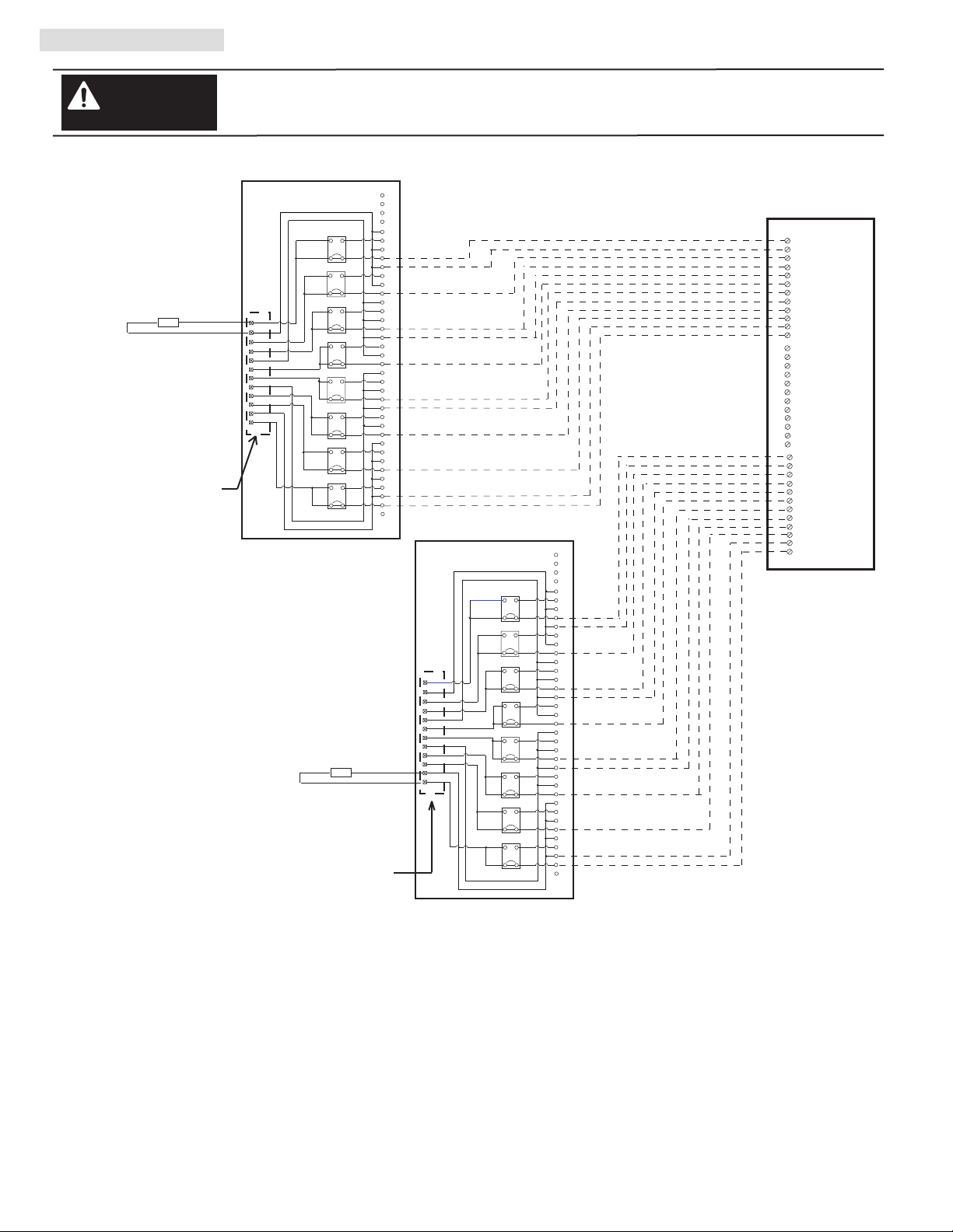
VI. Wiring Diagrams (Cont’d)
Conversion: 1771-OW to 1756-OX8I
WARNING
L1
L2
LOAD
+
LOAD
-
There are several key application considerations and system specifications (bottom of drawing) when
using these components (conversion module, cable and input module). Read and understand these
considerations before installation.
Out-0 N.O./N.C.
+V0/1
Out-1 N.O./N.C.
Out-2 N.O./N.C.
+V2/3
Out-3 N.O./N.C.
Out-4 N.O./N.C.
+V4/5
Out-5 N.O./N.C.
Out-6 N.O./N.C.
+V6/7
Out-7 N.O./N.C.
Conversion Module
1492-CM1771-LD012
1
2
3
1492-CONCAB005Y
4
Orange
JMP0
3
4
N.C.
N.O.
2
1
JMP1
3
4
N.C.
N.O.
2
1
JMP2
3
4
2
JMP3
4
2
JMP4
4
2
JMP5
4
2
JMP6
4
2
JMP7
4
2
N.C.
N.O.
1
3
N.C.
N.O.
1
3
N.C.
N.O.
1
3
N.C.
N.O.
1
3
N.C.
N.O.
1
3
N.C.
N.O.
1
1
2
3
4
5
6
7
8
9
10
11
12
5
Blue
6
White/Black
7
8
Red/Black
9
Green/Black
Orange/Black
10
Blue/Black
11
Black/White
12
Red/White
13
Green/White
14
Blue/White
15
Black/Red
16
17
White/Red
18
Orange/Red
Blue/Red
19
20
Red/Green
21
Orange/Green
22
Black/White/Red
23
White/Black/Red
24
Red/Black/White
Green/Black/White
25
Orange/Black/White
26
Blue/Black/White
27
Black/Red/Green
28
White/Red/Green
29
Red/Black/Green
30
Green/Black/Orange
31
Orange/Black/Green
32
Blue/White/Orange
33
34
Black/White/Orange
White/Red/Orange
35
36
Orange/White/Blue
37
Cable
2
1
4
3
6
5
8
7
10
9
12
11
14
13
16
15
18
17
20
19
22
21
24
23
26
25
28
27
30
29
32
31
1756-OX8I
L1-0
OUT-0 N.C.
L1-0
OUT-0 N.O.
L1-1
OUT-1 N.C.
L1-1
OUT-1 N.O.
L1-2
OUT-2 N.C.
L1-2
OUT-2 N.O.
L1-3
OUT-3 N.C.
L1-3
OUT-3 N.O.
L1-4
OUT-4 N.C.
L1-4
OUT-4 N.O.
L1-5
OUT-5 N.C.
L1-5
OUT-5 N.O.
L1-6
OUT-6 N.C.
L1-6
OUT-6 N.O.
L1-7
OUT-7 N.C.
L1-7
OUT-7 N.O.
1771-WD Swing Arm
From 1771-OW
Conversion Module Installation and Application Considerations
This Bul. 1492 cable consists of a cable wired to one 1756-OX8I RTB. Recommended cable lengths of 0.5M or 1.0M (005=0.5M),
010=1.0M). See table 2 for other lengths.
The 1771-OW module output resistive current limits versus 1756-OX8I limits are as follows:
(NOTE: For switching and inductive current ratings, refer to the modules Installation Instructions)
1771-OW 1756-OX8I w/ 1492-CONCAB005Y
a) Current/Point 0.2A @ 138V AC 2A @ 240V AC
1A @ 30V DC 2A @ 30V DC
0.25A @ 125V DC 0.25A @ 125V DC
The 1771-OW module had a jumper selection of N.O. and N.C. outputs. The 1756-OX8I has both N.O. and N.C. outputs, but
selection is by wiring termination on the 1756 swing arm. The 1492-CM1771-LD012 conversion module replaces the functionality
of the 1771-OW jumpers with eight jumpers (JMP0 through JMP7). In the default position, the output will be N.O. If a N.C. output is
required, change the jumper from pins 1-2 to pins 3-4.
Refer to your 1771-OW and 1756-OX8I Installation Manual wiring schematics and diagrams for more details. Ensure 1756 output
module ratings are not exceeded. [Reference Doc: 41170-941 (Version 01)]
PN-114284
DIR 10000060095 (Version 01)
Publication 1492-IN042B-EN-E
(10)
Page 11

VI. Wiring Diagrams (Cont’d)
Conversion: 1771-OY to 1756-OX8I
WARNING
L1
LOAD
L2
+
LOAD
-
1771-WD Swing Arm
From 1771-OY
Out-0 N.O./N.C.
+V0/1
Out-1 N.O./N.C.
Out-2 N.O./N.C.
+V2/3
Out-3 N.O./N.C.
Out-4 N.O./N.C.
+V4/5
Out-5 N.O./N.C.
Out-6 N.O./N.C.
+V6/7
Out-7 N.O./N.C.
There are several key application considerations and system specifications (bottom of drawing) when
using these components (conversion module, cable and input module). Read and understand these
considerations before installation.
Conversion Module
1492-CM1771-LD012
1
2
3
4
JMP0
3
4
N.C.
N.O.
2
1
JMP1
3
4
N.C.
N.O.
2
1
JMP2
3
4
2
4
2
4
2
4
2
4
2
4
2
JMP3
JMP4
JMP5
JMP6
JMP7
N.C.
N.O.
1
3
N.C.
N.O.
1
3
N.C.
N.O.
1
3
N.C.
N.O.
1
3
N.C.
N.O.
1
3
N.C.
N.O.
1
1
2
3
4
5
6
7
8
9
10
11
12
5
6
7
8
9
10
11
12
13
14
15
16
17
18
19
20
21
22
23
24
25
26
27
28
29
30
31
32
33
34
35
36
37
1492-CONCAB005Y 1756-OX8I
Orange
Blue
White/Black
Red/Black
Green/Black
Orange/Black
Blue/Black
Black/White
Red/White
Green/White
Blue/White
Black/Red
White/Red
Orange/Red
Blue/Red
Red/Green
Orange/Green
Black/White/Red
White/Black/Red
Red/Black/White
Green/Black/White
Orange/Black/White
Blue/Black/White
Black/Red/Green
White/Red/Green
Red/Black/Green
Green/Black/Orange
Orange/Black/Green
Blue/White/Orange
Black/White/Orange
White/Red/Orange
Orange/White/Blue
Cable
2
1
4
3
6
5
8
7
10
9
12
11
14
13
16
15
18
17
20
19
22
21
24
23
26
25
28
27
30
29
32
31
L1-0
OUT-0 N.C.
L1-0
OUT-0 N.O.
L1-1
OUT-1 N.C.
L1-1
OUT-1 N.O.
L1-2
OUT-2 N.C.
L1-2
OUT-2 N.O.
L1-3
OUT-3 N.C.
L1-3
OUT-3 N.O.
L1-4
OUT-4 N.C.
L1-4
OUT-4 N.O.
L1-5
OUT-5 N.C.
L1-5
OUT-5 N.O.
L1-6
OUT-6 N.C.
L1-6
OUT-6 N.O.
L1-7
OUT-7 N.C.
L1-7
OUT-7 N.O.
Conversion Module Installation and Application Considerations
This Bul. 1492 cable consists of a cable wired to one 1756-OX8I RTB. Recommended cable lengths of 0.5M or 1.0M (005=0.5M),
010=1.0M). See table 2 for other lengths.
The 1771-OY module output resistive current limits versus 1756-OX8I limits are as follows:
(NOTE: For switching and inductive current ratings, refer to the modules Installation Instructions)
1771-OY 1756-OX8I w/ 1492-CONCAB005Y
a) Current/Point 100mA @ 138V AC 2A @ 240V AC
100mA @ 125V DC 2A @ 30V DC
0.25A @ 125V DC
The 1771-OY module had a jumper selection of N.O. and N.C. outputs. The 1756-OX8I has both N.O. and N.C. outputs, but
selection is by wiring termination on the 1756 swing arm. The 1492-CM1771-LD012 conversion module replaces the functionality
of the 1771-OY jumpers with eight jumpers (JMP0 through JMP7). In the default position, the output will be N.O. If a N.C. output is
required, change the jumper from pins 1-2 to pins 3-4.
Refer to your 1771-OY and 1756-OX8I Installation Manual wiring schematics and diagrams for more details. Ensure 1756 output
module ratings are not exceeded. [Reference Doc: 41171-011 (Version 00)]
PN-114284
DIR 10000060095 (Version 01)
Publication 1492-IN042B-EN-E
(11)
Page 12

VI. Wiring Diagrams (Cont’d)
Conversion: 1771-OYL to 1756-OX8I
WARNING
L1
LOAD
L2
+
LOAD
-
1771-WD Swing Arm
From 1771-OYL
There are several key application considerations and system specifications (bottom of drawing) when
using these components (conversion module, cable and input module). Read and understand these
considerations before installation.
Out-0 N.O./N.C.
+V0/1
Out-1 N.O./N.C.
Out-2 N.O./N.C.
+V2/3
Out-3 N.O./N.C.
Out-4 N.O./N.C.
+V4/5
Out-5 N.O./N.C.
Out-6 N.O./N.C.
+V6/7
Out-7 N.O./N.C.
Conversion Module
1492-CM1771-LD012
1
2
3
4
JMP0
3
4
N.C.
N.O.
2
1
JMP1
3
4
N.C.
N.O.
2
1
JMP2
3
4
2
4
2
4
2
4
2
4
2
4
2
JMP3
JMP4
JMP5
JMP6
JMP7
N.C.
N.O.
1
3
N.C.
N.O.
1
3
N.C.
N.O.
1
3
N.C.
N.O.
1
3
N.C.
N.O.
1
3
N.C.
N.O.
1
1
2
3
4
5
6
7
8
9
10
11
12
5
6
7
8
9
10
11
12
13
14
15
16
17
18
19
20
21
22
23
24
25
26
27
28
29
30
31
32
33
34
35
36
37
1492-CONCAB005Y 1756-OX8I
Orange
Blue
White/Black
Red/Black
Green/Black
Orange/Black
Blue/Black
Black/White
Red/White
Green/White
Blue/White
Black/Red
White/Red
Orange/Red
Blue/Red
Red/Green
Orange/Green
Black/White/Red
White/Black/Red
Red/Black/White
Green/Black/White
Orange/Black/White
Blue/Black/White
Black/Red/Green
White/Red/Green
Red/Black/Green
Green/Black/Orange
Orange/Black/Green
Blue/White/Orange
Black/White/Orange
White/Red/Orange
Orange/White/Blue
Cable
2
1
4
3
6
5
8
7
10
9
12
11
14
13
16
15
18
17
20
19
22
21
24
23
26
25
28
27
30
29
32
31
L1-0
OUT-0 N.C.
L1-0
OUT-0 N.O.
L1-1
OUT-1 N.C.
L1-1
OUT-1 N.O.
L1-2
OUT-2 N.C.
L1-2
OUT-2 N.O.
L1-3
OUT-3 N.C.
L1-3
OUT-3 N.O.
L1-4
OUT-4 N.C.
L1-4
OUT-4 N.O.
L1-5
OUT-5 N.C.
L1-5
OUT-5 N.O.
L1-6
OUT-6 N.C.
L1-6
OUT-6 N.O.
L1-7
OUT-7 N.C.
L1-7
OUT-7 N.O.
Conversion Module Installation and Application Considerations
This Bul. 1492 cable consists of a cable wired to one 1756-OX8I RTB. Recommended cable lengths of 0.5M or 1.0M (005=0.5M),
010=1.0M). See table 2 for other lengths.
The 1771-OYL module output resistive current limits versus 1756-OX8I limits are as follows:
(NOTE: For switching and inductive current ratings, refer to the modules Installation Instructions)
1771-OYL 1756-OX8I w/ 1492-CONCAB005Y
a) Current/Point 100mA @ 24V AC 2A @ 240V AC
100mA @ 24V DC 2A @ 30V DC
0.25A @ 125V DC
The 1771-OYL module had a jumper selection of N.O. and N.C. outputs. The 1756-OX8I has both N.O. and N.C. outputs, but
selection is by wiring termination on the 1756 swing arm. The 1492-CM1771-LD012 conversion module replaces the functionality
of the 1771-OYL jumpers with eight jumpers (JMP0 through JMP7). In the default position, the output will be N.O. If a N.C. output is
required, change the jumper from pins 1-2 to pins 3-4.
Refer to your 1771-OYL and 1756-OX8I Installation Manual wiring schematics and diagrams for more details. Ensure 1756 output
module ratings are not exceeded. [Reference Doc: 41171-012 (Version 00)]
PN-114284
DIR 10000060095 (Version 01)
Publication 1492-IN042B-EN-E
(12)
Page 13

VI. Wiring Diagrams (Cont’d)
Conversion: 1771-OZ to 1756-OX8I
L1
L2
+
-
WARNING
Out-0 N.O./N.C.
LOAD
LOAD
Out-1 N.O./N.C.
Out-2 N.O./N.C.
Out-3 N.O./N.C.
Out-4 N.O./N.C.
Out-5 N.O./N.C.
Out-6 N.O./N.C.
Out-7 N.O./N.C.
There are several key application considerations and system specifications (bottom of drawing) when
using these components (conversion module, cable and input module). Read and understand these
considerations before installation.
Conversion Module
1492-CM1771-LD012
1
+V0/1
+V2/3
+V4/5
+V6/7
2
3
4
JMP0
3
4
N.C.
N.O.
2
1
JMP1
3
4
N.C.
N.O.
2
1
JMP2
3
4
2
4
2
4
2
4
2
4
2
4
2
JMP3
JMP4
JMP5
JMP6
JMP7
N.C.
N.O.
1
3
N.C.
N.O.
1
3
N.C.
N.O.
1
3
N.C.
N.O.
1
3
N.C.
N.O.
1
3
N.C.
N.O.
1
1
2
3
4
5
6
7
8
9
10
11
12
5
6
7
8
9
10
11
12
13
14
15
16
17
18
19
20
21
22
23
24
25
26
27
28
29
30
31
32
33
34
35
36
37
1492-CONCAB005Y 1756-OX8I
Orange
Blue
White/Black
Red/Black
Green/Black
Orange/Black
Blue/Black
Black/White
Red/White
Green/White
Blue/White
Black/Red
White/Red
Orange/Red
Blue/Red
Red/Green
Orange/Green
Black/White/Red
White/Black/Red
Red/Black/White
Green/Black/White
Orange/Black/White
Blue/Black/White
Black/Red/Green
White/Red/Green
Red/Black/Green
Green/Black/Orange
Orange/Black/Green
Blue/White/Orange
Black/White/Orange
White/Red/Orange
Orange/White/Blue
Cable
2
1
4
3
6
5
8
7
10
9
12
11
14
13
16
15
18
17
20
19
22
21
24
23
26
25
28
27
30
29
32
31
L1-0
OUT-0 N.C.
L1-0
OUT-0 N.O.
L1-1
OUT-1 N.C.
L1-1
OUT-1 N.O.
L1-2
OUT-2 N.C.
L1-2
OUT-2 N.O.
L1-3
OUT-3 N.C.
L1-3
OUT-3 N.O.
L1-4
OUT-4 N.C.
L1-4
OUT-4 N.O.
L1-5
OUT-5 N.C.
L1-5
OUT-5 N.O.
L1-6
OUT-6 N.C.
L1-6
OUT-6 N.O.
L1-7
OUT-7 N.C.
L1-7
OUT-7 N.O.
1771-WD Swing Arm
From 1771-OZ
Conversion Module Installation and Application Considerations
This Bul. 1492 cable consists of a cable wired to one 1756-OX8I RTB. Recommended cable lengths of 0.5M or 1.0M (005=0.5M),
010=1.0M). See table 2 for other lengths.
The 1771-OZ module output resistive current limits versus 1756-OX8I limits are as follows:
(NOTE: For switching and inductive current ratings, refer to the modules Installation Instructions)
1771-OZ 1756-OX8I w/ 1492-CONCAB005Y
a) Current/Point 100mA @ 138V AC 2A @ 240V AC
100mA @ 138V DC 2A @ 30V DC
0.25A @ 125V DC
The 1771-OZ module had a jumper selection of N.O. and N.C. outputs. The 1756-OX8I has both N.O. and N.C. outputs, but
selection is by wiring termination on the 1756 swing arm. The 1492-CM1771-LD012 conversion module replaces the functionality
of the 1771-OZ jumpers with eight jumpers (JMP0 through JMP7). In the default position, the output will be N.O. If a N.C. output is
required, change the jumper from pins 1-2 to pins 3-4.
Refer to your 1771-OZ and 1756-OX8I Installation Manual wiring schematics and diagrams for more details. Ensure 1756 output
module ratings are not exceeded. [Reference Doc: 41171-013 (Version 00)]
PN-114284
DIR 10000060095 (Version 01)
Publication 1492-IN042B-EN-E
(13)
Page 14

VI. Wiring Diagrams (Cont’d)
Conversion: 1771-OZL to 1756-OX8I
WARNING
There are several key application considerations and system specifications (bottom of drawing) when
using these components (conversion module, cable and input module). Read and understand these
considerations before installation.
Conversion Module
1492-CM1771-LD012
1
2
3
4
JMP0
3
4
N.C.
N.O.
2
1
JMP1
3
4
N.C.
N.O.
2
1
JMP2
3
4
2
4
2
4
2
4
2
4
2
4
2
JMP3
JMP4
JMP5
JMP6
JMP7
N.C.
N.O.
1
3
N.C.
N.O.
1
3
N.C.
N.O.
1
3
N.C.
N.O.
1
3
N.C.
N.O.
1
3
N.C.
N.O.
1
L1
LOAD
L2
+
LOAD
-
Out-0 N.O./N.C.
+V0/1
Out-1 N.O./N.C.
Out-2 N.O./N.C.
+V2/3
Out-3 N.O./N.C.
Out-4 N.O./N.C.
+V4/5
Out-5 N.O./N.C.
Out-6 N.O./N.C.
+V6/7
Out-7 N.O./N.C.
1
2
3
4
5
6
7
8
9
10
11
12
5
6
7
8
9
10
11
12
13
14
15
16
17
18
19
20
21
22
23
24
25
26
27
28
29
30
31
32
33
34
35
36
37
1492-CONCAB005Y 1756-OX8I
Orange
Blue
White/Black
Red/Black
Green/Black
Orange/Black
Blue/Black
Black/White
Red/White
Green/White
Blue/White
Black/Red
White/Red
Orange/Red
Blue/Red
Red/Green
Orange/Green
Black/White/Red
White/Black/Red
Red/Black/White
Green/Black/White
Orange/Black/White
Blue/Black/White
Black/Red/Green
White/Red/Green
Red/Black/Green
Green/Black/Orange
Orange/Black/Green
Blue/White/Orange
Black/White/Orange
White/Red/Orange
Orange/White/Blue
Cable
2
1
4
3
6
5
8
7
10
9
12
11
14
13
16
15
18
17
20
19
22
21
24
23
26
25
28
27
30
29
32
31
L1-0
OUT-0 N.C.
L1-0
OUT-0 N.O.
L1-1
OUT-1 N.C.
L1-1
OUT-1 N.O.
L1-2
OUT-2 N.C.
L1-2
OUT-2 N.O.
L1-3
OUT-3 N.C.
L1-3
OUT-3 N.O.
L1-4
OUT-4 N.C.
L1-4
OUT-4 N.O.
L1-5
OUT-5 N.C.
L1-5
OUT-5 N.O.
L1-6
OUT-6 N.C.
L1-6
OUT-6 N.O.
L1-7
OUT-7 N.C.
L1-7
OUT-7 N.O.
1771-WD Swing Arm
From 1771-OZL
Conversion Module Installation and Application Considerations
This Bul. 1492 cable consists of a cable wired to one 1756-OX8I RTB. Recommended cable lengths of 0.5M or 1.0M (005=0.5M),
010=1.0M). See table 2 for other lengths.
The 1771-OZL module output resistive current limits versus 1756-OX8I limits are as follows:
(NOTE: For switching and inductive current ratings, refer to the modules Installation Instructions)
1771-OZL 1756-OX8I w/ 1492-CONCAB005Y
a) Current/Point 100mA @ 138V AC 2A @ 240V AC
100mA @ 138V DC 2A @ 30V DC
0.25A @ 125V DC
The 1771-OZL module had a jumper selection of N.O. and N.C. outputs. The 1756-OX8I has both N.O. and N.C. outputs, but
selection is by wiring termination on the 1756 swing arm. The 1492-CM1771-LD012 conversion module replaces the functionality
of the 1771-OZL jumpers with eight jumpers (JMP0 through JMP7). In the default position, the output will be N.O. If a N.C. output is
required, change the jumper from pins 1-2 to pins 3-4.
Refer to your 1771-OZL and 1756-OX8I Installation Manual wiring schematics and diagrams for more details. Ensure 1756 output
module ratings are not exceeded. [Reference Doc: 41171-014 (Version 00)]
PN-114284
DIR 10000060095 (Version 01)
Publication 1492-IN042B-EN-E
(14)
Page 15

PN-114284
DIR 10000060095 (Version 01)
Publication 1492-IN042B-EN-E
(15)
Page 16

PN-114284
DIR 10000060095 (Version 01)
Publication 1492-IN042B-EN-E
Printed in U.S.A.
 Loading...