

Page 1
Installation Instructions
Bulletin 1485P KwikLinkt Lite Connectors
Trunk-Line and Branch-Line Pressure-Welded Connectors
IMPORTANT: SAVE THESE INSTRUCTIONS FOR FUTURE USE.
Refer to the product catalog pages for additional information.
Safety Precautions
S Do not pull on the connector or the cable. The connector
may be damaged or the cable conductors may be broken.
S To prevent connector damage and broken cable
conductors, install the cable and connector in locations
where they will not be stepped on, entangled in people’s
legs, or otherwise subjected to excessive strain. If
installation in such locations cannot be avoided, install
protective covers to protect the connector and cable.
S Do not mate the connector in the wrong direction. The
connector may be damaged.
S Do not use the connector if the lock lever is broken. The
connector may become disconnected, possibly causing
machine malfunction.
S When installing the cable, do not bend it past the
specifications given for the cable.
S Do not apply a current exceeding the rated current.
S Do not use pliers or similar tools to remove the connector.
S Hold the connector firmly when working on it, but do not
apply excessive force to it.
S Once a connector has been assembled do not take it apart
and reuse it. If the assembly is not successful, use a new
connector to redo the operation.
S This connector is not water-proof. Do not allow it to be
subjected to water or oil during operation.
Trunk-Line Connector
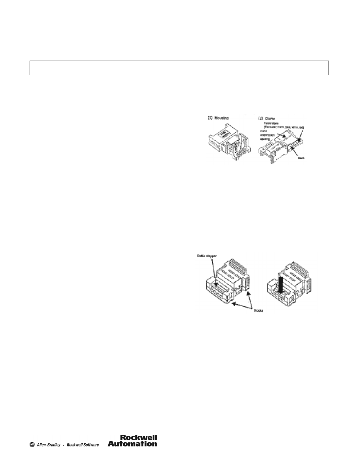
Part Names
1485P--K1TG4
Wiring Procedure
1. Cutting the Cable
S Cut expansion cables perpendicular to the length of the
cable.
S To prevent short-circuits, cut the cable with a sharp
instrument and be sure there are no whiskers on the
conductors.
2. Assembling the Cable Stopper (for expansion)
S Align the cover and catch the hooks and then press the
cable stopper until it clicks into place and stays in place.
Precautions for Correct Use
S Wiring Work
S Do not perform wiring work or connect/disconnect the
connector while the power supply is ON. Electrical
shock or machine malfunction may result.
S Wiring the cable according to the wiring diagram for the
machine being used.
S Confirm that there are no short-circuits caused by wires
sticking out of the connector.
S Connecting the Connector
S Always hold onto the body of the connector when
connecting/disconnecting the connector.
S Be sure the connector is connected completely to the
back and then pull in the reverse direction to be sure the
connector will not disconnect.
S Confirm that the cable labels and cable colors match
before connecting the cable.
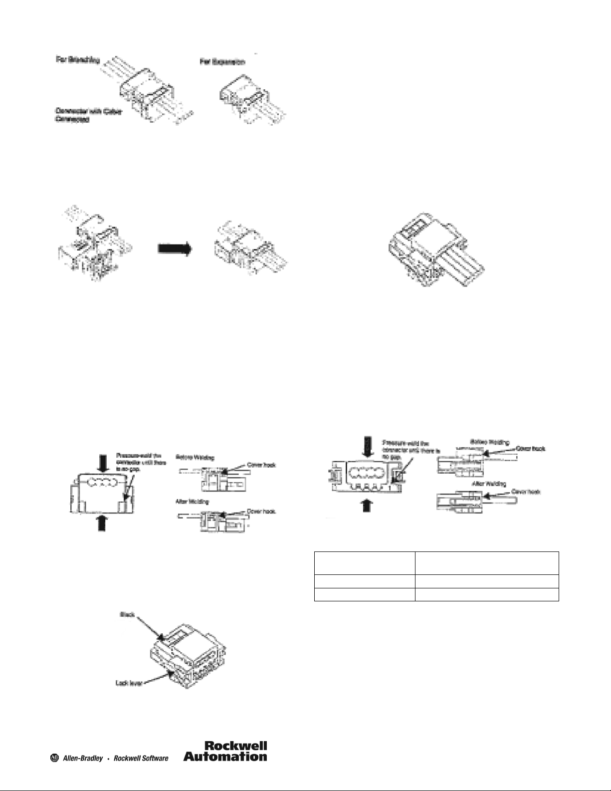
3. Connecting the Cable
S Align the cable labels and cable colors and place the cable
in the connector.
S Sandwich the cable in the cover and catch the hooks to
secure the cable.
Note: For expansion connectors, close the cover first and
then insert the cable into the cover and position the cable to
the end is in contact with the cable stopper.
1
Page 2
4. Mounting the Housing
S Reconfirm that the cable length matches the cable colors
and then set the cover in the housing and secure it
temporarily.
Wiring Procedure
1. Cutting the Cable
S Cut expansion cables perpendicular to the length of the
cable.
S To prevent short-circuits, cut the cable with a sharp
instrument and be sure there are no whiskers on the
conductors.
2. Connecting the Cable
S Align the cable labels and cable colors and insert the
cable.
S The cover is translucent. Confirm that the cable is inserted
all the way.
5. Pressure-Welding the Connector
S Before pressure-welding expansion connectors, check that
the cable is inserted all the way to the cable stopper and
be sure that it is securely connected.
S Grip the connector in the center between pliers or a similar
instrument and pressure-weld the connector.
S When finished, confirm that the connector has been
properly pressure-welded.
Confirm that the locks on the housing are completely
caught on the hooks of the cover.
Be sure you can see the cable in the confirmation
opening.
Drop-Line Connector
Part Names
1485P--K1DL4
3. Pressure-Welding the Connector
S Before pressure-welding expansion connectors, check that
the cable is inserted all the way and be sure that it is
securely connected.
S Grip the connector in the center between pliers or the
special tool (DWT--A01) and pressure-weld the connector.
S When finished, confirm that the connector has been
properly pressure-welded.
Confirm that the locks on the housing are completely
caught on the hooks of the cover.
Basic Specifications
Rated current Power (red/black): 4 A
Signal (white/blue): 0.3 A
Rated voltage 30V DC
Withstand voltage 1000V AC for 1 min.
Suitability for Use
The products contained in this installation sheet are not
safety rated. They are not designed or rated for ensuring
safety of persons and should not be relied upon as a
safety component or protective device for such
purposes. Please refer to separate catalogs for
safety-related products.
Rockwell Automation shall not be responsible for conformity
with any standards, codes, or regulations that apply to the
combination of the products in the customer’s application or
use of the product.
2
Page 3

Take all necessary steps to determine the suitability of the
product for the systems, machines, and equipment with which
it will be used. Know and observe all prohibitions of use
applicable to this product.
Never use the products for an application involving
serious risk to life or property without ensuring that the
system as a whole has been designed to address the
risks and that the Rockwell Automation product is
properly rated and installed for the intended use within
the overall equipment or system.
10000029237 Ver 00
3
Printed in USA
 Loading...