

Page 1
Installation Instructions
Washdown Rating
1200 PSI (8270kPa) @ 60 C (140 F)
Bulletin 1485 PowerTap Connection
IMPORTANT: Power: 15.0 Amps maximum total current; 7.5 Amps each trunk at 25°C (1485T–P2T5–T5).
Power: 6.0 Amps maximum total current; 3.0 Amps each trunk at 25°C (1485T–P2T5–T5C).
ATTENTION: Under some conditions of load
current and ambient temperature the fuse current
value should be decreased. As shipped, the
1485T–P2T5–T5 PowerTap connection is fused to
supply up to 7.5 Amps to one trunk line, the
1485T–P2T5–T5C 3.0 Amps.
Description
For power requirements on your DeviceNet network,
Allen-Bradley is introducing its PowerTap connection. The
PowerTap connection is a passive coupling device used to
limit trunk current and is also used to permit the connection of
multiple power supplies to the trunk without mutual
interference.
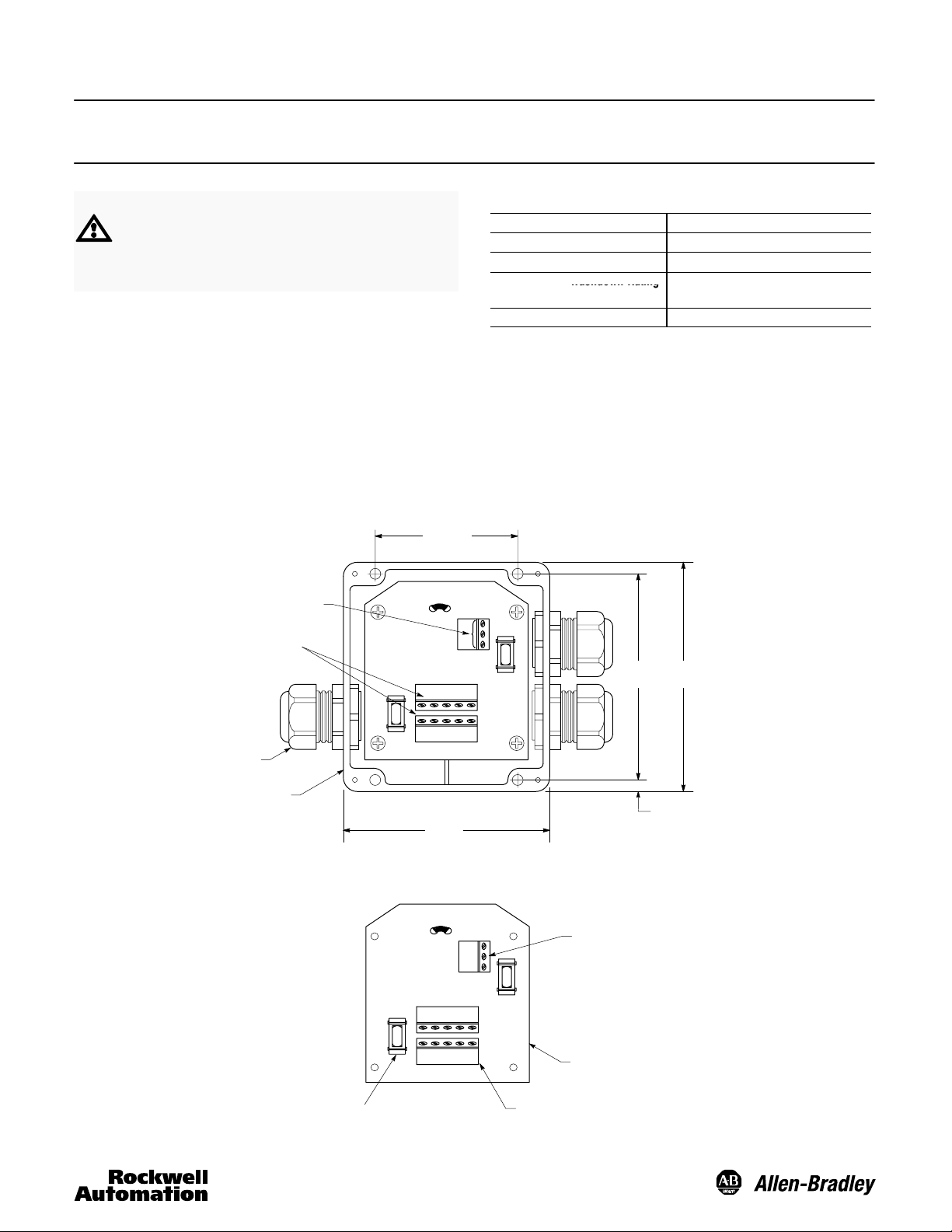
Figure 1: PowerTap Connection
Part Number: 1485T–P2T5–T5 and 1485T–P2T5–T5C
Dimensions—mm (inches)
67
(2.63)
DC Power Supply
Connection Terminals
Trunk Connection
Terminals
Specifications
Storage Temperature -40°C to +85°C (-40°F to 185°F)
Operating Temperature -25°C to +70°C max
Operating Humidity 5%-95% relative (noncondensing)
Washdown Rating
Housing Material Black polyester
Note: In class II applications the fuses are used as a means for
isolating network segments. For more information refer to DeviceNet
Cable Installation Guide.
(3.87)
1200 PSI (8270kPa) @ 60_C (140_F)
NEMA 3, 4x, 6P, 12 and 13
111.25
98
(4.38)
1485T-P2T5-T5-T5: Colors PG16 Cable Grips
1485T-P2T5-T5C-T5C: Colors PG9 Cable Grips
Enclosure
Figure 2: Wiring Diagram
Power Requirements: 24V DC 1% @
7.5 Amp Fast Blow Automotive Type
Fuse in each Trunk +24V DC Leg
(Littlefuse model 297 07.5 or similar)
Power Requirements: 24V DC 1% @
3.0 Amp Fast Blow Automotive Type
Fuse in each Trunk +24V DC Leg
(Littlefuse model 297 03 or similar)
1485T–P2T5–T5:
15.0 Amp (maximum)
1485T–P2T5–T5C:
6.0 Amp (maximum)
1485T-P2T5-T5 Mini Type Fuse, 7.5A Max.
1485T-P2T5-T5C Mini Type Fuse, 3.0A Max.
98.04
(3.86)
Black
Drain
Red
Black
Red
White
Blue
Drain
Drain
Blue
White
Black
Red
Terminal Block for
Power Supply Connection
PCB
Terminal Block for
Trunk Connections
6.6
(0.26)
Note: Red +24V
White CAN Hi
Blue CAN Lo
Black Common
Page 2
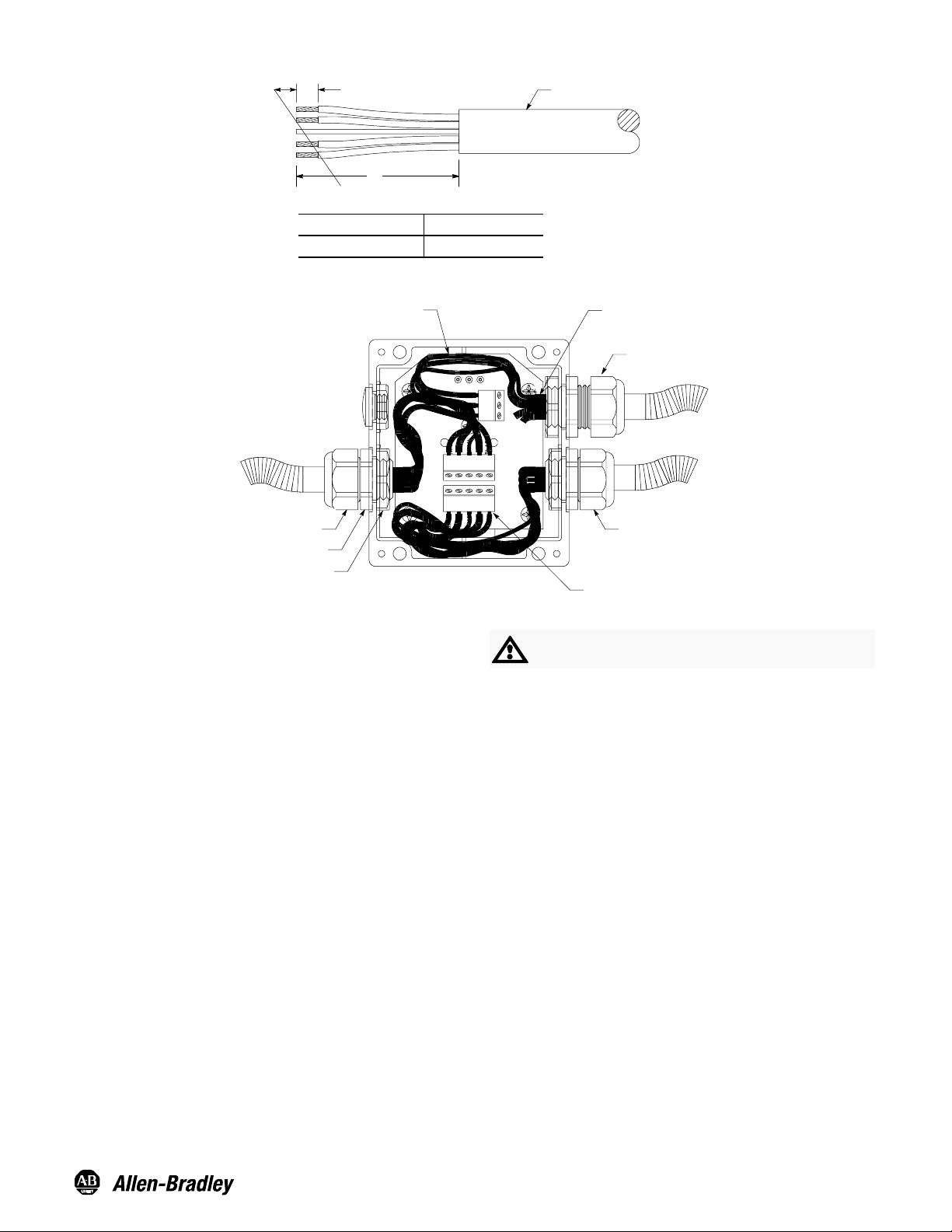
Figure 3: Cable Stripping Installation for PowerTap Connection
T
5/16
A
Dimension A"
runk Cable 4 inches
Figure 4:
Input from
Power Supply
Cable Jacket
End of Cable Jacket Should
Protrude Approx. 1/8 in.
Loosened
Gland Nut
Gland Nut
Hex Flange
Locking Nut
1. To install trunk cable into PowerTap connection cut and
strip gray PVC cable back approximately 4 inches (see
Figure 3) and insert through large cable gland. Note:
Trunk cable used for input from power supply should have
white and blue leads cut off short.
2. Loosen gland nut and insert cable until approximately 1/8
inch of cable jacket protrudes.
3. Firmly tighten gland nut to provide strain relief and sealing.
Caution: The hex flange must be held with the cable gland
wrench during tightening.
4. Bare wire ends should be firmly twisted to eliminate loose
strands and each lead looped approximately as shown, to
allow insertion into the clamping cavity of the terminal
block. (See Figure 2 for color codes.)
Tightened
Gland Nut
Align Wire End with Clamping
Cavity of Terminal Block
ATTENTION: Be certain to use insulating tubing
(included in accessory kit) on bare drain wire.
5. To attach cable to terminal strips, press down on cage
clamp, insert wire and release cage clamp. Repeat
process for remaining wires.
6. After all cables are terminated, the cover should be
installed and securely tightened to ensure washdown
rating.
All external wiring must conform to national electric code and
local codes.
Visit our web site at:
http://www.ab.com/sensors
Publication 75006–280–01(B)
September 2000
Printed in USA
 Loading...