

Page 1

User Manual
1442 Eddy Current Probe System
Page 2
Important User Information
IMPORTANT
Read this document and the documents listed in the additional resources section about installation, configuration, and
operation of this equipment before you install, configure, operate, or maintain this product. Users are required to
familiarize themselves with installation and wiring instructions in addition to requirements of all applicable codes, laws,
and standards.
Activities including installation, adjustments, putting into service, use, assembly, disassembly, and maintenance are required
to be carried out by suitably trained personnel in accordance with applicable code of practice.
If this equipment is used in a manner not specified by the manufacturer, the protection provided by the equipment may be
impaired.
In no event will Rockwell Automation, Inc. be responsible or liable for indirect or consequential damages resulting from the
use or application of this equipment.
The examples and diagrams in this manual are included solely for illustrative purposes. Because of the many variables and
requirements associated with any particular installation, Rockwell Automation, Inc. cannot assume responsibility or
liability for actual use based on the examples and diagrams.
No patent liability is assumed by Rockwell Automation, Inc. with respect to use of information, circuits, equipment, or
software described in this manual.
Reproduction of the contents of this manual, in whole or in part, without written permission of Rockwell Automation,
Inc., is prohibited.
Throughout this manual, when necessary, we use notes to make you aware of safety considerations.
WARNING: Identifies information about practices or circumstances that can cause an explosion in a hazardous environment,
which may lead to personal injury or death, property damage, or economic loss.
ATTENTION: Identifies information about practices or circumstances that can lead to personal injury or death, property
damage, or economic loss. Attentions help you identify a hazard, avoid a hazard, and recognize the consequence.
Identifies information that is critical for successful application and understanding of the product.
Labels may also be on or inside the equipment to provide specific precautions.
SHOCK HAZARD: Labels may be on or inside the equipment, for example, a drive or motor, to alert people that dangerous
voltage may be present.
BURN HAZARD: Labels may be on or inside the equipment, for example, a drive or motor, to alert people that surfaces may
reach dangerous temperatures.
ARC FLASH HAZARD: Labels may be on or inside the equipment, for example, a motor control center, to alert people to
potential Arc Flash. Arc Flash will cause severe injury or death. Wear proper Personal Protective Equipment (PPE). Follow ALL
Regulatory requirements for safe work practices and for Personal Protective Equipment (PPE).
Allen-Bradley, Rockwell Software, and Rockwell Automation are trademarks of Rockwell Automation, Inc.
Trademarks not belonging to Rockwell Automation are property of their respective companies.
Page 3

Summary of Changes
This manual contains new and updated information. Changes throughout this
revision are marked by change bars, as shown to the right of this paragraph.
New and Updated
Information
Temperature ranges and wire sizes were corrected as appropriate in this manual.
Top ic Pag e
Corrected temperature range 13, 17
Added Speed Measurements section and relocated speed measurement figure 16
Corrected wire size 37, 51
Rockwell Automation Publication ICM-UM004C-EN-E - February 2014 3
Page 4

Summary of Changes
Notes:
4 Rockwell Automation Publication ICM-UM004C-EN-E - February 2014
Page 5

Table of Contents
Preface
Installation
Measurement Principles . . . . . . . . . . . . . . . . . . . . . . . . . . . . . . . . . . . . . . . . . . . . 7
System Configuration Example. . . . . . . . . . . . . . . . . . . . . . . . . . . . . . . . . . . . . . 8
Additional Resources . . . . . . . . . . . . . . . . . . . . . . . . . . . . . . . . . . . . . . . . . . . . . . . 9
Chapter 1
Installation Environment . . . . . . . . . . . . . . . . . . . . . . . . . . . . . . . . . . . . . . . . . 12
Driver Installation Environment. . . . . . . . . . . . . . . . . . . . . . . . . . . . . . . 12
Sensor Installation Environment. . . . . . . . . . . . . . . . . . . . . . . . . . . . . . . 13
Extension Cable Installation Environment . . . . . . . . . . . . . . . . . . . . . 17
Outer Dimensions and Part Nomenclature. . . . . . . . . . . . . . . . . . . . . . . . . 17
1442 Sensor Outer Dimensions and Part Nomenclature . . . . . . . . . 17
Extension Cable Outer Dimensions and Part Nomenclature . . . . . 22
Driver Outer Dimensions and Part Nomenclature . . . . . . . . . . . . . . 24
Install the Driver. . . . . . . . . . . . . . . . . . . . . . . . . . . . . . . . . . . . . . . . . . . . . . . . . 25
Mount the Driver on the Housing or Panel . . . . . . . . . . . . . . . . . . . . . 25
Mount the Driver to a DIN Rail . . . . . . . . . . . . . . . . . . . . . . . . . . . . . . . 26
Install the Sensor. . . . . . . . . . . . . . . . . . . . . . . . . . . . . . . . . . . . . . . . . . . . . . . . . 26
Use a Sensor Mounting Bracket . . . . . . . . . . . . . . . . . . . . . . . . . . . . . . . 27
Use a Stinger . . . . . . . . . . . . . . . . . . . . . . . . . . . . . . . . . . . . . . . . . . . . . . . . . 28
Adjust the Gap . . . . . . . . . . . . . . . . . . . . . . . . . . . . . . . . . . . . . . . . . . . . . . . 30
Connect the Wiring. . . . . . . . . . . . . . . . . . . . . . . . . . . . . . . . . . . . . . . . . . . . . . 32
Connect the Extension Cable . . . . . . . . . . . . . . . . . . . . . . . . . . . . . . . . . 33
Connect the Sensor. . . . . . . . . . . . . . . . . . . . . . . . . . . . . . . . . . . . . . . . . . . 34
Connect the Module . . . . . . . . . . . . . . . . . . . . . . . . . . . . . . . . . . . . . . . . . 35
Verify the Connections . . . . . . . . . . . . . . . . . . . . . . . . . . . . . . . . . . . . . . . 35
Set Gap Voltage . . . . . . . . . . . . . . . . . . . . . . . . . . . . . . . . . . . . . . . . . . . . . . 35
Recommended Specifications for the Monitor Cable . . . . . . . . . . . . . . . . 37
Maintenance and Inspection
Individual Characteristic Data
Chapter 2
Periodic Inspection Intervals . . . . . . . . . . . . . . . . . . . . . . . . . . . . . . . . . . . . . . 39
Unit Life . . . . . . . . . . . . . . . . . . . . . . . . . . . . . . . . . . . . . . . . . . . . . . . . . . . . . . . . 39
Troubleshoot the Unit . . . . . . . . . . . . . . . . . . . . . . . . . . . . . . . . . . . . . . . . . . . 40
Chapter 3
Characteristic Data. . . . . . . . . . . . . . . . . . . . . . . . . . . . . . . . . . . . . . . . . . . . . . . 41
Standard Static Characteristics . . . . . . . . . . . . . . . . . . . . . . . . . . . . . . . . 41
Sensor Temperature Characteristics. . . . . . . . . . . . . . . . . . . . . . . . . . . . 42
Driver Temperature Characteristics. . . . . . . . . . . . . . . . . . . . . . . . . . . . 43
Static Characteristic Effect Due to Power Source Voltage Variation .
44
Static Characteristic Effect by Target Material . . . . . . . . . . . . . . . . . . 45
Static Characteristic Effect Due to Target Diameter. . . . . . . . . . . . . 46
Static Effect by Target Curved Surface . . . . . . . . . . . . . . . . . . . . . . . . . 47
Static Characteristic Effect Due to Target End Face . . . . . . . . . . . . . 48
Rockwell Automation Publication ICM-UM004C-EN-E - February 2014 5
Page 6

Table of Contents
Static Characteristic Effect Due to Side Wall. . . . . . . . . . . . . . . . . . . . 49
Frequency Characteristics . . . . . . . . . . . . . . . . . . . . . . . . . . . . . . . . . . . . . 50
Appendix A
Wire the Unit to a Monitor System
Index
Cable Wiring/Laying Examples. . . . . . . . . . . . . . . . . . . . . . . . . . . . . . . . . . . . 52
6 Rockwell Automation Publication ICM-UM004C-EN-E - February 2014
Page 7

Preface
This manual describes how to install and use the 1442 Series Eddy Current Probe
System.
The 1442 Series eddy current probe system performs non-contact measurement
of the distance between the sensor and the measured object (target), and outputs
a proportional voltage signal. The static component of the measurement is the
"gap," the absolute (DC) distance from the target surface to the probe tip. The
dynamic component of the measurement is the "vibration," the cyclical (AC)
movement of the target toward and away from the probe.
By combining this system with an Allen-Bradley® 1440 or 1444 Series
measurement module, you can measure the vibration of a rotating shaft, its
eccentricity, thrust position and rotating speed. The system is used for
continuous measurement or monitoring of shafts rotating at high speeds, such as
turbines, generators, and compressors.
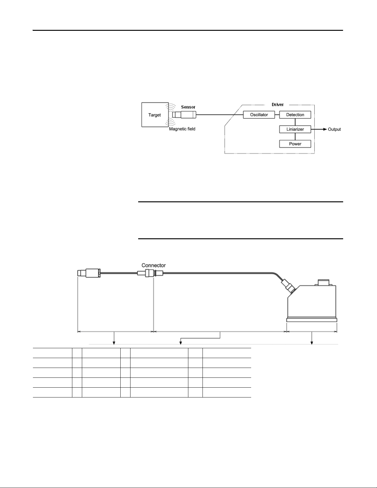
Measurement Principles
The gap between the sensor and the target is found according to the following
principles:
• When an approximately 1 MHz high frequency current is supplied from
the oscillator to the sensor, a high frequency magnetic field is created at the
sensor tip.
• The inter-linkage of the high frequency magnetic flux on the target
induces an eddy current that flows on the target surface.
• When the eddy current flows on the target surface, a magnetic field is
created at the target side, and the sensor impedance changes.
• When this change in output of the oscillator is detected, the distance
versus output voltage is made linear by a linearizer circuit, and the result is
output.
Rockwell Automation Publication ICM-UM004C-EN-E - February 2014 7
Page 8
Preface
IMPORTANT
You can find the gap between the sensor and the target by measuring the sensor
impedance if the following relationships are identified:
• Relationship between the sensor and the target gap.
• Relationship of the sensor impedance.
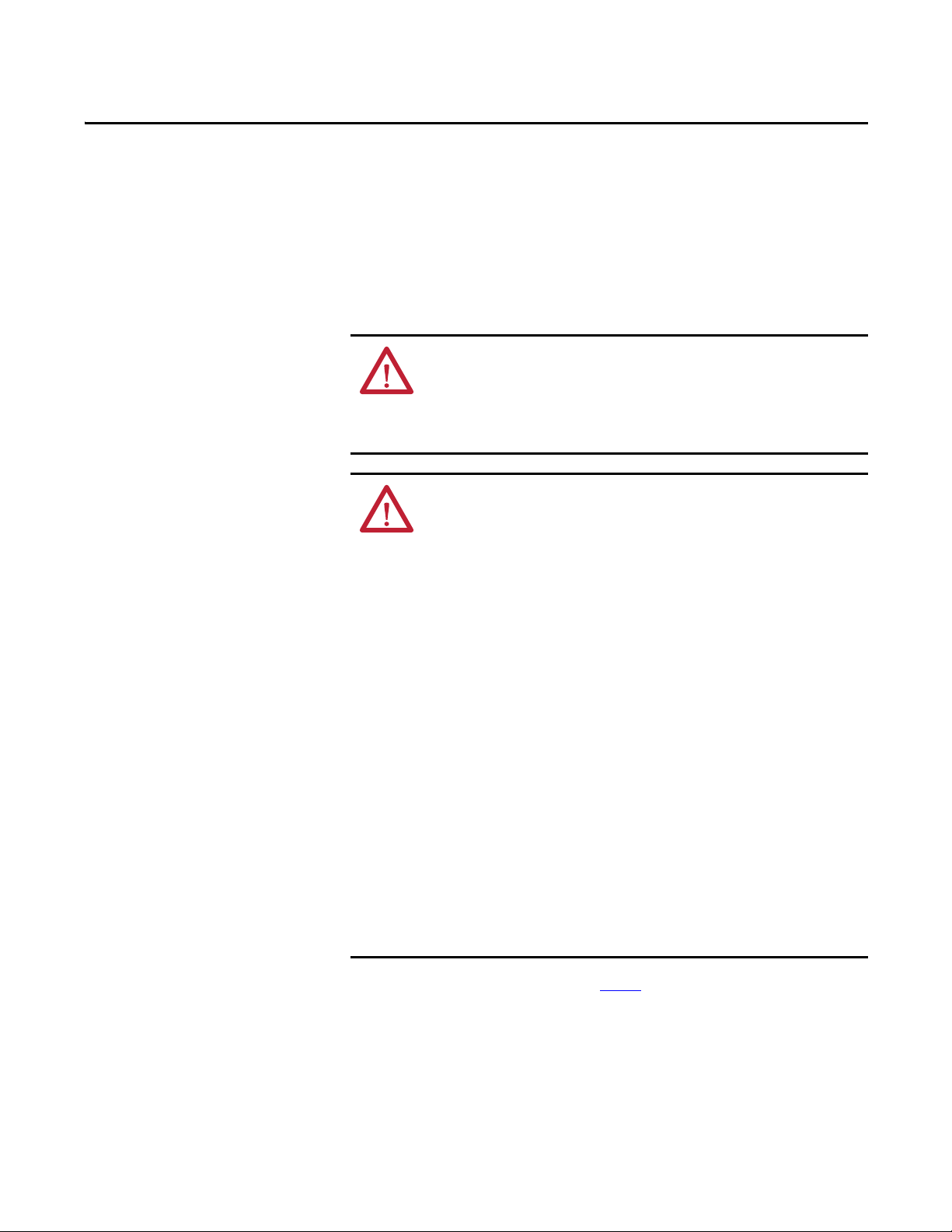
System Configuration Example
This system is designed to fulfill the specifications when used under the following
configuration.
Always combine the components of this system (sensor, extension cable,
and driver) to configure it as follows. If this system is not configured as
shown below, or if the 1442 extension cable is not used in combining the
1442 sensor and driver, the output characteristics will differ dramatically.
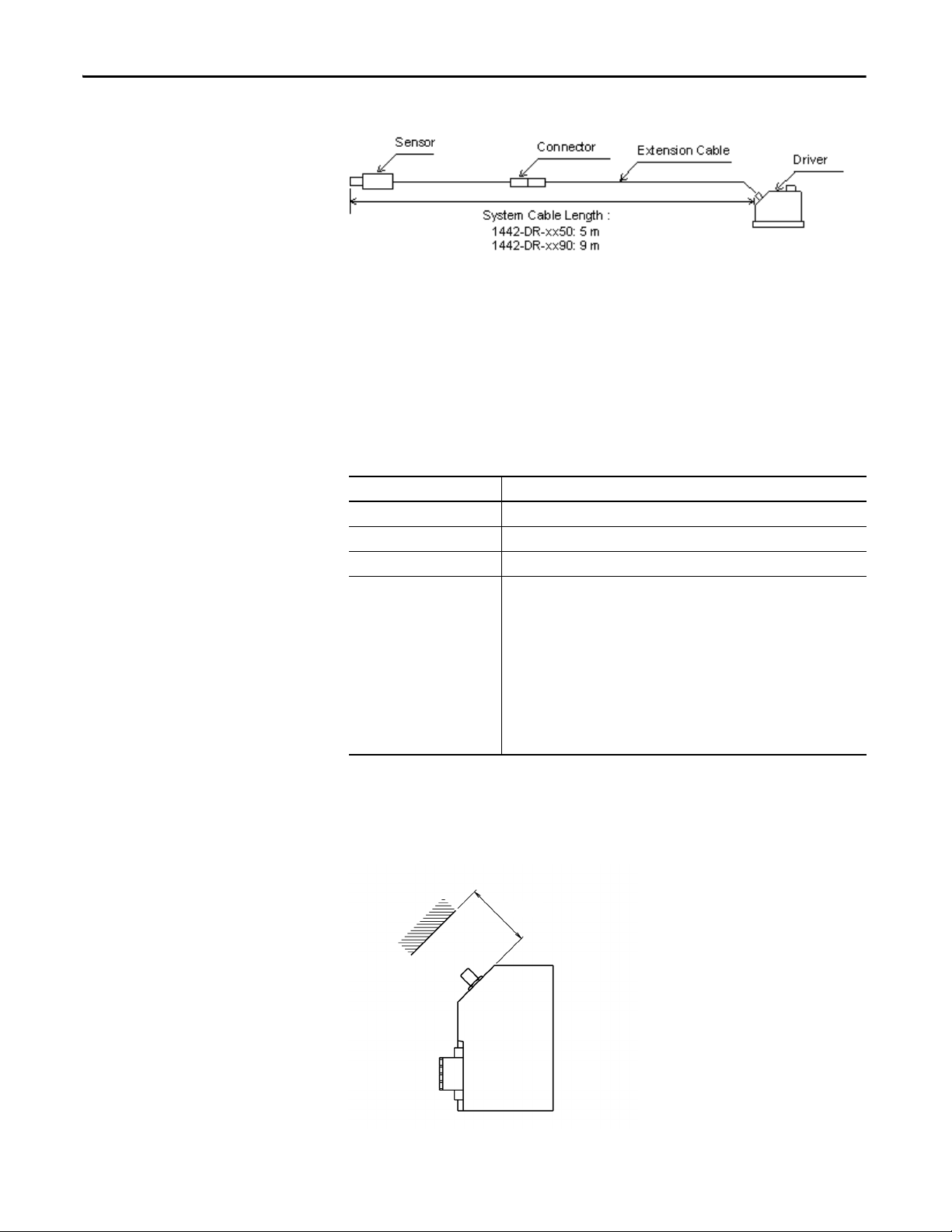
Figure 1 - System Configuration Example
Sensor Extension Cable System Cable Length Driver
0.5 m (1.64 ft) + 4.5 m (14.76 ft) = 5.0 m (16.40 ft) → 1442-DR-xx50
1.0 m (3.28 ft) + 4.0 m (13.12 ft) = 5.0 m (16.40 ft) → 1442-DR-xx50
0.5 m (1.64 ft) + 8.5 m (27.89 ft) = 9.0 m (29.53 ft) → 1442-DR-xx90
1.0 m (3.28 ft) + 8.0 m (26.25 ft) = 9.0 m (29.53 ft) → 1442-DR-xx90
(1)
(1) Where xx = appropriate code for probe size.
8 Rockwell Automation Publication ICM-UM004C-EN-E - February 2014
Page 9

Preface
Additional Resources
These documents contain additional information concerning related products
from Rockwell Automation.
Resource Description
1442 Eddy Current Probe Systems Specifications Technical Data, publication 1442-TD001. Provides specifications for the 1442 Eddy Current Probe System.
Turbine Supervisory Instrumentation System Selection Guide, publication GMSI10-
SG002.
Provides details to help you choose a Turbine Supervisory Instrumentation system.
You can view or download Rockwell Automation publications at http://
www.rockwellautomation.com/literature. To order paper copies of technical
documentation, contact your local Allen-Bradley distributor or Rockwell
Automation sales representative.
Rockwell Automation Publication ICM-UM004C-EN-E - February 2014 9
Page 10

Preface
Notes:
10 Rockwell Automation Publication ICM-UM004C-EN-E - February 2014
Page 11
Chapter 1
TIP
Installation
This chapter describes how to install a 1442 Series Eddy Current Probe System.
ATTENTION: Always ground the system. Never apply power until all
wiring work and connection work has been completed. If this is not
followed, there is a possibility of electrocution.
Installation work, wiring, and connections must be performed by a person
with knowledge in instrumentation.
ATTENTION: Be sure to adhere to the following guidelines:
• Before touching this unit, be sure to touch a metal section near by to
discharge any static electricity. The device can be damaged if exposed to
static electricity from a person’s body.
• Before applying power, make sure that all wiring is properly connected.
There is a possibility of damage to the unit and fire if improperly
connected.
• Install this unit away from motors and relays.
• Install the input/output signal cables away from power system and
control system cables. Noise occurring from the motor or relay can
adversely affect the measurement value. We recommend using separate
wiring ducts.
• Do not pull or bend the sensor cables and extension cables with
excessive force. The conductor in the cable can get cut off.
• The allowable tension of the sensor cables and extension cables is
98.1 N•m (10 kgf•m). The allowable bend radius is as follows:
– Without armored cable: 30 mm (1.18 in.)
– With armored cable: 50 mm (1.97 in.)
• After completing the installation, make sure all connections are correct
and tight before powering the system.
Refer to Appendix A on page 51 for recommended cable wiring, and
installation methods.
Rockwell Automation Publication ICM-UM004C-EN-E - February 2014 11
Page 12
Chapter 1 Installation
60 mm (2.4 in.)
Installation Environment
Driver Installation Environment
Install the driver in a location that satisfies the following environmental and
installation conditions.
Environmental Conditions
Feature Specification
Ambient temperature Must be in a range of -30…80 °C (-22…176 °F) when devices are operating.
Ambient humidity Must be in a range of 30…95% RH (noncondensing) when devices are operating.
Vibration condition Must be 10 m/s
Air cleanliness We recommend an air dust-particle amount of 0.2 mg/m3 or less.
We recommend an especially low amount of corrosive gasses, such as hydrogen
sulfide, NOx gas, and chlorine, and conductive particles, such as iron dust and
carbon. The allowable amounts of hydrogen sulfide and NOx gas, based on JEIDA29 (1979) Class S1, are shown below.
JEIDA: Japanese Electronic Industry Development Association
2
(1 g) or less at 10…150 Hz.
JEIDA-29 (1979) CLASS S1
Hydrogen sulfide: 0.01 ppm or less, NOx gas: 0.05 ppm or less
(Ambient temperature: 25 °C ± 5 °C (77 °F ± 9 °F), humidity: 40…80%
RH)
Install Conditions
• If there are walls or other obstacles at the cable connection surface of the
driver, make sure to keep spacing as illustrated below. Take care not to bend
the cable excessively.
12 Rockwell Automation Publication ICM-UM004C-EN-E - February 2014
Page 13
Installation Chapter 1
• Do not locate above heat emitting objects.
Sensor Installation Environment
Install the sensor at a location that satisfies the following environmental and
installation conditions.
Environmental Conditions
Feature Specification
Ambient temperature ATEX applications must be in a range of -35…80 °C (-31…176 °F) when devices
Ambient humidity Must be in a range of 30…95% RH (noncondensing) when devices are operating.
Vibrational conditions Must be 10 m/s
Air cleanliness We recommend an air dust-particle amount of 0.2 mg/m3 or less.
are operating.
CSA applications must be in a range of -35…85 °C (-31…185 °F) when devices
are operating.
Other applications must be in a range of -35…177 °C (-31…350 °F) when devices
are operating
2
measurement cannot be made.)
We recommend an especially low amount of corrosive gasses, such as hydrogen
sulfide, NOx gas, and chlorine, and conductive particles, such as iron dust and
carbon. The allowable amount sof hydrogen sulfide and NOx gas, based on JEIDA29 (1979) Class S1, are shown below.
JEIDA: Japanese Electronic Industry Development Association
(1 g) or less at 10…150 Hz. (If the sensor vibrates, an accurate
JEIDA-29 (1979) CLASS S1
Hydrogen sulfide: 0.01 ppm or less, NOx gas: 0.05 ppm or less
(Ambient temperature: 25 °C ± 5 °C (77 °F ± 9 °F), humidity: 40…80%
RH)
Installation Conditions
• Do not install at a location exposed to rain or other moisture. Moisture can
lead to reduced sensitivity of the sensor, and reduced insulation.
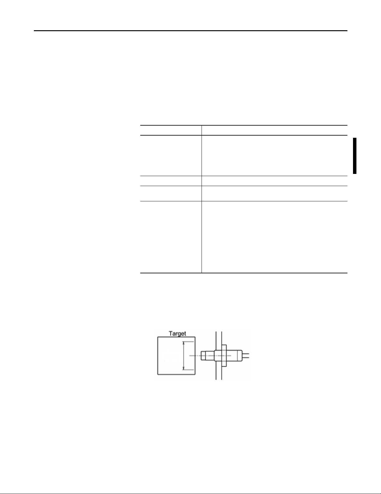
• A target surface area of not less than three times the tip diameter centered
on the sensor is required, as illustrated below.
Rockwell Automation Publication ICM-UM004C-EN-E - February 2014 13
Page 14
Chapter 1 Installation
40 mm (1.57 in.) or more
40 mm (1.57 in.) or more
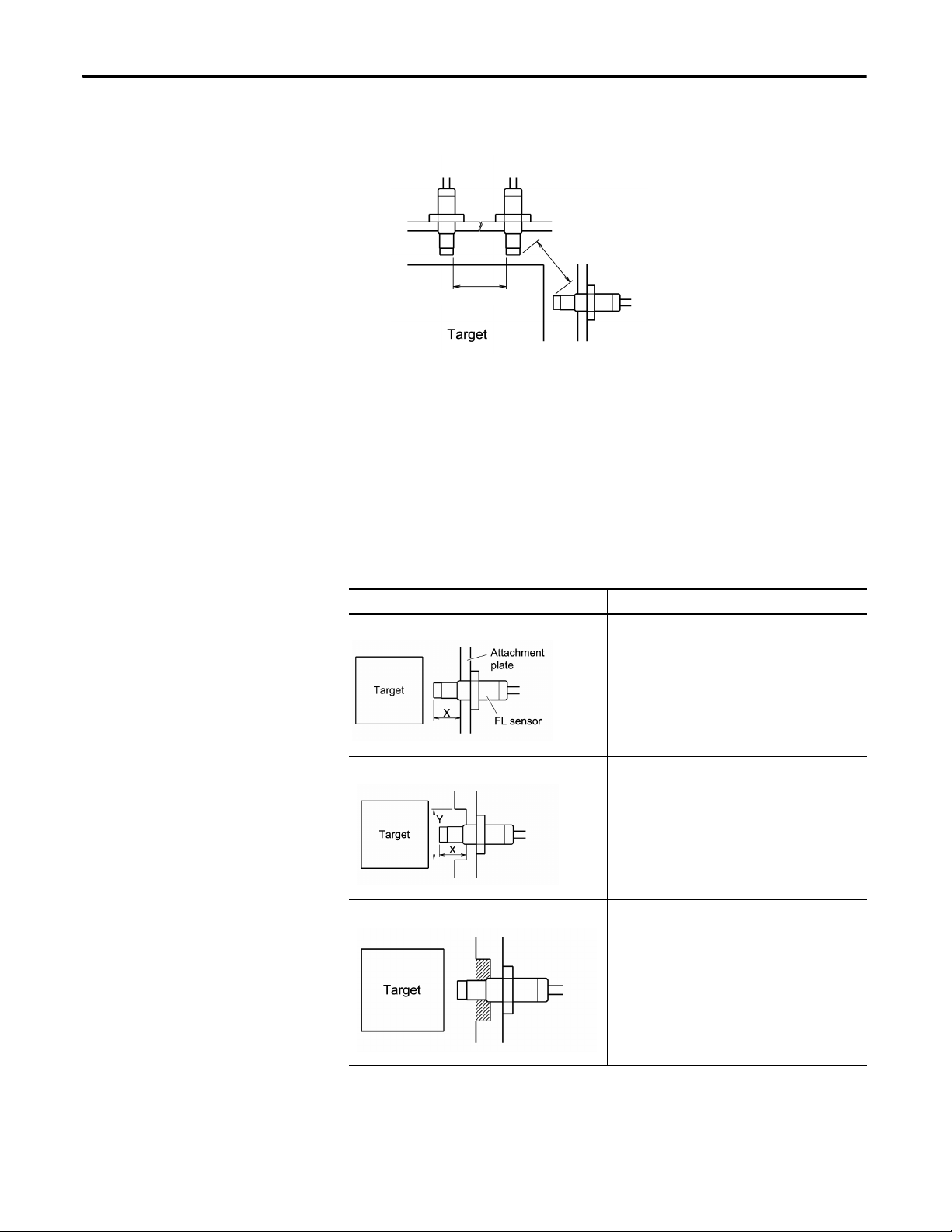
• When placing other sensors next to each other, separate the sensor tops by
not less than 10 times the sensor tip diameter to prevent interference.
• The sensor must be installed on a surface with adequate rigidity that is not
affected by an outside vibration. If the sensor vibrates, an accurate
measurement cannot be taken.
• For shapes and dimensions around the sensor, refer to the installation
examples (1…3) below. If a piece of metal other than the target is near the
sensor, an accurate reading cannot be taken.
If it is unavoidable to install the sensor as illustrated in examples 4…7,
check the characteristics at the attachment completed conditions.
Table 1 - Installation Examples
Example Description
Example 1 (most recommended) Dimension X is to be not less than 1.2 times the tip
Example 2 (recommended) Dimension X is to be not less than 1.2 times the tip
Example 3 (recommended) After constructing as shown in example 2, the area shown
diameter.
diameter
Dimension Y is to be not less than 3 times the tip
diameter.
by the shaded line in the illustration is filled with resin or
other insulating material.
14 Rockwell Automation Publication ICM-UM004C-EN-E - February 2014
Page 15
Installation Chapter 1
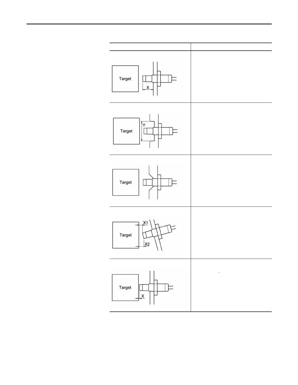
Table 1 - Installation Examples
Example Description
Example 4 If dimension X is less than 1.2 times the tip diameter, the
measurement will be affected by the attachment plate.
Example 5 If dimension Y is less than 3 times the tip diameter, the
Example 6 If the attachment plate around the sensor top is
Example 7 If the target and the sensor top are not parallel
measurement will be affected by the attachment plate.
chamfered, it will be affected by the attachment plate.
(dimension X1 and X2 are not the same), it will affect the
reading.
Example 8 If dimension X is less than the minimum linear range from
Rockwell Automation Publication ICM-UM004C-EN-E - February 2014 15
sensor tip specification for the sensor, the measurement
will not be accurate.
Page 16
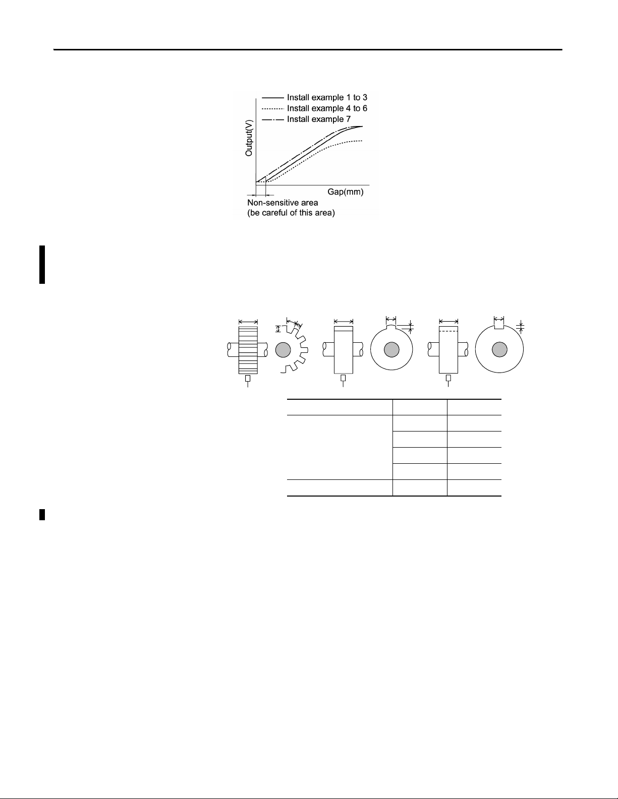
Chapter 1 Installation
The characteristics of output (V) and gap (mm) are as shown in the graph below.
Speed Measurements
Assumes measurements are made with a 5 mm or 8 mm probe.
Figure 2 - Dimension of target (recommended for rotational speed measurement):
D
B
A
C
D D
A
C
B
C
mm mils
Recommended dimension of
target (mm)
A ≥ 6A ≥ 236
B ≥ 7B ≥ 275
C ≥ 2.5 C ≥ 98
D ≥ 15 D ≥ 590
Recommended set gap (mm) 1.0...1.5 39...59
16 Rockwell Automation Publication ICM-UM004C-EN-E - February 2014
Page 17
Installation Chapter 1
Extension Cable Installation Environment
Install the extension cable in a location that satisfies the following environmental
and installation conditions.
Feature Specification
Ambient temperature Cable must be in a range of -35…177 °C (-31…350 °F) when devices are
Ambient humidity Must be in a range of 30…95% RH (noncondensing) when devices are operating.
operating.
Connector must be in a range of -35…125 °C
(-31…257 °F) when devices are operating.
ATEX applications must be in a range of -35…80 °C (-31…176 °F) when devices
are operating.
CSA applications must be in a range of -35…85 °C (-31…185 °F) when devices
are operating.
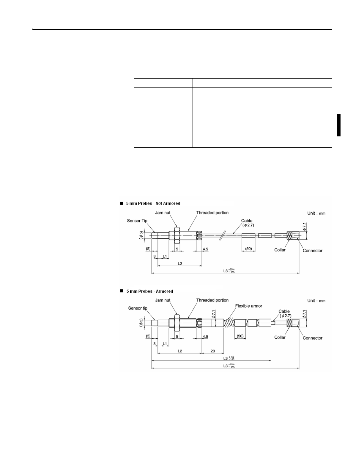
Outer Dimensions and Part Nomenclature
1442 Sensor Outer Dimensions and Part Nomenclature
5 mm Sensor
L1 = Unthreaded length
L2 = Case length
L3 = Cable length
Rockwell Automation Publication ICM-UM004C-EN-E - February 2014 17
Page 18

Chapter 1 Installation
8 mm Sensor
L1 = Unthreaded length
L2 = Case length
L3 = Cable length
Reverse 8 mm Sensor
L3 = Cable length
18 Rockwell Automation Publication ICM-UM004C-EN-E - February 2014
Page 19

11 mm Probes - Non Armored
L1 = Unthreaded length
L2 = Body length
L3 = Cable length
Installation Chapter 1
11 mm Probes - Armored
L1 = Unthreaded length
L2 = Body length
L3 = Cable length
Rockwell Automation Publication ICM-UM004C-EN-E - February 2014 19
Page 20

Chapter 1 Installation
18 mm Probes - Armored
L1 = Unthreaded length
L2 = Body length
L3 = Cable length
25 mm Probes - Armored
L1 = Unthreaded length
L2 = Body length
L3 = Cable length
20 Rockwell Automation Publication ICM-UM004C-EN-E - February 2014
Page 21

25 mm Probes - Flange Mount, Armored
2 = 4 holes in flange, 14 mm deep with M6 threads
L3 = Cable length, +30% / -0%
Installation Chapter 1
50 mm Probes - Armored
L2 = Body length
L3 = Cable length
Rockwell Automation Publication ICM-UM004C-EN-E - February 2014 21
Page 22

Chapter 1 Installation
Extension Cable Outer Dimensions and Part Nomenclature
5, 8, and 11 mm Probe Extension Cables - Non Armored
5 and 8 mm Probe Extension Cables - Armored
22 Rockwell Automation Publication ICM-UM004C-EN-E - February 2014
Page 23

11 mm to 50 mm Probe Extension Cables - Armored
Installation Chapter 1
Rockwell Automation Publication ICM-UM004C-EN-E - February 2014 23
Page 24

Chapter 1 Installation
Driver Outer Dimensions and Part Nomenclature
24 Rockwell Automation Publication ICM-UM004C-EN-E - February 2014
Page 25

Installation Chapter 1
TIP
Install the Driver
The driver can be installed on a DIN rail, or it can be mounted on a panel or wall
by using the provided adapter.
Mount the Driver on the Housing or Panel
The driver can be directly mounted on the panel.
When attaching to panels or mounts, make sure the surface is strong and
flat.
Attach the driver to the panel mounting plate and affix with the provided four
screws (M4 x 12 mm).
Terminal Arrangement
Ter mina l No. Sign al
1OUTPUT
2COM
3 -24 V
4Shield (COM)
Rockwell Automation Publication ICM-UM004C-EN-E - February 2014 25
Page 26

Chapter 1 Installation
TIP
TIP
Mount the Driver to a DIN Rail
The driver can be mounted to a 35 mm DIN rail.
1. Hook the upper tabs on the back of the driver onto the DIN rail.
2. Push the driver into the DIN rail until a click is heard from the slide lock.
Install the Sensor
If the driver does not fit onto the DIN rail well, pull on the slide lock and
push the driver against the DIN rail.
3. Make sure the upper tabs and the slide lock are securely fixed on the DIN
rail.
Remove the driver by pushing down on the slide lock with a flat-blade
screwdriver.
Install according to the conditions described in the Sensor Installation
Environment on page 13.
ATTENTION: Do not drop or otherwise subject the sensor to shock.
The sensor installation instructions comply with API Standard 670.
26 Rockwell Automation Publication ICM-UM004C-EN-E - February 2014
Page 27

Installation Chapter 1
Use a Sensor Mounting Bracket
If you need a mounting bracket for the sensor, construct your own mounting
bracket. The mounting bracket can be readily machined at your site. The bracket
must provide a stable, secure, platform that satisfies the conditions described in
the Sensor Installation Environment
When using a sensor mounting bracket, use the following steps to install the
sensor.
1. Attach the sensor mounting bracket to the mount (body), and temporarily
attach with bolts.
on page 13.
Insert the sensor into the sensor mounting brackets screw hole, and adjust
the gap between the sensor top face and the target.
Refer to
Set Gap Voltage on page 35.
2. Tighten the bolts further, and affix the sensor mounting bracket.
3. Retighten the lock nut gain at the specified torque.
Rockwell Automation Publication ICM-UM004C-EN-E - February 2014 27
Page 28

Chapter 1 Installation
TIP
Figure 3 - Sensor Mounting Bracket Installation Example
Use a Stinger
1442 Series 8-mm reverse-mount probes can be used with commonly available
probe holders. Stingers (also known as sensor sleeve), are provided with the probe
holder. Stingers can also be purchased from probe holder suppliers or can often
be machined locally.
The following instruction is a general guide based on common probe holder
designs. Consult your specific probe holder installation instructions for
additional details.
Install the probe holder and stinger assembly per installation instructions
before mounting the probe onto the stinger.
1. Remove the jam nut of the reverse mount sensor. (Remove at the Jam nut
attachment.)
28 Rockwell Automation Publication ICM-UM004C-EN-E - February 2014
Page 29

Installation Chapter 1
2. Attach the sensor to the sensor sleeve.
3. Attach the sensor sleeve to the mounting (machine casing).
4. Adjust the gap between the sensor top face and the target.
Figure 4 - Sensor Sleeve Installation Example
Rockwell Automation Publication ICM-UM004C-EN-E - February 2014 29
Page 30

Chapter 1 Installation
TIP
Adjust the Gap
Adjust the gap by using the following procedures.
After completing all wiring connections, you can perform gap adjustment
by using a tester.
Make sure to fully understand the content described in this chapter and
complete all connection work, then perform the gap adjustment by using
the Set Gap Voltage
procedures on page 35.
1. Refer to Standard Static Characteristics on page 41
, and prepare a gap gage
matching the gap to produce the desired characteristics.
Consider the following items for the gap:
• Set the gap so that even when the target is at the nearest point to the
sensor, the target does not come into direct contact with the sensor.
• Set the gap so that it does not go beyond the linear range of the
connection monitor.
2. Being careful not to scratch the sensor top and target surface, insert the gap
gage between the sensor top and target.
3. Adjust the sensor to a position where the gap gage just moves freely, and
affix in place with the jam nut.
4. Tighten the jam nut with the following torque.
Table 2 - Torque Requirements
Sensor Example
1442-PS-05xxM (5 mm metric) 1442-PS-0503M0010N 4 41 35.4
1442-PS-05xxE (5 mm English) 1442-PS-0512E0010N 1.4 15 12.4
1442-PS-08xxM (8 mm metric) 1442-PS-0803M0010N 8.5 87 75.2
1442-PS-08xxE (8 mm English) 1442-PS-0812E0010N 6.8 69 60.2
1442-PS-11xxM (11 mm metric) 1442-PS-1104M0510N 26.1 266 231
1442-PS-11xxE (11 mm English) 1442-PS-1116E0510N 18.6 190 164
1442-PS-18xxM (18 mm metric) 1442-PS-1805M0510A 58.8 600 520
30 Rockwell Automation Publication ICM-UM004C-EN-E - February 2014
Tightening Torque
N•m kgf-cm lb•in
Page 31

Table 2 - Torque Requirements
Tightening Torque
Sensor Example
1442-PS-18xxE (18 mm English) 1442-PS-1820E0510A 88.2 900 780
1442-PS-25xxM (25 mm metric) 1442-PS-2505M0510A 176 1800 1557
1442-PS-25xxE (25 mm English) 1442-PS-2520E0510A 196 2000 1734
1442-PS-50xxM (50 mm metric) 1442-PS-5005M0010A 176 1800 1557
1442-PS-50xxE (50 mm English) 1442-PS-5020E0010A 196 2000 1734
1442-PR-08xxM (8 mm rev mnt metric) 1442-PR-0803M0505N 8.5 87 75.2
1442-PR-08xxE (8 mm rev mnt English) 1442-PR-0812E0205N 6.8 69 60.2
N•m kgf-cm lb•in
ATTENTION: Make sure to tighten the jam nut at the specified torque.
If tightened with excessive torque, the sensor can be damaged. If the
tightening torque is too small, it can come loose.
Installation Chapter 1
Rockwell Automation Publication ICM-UM004C-EN-E - February 2014 31
Page 32

Chapter 1 Installation
TIP
TIP
Connect the Wiring
This section describes the wiring connections for the 1442 Series Eddy Current
Probe system.
The 1442 Series includes color–coded bands on the ends of each component.
The color–coded bands help you identify the length of the extension cable and
the length of the probe so that the total system length (5 or 9 meters) can be
matched to the appropriate driver. When the system is properly "sized," the color
bands for the probe, extension cable, and driver will match.
Table 3 - 1442 Series Color Band Table
Sensor Extension Cable Driver
Cable Length Color Band
Length
0.5 m Yellow 4.0 m Black Blue 5.0 Blue
1.0 m Black 4.5 Yellow Blue 9.0 Red
5.0 m Blue 8.0 Black Red
9.0 m Red 8.5 Yellow Red
Probe End Color
Band
Driver End Color
Band
System Cable
Length
Color
Band
WARNING: Make sure the wiring and connections are performed by a
person with knowledge in instrumentation.
WARNING: Make sure you ground your system. Never apply power until
all wiring and connection work has been completed. If this is not
followed there is a possibility of electrocution.
ATTENTION: Make sure to tighten the collar of the connector by hand.
Using a tool to tighten the collar can damage the connector. If the
installation environment does not allow proper tightening by hand and
there is a possibility that it can come loose, tighten an additional 1/4
turn using pliers after tightening by hand:
• Do not apply excessive force on the screws of the connector. The
connector can be damaged
• Do not cut the sensor or extension cables shorter. It can cause problems,
such as not being able to perform up to specifications.
Make sure that the cable is not twisted when connecting the connectors.
Twisting stress on the cable can slowly loosen the connection.
If a twisting force is applied to the direction where the collar is loosened,
twist the extension cable slightly to the opposite direction of the collar
tightening direction before connecting. Then connect the connector and
tighten the collar.
We recommend that excessive extension cables be stored in the cable
storage box. If it is unavoidable to store inside the driver housing, do not
force excessive cables into the housing.
32 Rockwell Automation Publication ICM-UM004C-EN-E - February 2014
Page 33

Installation Chapter 1
TIP
TIP
Connections are performed in the following order.
1. Connect the extension cable (when using the extension cable).
2. Connect the sensor.
3. Connect the XM® module.
4. Verify the connections.
5. Check the gap voltage.
Connect the Extension Cable
Use the following steps to connect the sensor and extension cable.
The connection area of the connector must not be exposed to water or oil. If
water or oil enters the connector, the cable capacity increases, and causes a
loss in sensitivity.
Make sure the color band on the sensor cable matches the color band on the
probe end of the extension cable. See
page 32.
1442 Series Color Band Table on
1. Confirm that there are no foreign objects in the sensor and extension cable
connectors.
Foreign objects in the connector cause faulty connections or faulty
characteristics.
2. Insert the extension cable through the provided insulation sleeve (clear
heat shrink tube).
3. Connect the sensor connector and extension cable connectors, and tighten
the collar by hand.
Rockwell Automation Publication ICM-UM004C-EN-E - February 2014 33
Page 34

Chapter 1 Installation
TIP
4. Cover the insulation sleeve over the connector.
5. Apply hot air on the insulation sleeve to shrink the insulation sleeve.
ATTENTION: Never use vinyl tape to insulate.
• During extended periods of use or when the connecter temperature
exceeds 80 °C (176 °F), vinyl electrical tape can harden or the adhesive
can deteriorate, leading to a dirty connector and faulty insulation.
• If there is not a spare insulation sleeve available, protect the connector
with a fluorine resin tape. Recommended insulation tape is:
– Manufacturer: Nitto Denko Corporation
– Product Name: Nitoflon adhesive tape (Model Number: NO. 903UL)
• Temperature spec: -60…180 °C (-76…356 °F) 0.08 mm thickness.
Connect the Sensor
Connect the sensor by using the following steps. Connection is performed in the
same manner when using an extension cable.
Make sure the color band on the extension cable matches the color band on
the probe driver. See
1. Confirm that there are no foreign objects in the sensor (or extension cable)
and in the driver sensor input connector.
2. Connect the sensor (or extension cable) connector and the sensor input
connector, and tighten the collar by hand.
1442 Series Color Band Table on page 32.
34 Rockwell Automation Publication ICM-UM004C-EN-E - February 2014
Page 35

Installation Chapter 1
Connect the Module
The 1442 sensors can be connected to many different Allen-Bradley 1440 XM
Series or 1444 Dynamix® Series modules. Refer to the appropriate Module User
Manual for wiring requirements and instructions on how to wire the sensor to the
module.
Verify the Connections
Before turning on the power, verify the following connections:
· Be sure that there are no loose terminals, and that all wiring is properly
connected.
· Check that the power line for the power source is connected to
NEGATIVE PWR (-24V) on the measurement module or its terminal
base.
· Be sure that the driver and sensor are installed at locations where the
installation environmental conditions are satisfied.
· Be sure that there are no problems with the driver and sensor installation,
and they are not installed at the following types of locations:
– Locations with high temperatures and high humidity.
– Locations with dust.
– Location exposed to vibration.
– Locations where there are metal objects, other than the target, near the
sensor.
After checking all items, check the set gap voltage values.
Set Gap Voltage
Perform confirmation of set gap voltage to maintain the performance of this unit
when doing the following:
• Supplying power to the unit for the first time
• More than one year has passed from the last confirmation
• The performance of this unit has been reduced due to a problem of some
sort
Follow these steps to check the set gap voltage.
1. Turn on th e p ow er.
2. Allow the unit to warm up for 5 minutes to stabilize the output.
Rockwell Automation Publication ICM-UM004C-EN-E - February 2014 35
Page 36

Chapter 1 Installation
IMPORTANT
Warm-up is necessary to collect accurate data.
3. Connect the tester (voltmeter) across the Input Signal and Input Common
terminals on the measurement module base and read the voltage.
4. Refer to Standard Static Characteristics on page 41
to make sure that the
desired set gap voltage is indicate
Data indicated in Standard Static Characteristics (on page 41) are measured
for a SCM440 flat target (diameter more than 33 mm). When the target
material or shapes differ, the output characteristics (gain) differ, making it
necessary to compensate with later equipment.
5. If the desired set gap voltage is not attained, readjust the sensor position by
using the following procedure.
a. Loosen the sensor jam nut.
b. Adjust the sensor position so that the desired set gap voltage is
attained.
36 Rockwell Automation Publication ICM-UM004C-EN-E - February 2014
Page 37

Installation Chapter 1
TIP
c. After adjustment, tighten the sensor jam nut to the specified torque
value (see table on page 30
).
ATTENTION: Always tighten the lock nut at the specified torque.
The measurement precision described in the specifications will be satisfied
approximately five minutes after turning on the power.
Recommended Specifications for the Monitor Cable
Cable Name Note
CVVS 3 core shielded cable (straight) The CVVS 3 core shield is also recommended in the API Standard 670.
3 line multiple core cable for light elec trical instruments
(individually shielded)
Use a commercially sold cable to connect the probe driver to the monitor. A
CVVS 3 core shielded cable (straight) is recommended, but if it is not available, a
3 line multiple core cable for light electrical instruments (individually shielded)
can be used. Use 0.75 mm
2
…1.25 mm2 (18…16 AWG) cables.
Recommendation: Copper tape shield (core wire; soft copper wire); (Normally,
silver plated braid)
Use conduit pipe (cable rack) for wiring.
Recommendation: Outer shield is aluminum tape, copper tape shield
The multipair cable can contain a mixture of vibration signals and displacement
signals. However, vibration signals for a high amplitude vibration can affect other
vibration signals and displacement signals negatively; and these need to be
wired on a separate cable.
Rockwell Automation Publication ICM-UM004C-EN-E - February 2014 37
Page 38

Chapter 1 Installation
Notes:
38 Rockwell Automation Publication ICM-UM004C-EN-E - February 2014
Page 39

Chapter 2
IMPORTANT
Calibration
(Static characteristic data collection)
The margin for error satisfies the specifications.
(Thrust, Rotations --> sensitivity)
(Vibration, Eccentric --> scale factor)
Verify the installation, reset the gap and/or troubleshoot
the system per this instruction.
Does the system performance satisfy the specifications?
Replacement is recommended.
Continue to use the unit.
Continue to use the unit after adjustment.
Ye s
Ye s
No
No
Maintenance and Inspection
This chapter describes the maintenance and inspection procedures for the unit.
Periodic Inspection Intervals
Unit Life
To maintain performance and secure system stability of the unit, inspect the
system and its mounts for corrosion, properly-tightened or torqued fittings and
connections, and component conditions annually. Check sensor gap settings
annually and at any time measurements become suspect. Refer to Set Gap Voltage
on page 36.
Plan to replace eddy current probe systems approximately every 10 years.
Ten years is a general guideline for replacement. If otherwise undisturbed,
eddy current probe systems deteriorate over time due to temperature and
erosion. The deterioration rate for sensors, extension cables, and drivers
depends on the specific environmental conditions to which each
component is subjected.
The following is a flowchart for determining when a replacement is required.
Rockwell Automation Publication ICM-UM004C-EN-E - February 2014 39
Page 40

Chapter 2 Maintenance and Inspection
Troubleshoot the Unit
Symptom Possible Cause Recommended Action
Output is 0V DC and does not change. Power is not on. Turn on the power.
Output is approximately -0.7V DC and does not change. The target is beyond the measurement range. Refer to Set Gap Voltage on page 36 to adjust the gap.
Output is approximately -22V DC and does not change. The target is outside the possible measurement range. Refer to Set Gap Voltage on page 36
Use the table below to troubleshoot problems with the unit.
Unit is not connected properly. Refer to Connect the Wiring on page 32
The driver is faulty. Replace the driver.
The sensor failed or the sensor cable is shorted or
disconnected.
The extension cable is shorted or disconnected. Measure the resistance of the extension cable, and if it is
There is a foreign object in the connector. Disconnect the connector, and remove foreign object in
The driver is faulty. Replace the driver.
The driver is faulty. Replace the driver.
unit is wired correctly.
Measure the resistance between the sensor connector,
and if not normal, replace the sensor.
Normal value:
Sensor coil resistance: Approx. 5.5 Ω
Sensor cable resistance: Approx. 0.25 Ω/m
not normal, replace the extension cable.
Normal value:
Center conductor resistance: Approx. 0.25 Ω/m
Outer conduc tor resistance: 0 Ω
Center pin to outer conductor resistan ce: ∞Ω
the connector.
to make sure the
to adjust the gap.
40 Rockwell Automation Publication ICM-UM004C-EN-E - February 2014
Page 41

Individual Characteristic Data
Chapter 3
Characteristic Data
This chapter describes static characteristics, temperature characteristics, and
other characteristic data. Use this data to determine the gap.
Standard Static Characteristics
Target material is SCM440 flat face (diameter 15 mm or more).
Rockwell Automation Publication ICM-UM004C-EN-E - February 2014 41
Page 42

Chapter 3 Individual Characteristic Data
Sensor Temperature Characteristics
System cable length is 5 m.
42 Rockwell Automation Publication ICM-UM004C-EN-E - February 2014
Page 43

Driver Temperature Characteristics
System cable length is 5 m.
Individual Characteristic Data Chapter 3
Rockwell Automation Publication ICM-UM004C-EN-E - February 2014 43
Page 44

Chapter 3 Individual Characteristic Data
Static Characteristic Effect Due to Power Source Voltage Variation
44 Rockwell Automation Publication ICM-UM004C-EN-E - February 2014
Page 45

Individual Characteristic Data Chapter 3
Static Characteristic Effect by Target Material
Rockwell Automation Publication ICM-UM004C-EN-E - February 2014 45
Page 46

Chapter 3 Individual Characteristic Data
Static Characteristic Effect Due to Target Diameter
Target material is SCM440.
46 Rockwell Automation Publication ICM-UM004C-EN-E - February 2014
Page 47

Static Effect by Target Curved Surface
Target material is SCM440.
Individual Characteristic Data Chapter 3
Rockwell Automation Publication ICM-UM004C-EN-E - February 2014 47
Page 48

Chapter 3 Individual Characteristic Data
Static Characteristic Effect Due to Target End Face
Target material is SCM440.
48 Rockwell Automation Publication ICM-UM004C-EN-E - February 2014
Page 49

Static Characteristic Effect Due to Side Wall
Target and side wall material is SCM440.
Individual Characteristic Data Chapter 3
Rockwell Automation Publication ICM-UM004C-EN-E - February 2014 49
Page 50

Chapter 3 Individual Characteristic Data
Frequency Characteristics
50 Rockwell Automation Publication ICM-UM004C-EN-E - February 2014
Page 51

Appendix A
Wire the Unit to a Monitor System
The 1442 Series Probe System is designed to satisfy the API-670 standard. Any
monitor designed to connect API-670 probes can be used with these sensors.
Consider the following recommendations when wiring the probe driver to a
monitor:
· Use a good quality instrumentation cable with three-conductor stranded
wire and shield.
– Wire must be rated with a maximum capacitance of 60 pF/ft
(197 pF/m) and inductance of 0.3 µH/ft (1 µH/m).
– Use wire with insulation suitable for the environment and with
adequate tensile strength and flexibility for the application.
– Use wire with a foil shield for use in environments where radio
frequency interference (RFI) may be present. Use a wire with a braid
shield for environments where electromagnetic interference (EMI) may
be present.
– Use 0.75…1.25 mm (18…16 AWG) gauge wire.
· Make sure the wire is isolated from power cables and any other wiring that
may be transmitting high-voltage power or control signals.
· Any cable transmitting pulse-type vibration signals such as a phase marker
or speed pulse must be isolated from displacement and vibration signals.
· Run wire within conduit and cable trays and as per any local electrical
codes.
· Do not exceed a wire length of 500 m (546.81 yds). However, limiting the
length to 300 m (328.08 yds) transmits vibration signals in the 0…10 kHz
frequency range with minimal attenuation. When longer lengths are
needed the capacitance of the cable and the desired frequency response of
the system must be considered.
· In most cases, ground the cable shield at only one point, generally at the
monitor.
Rockwell Automation Publication ICM-UM004C-EN-E - February 2014 51
Page 52

Appendix A Wire the Unit to a Monitor System
Cable Wiring/Laying Examples
Good Example Bad Example
The following illustrations provide examples on how to wire and lay the cable.
52 Rockwell Automation Publication ICM-UM004C-EN-E - February 2014
Page 53

Index
Numerics
1442 driver
dimensions
installation
installation environment
1442 extension cable
connecting
dimensions
1442 reverse mount probe
dimensions
1442 Sensors
connecting
dimensions
installation environment
24
25
12
33
22
18, 19, 20, 21
34
17
13
C
cable wiring 51
examples
51
issues
characteristic data 41
51
D
dimensions 17
din rail mounting
driver installation
din rail mounting
housing mounting
panel mounting 25
driver installation environment
26
25
26
25
12
P
panel mounting 25
S
sensor installation 26
gap adjustment
mounting bracket
stinger 28
sensor installation environment
set gap voltage
specifications
monitor cable
Stingers
28
system configuration example
30
27
35
37
T
troubleshooting 40
W
wiring connections 32
extension cable
sensor
set gap voltage 35
verification
XM module
wiring recommendations 51
33
34
35
35
13
8
G
gap adjustment 30
H
housing mounting 25
I
installation
driver
25
sensor
26
installation environment
driver
12
13
sensor
introduction
7
12
M
maintenance and inspection 39
measuring principles
mounting bracket
7
27
Rockwell Automation Publication ICM-UM004C-EN-E - February 2014 53
Page 54

Index
54 Rockwell Automation Publication ICM-UM004C-EN-E - February 2014
Page 55

Page 56

Rockwell Automation Support
Rockwell Otomasyon Ticaret A.Ş., Kar Plaza İş Merkezi E Blok Kat:6 34752 İçerenköy, İstanbul, Tel: +90 (216) 5698400
Rockwell Automation provides technical information on the Web to assist you in using its products.
At http://www.rockwellautomation.com/support
software service packs. You can also visit our Support Center at https://rockwellautomation.custhelp.com/
updates, support chats and forums, technical information, FAQs, and to sign up for product notification updates.
In addition, we offer multiple support programs for installation, configuration, and troubleshooting. For more
information, contact your local distributor or Rockwell Automation representative, or visit
http://www.rockwellautomation.com/services/online-phone
Installation Assistance
If you experience a problem within the first 24 hours of installation, review the information that is contained in this
manual. You can contact Customer Support for initial help in getting your product up and running.
United States or Canada 1.440.646.3434
Outside United States or Canada Use the Wor ldwi de Lo cato r
Rockwell Automation representative.
at http://www.rockwellautomation.com/rockwellautomation/support/overview.page, or contact your local
New Product Satisfaction Return
you can find technical and application notes, sample code, and links to
for software
.
Rockwell Automation tests all of its products to help ensure that they are fully operational when shipped from the
manufacturing facility. However, if your product is not functioning and needs to be returned, follow these procedures.
United States Contact your distributor. You must provide a Customer Support case number (call the phone number above to obtain one) to your
Outside United States Please contact your local Rockwell Automation representative for the return procedure.
distributor to complete the return process.
Documentation Feedback
Your comments will help us serve your documentation needs better. If you have any suggestions on how to improve this
document, complete this form, publication RA-DU002
, available at http://www.rockwellautomation.com/literature/.
Publication ICM-UM004C-EN-E - February 2014
Supersedes Publication ICM-UM004B-EN-E - April 2013 Copyright © 2014 Rockwell Auto mation, Inc. All rights reserved. Pr inted in the U.S.A.
 Loading...