

Page 1

User Manual
Balancing Extension Module for the Dynamix 2500
Data Collector
Catalog Number
1441-DYN25-MBAL
Page 2
Important User Information
IMPORTANT
Solid-state equipment has operational characteristics differing from those of electromechanical equipment. Safety
Guidelines for the Application, Installation and Maintenance of Solid State Controls (publication SGI-1.1
your local Rockwell Automation sales office or online at http://www.rockwellautomation.com/literature/
important differences between solid-state equipment and hard-wired electromechanical devices. Because of this difference,
and also because of the wide variety of uses for solid-state equipment, all persons responsible for applying this equipment
must satisfy themselves that each intended application of this equipment is acceptable.
In no event will Rockwell Automation, Inc. be responsible or liable for indirect or consequential damages resulting from
the use or application of this equipment.
The examples and diagrams in this manual are included solely for illustrative purposes. Because of the many variables and
requirements associated with any particular installation, Rockwell Automation, Inc. cannot assume responsibility or
liability for actual use based on the examples and diagrams.
No patent liability is assumed by Rockwell Automation, Inc. with respect to use of information, circuits, equipment, or
software described in this manual.
Reproduction of the contents of this manual, in whole or in part, without written permission of Rockwell Automation,
Inc., is prohibited.
Throughout this manual, when necessary, we use notes to make you aware of safety considerations.
WARNING: Identifies information about practices or circumstances that can cause an explosion in a hazardous
environment, which may lead to personal injury or death, property damage, or economic loss.
available from
) describes some
ATTENTION: Identifies information about practices or circumstances that can lead to personal injury or death,
property damage, or economic loss. Attentions help you identify a hazard, avoid a hazard, and recognize the
consequence
SHOCK HAZARD: Labels may be on or inside the equipment, for example, a drive or motor, to alert people that
dangerous voltage may be present.
BURN HAZARD: Labels may be on or inside the equipment, for example, a drive or motor, to alert people that
surfaces may reach dangerous temperatures.
Identifies information that is critical for successful application and understanding of the product.
Allen-Bradley, Rockwell Software, Rockwell Automation, Dynamix, Enpac, Emonitor, and TechConnect are trademarks of Rockwell Automation, Inc.
Trademarks not belonging to Rockwell Automation are property of their respective companies.
Page 3

Table of Contents
Preface
Installing Optional Extension
Modules
Balancing Extension Module
Index
Optional Extension Modules. . . . . . . . . . . . . . . . . . . . . . . . . . . . . . . . . . . . . . . . 5
Additional Resources . . . . . . . . . . . . . . . . . . . . . . . . . . . . . . . . . . . . . . . . . . . . . . . 6
Chapter 1
Install Extension Modules . . . . . . . . . . . . . . . . . . . . . . . . . . . . . . . . . . . . . . . . . . 7
Uninstall Extension Modules. . . . . . . . . . . . . . . . . . . . . . . . . . . . . . . . . . . . . . . . 9
Manage Extension Modules . . . . . . . . . . . . . . . . . . . . . . . . . . . . . . . . . . . . . . . 12
Extension Module Battery Status Indicators . . . . . . . . . . . . . . . . . . . . . . . . 13
Chapter 2
Balancing Measurements. . . . . . . . . . . . . . . . . . . . . . . . . . . . . . . . . . . . . . . . . . 16
Plane Balancing . . . . . . . . . . . . . . . . . . . . . . . . . . . . . . . . . . . . . . . . . . . . . . . . . . 16
Static-couple Balancing . . . . . . . . . . . . . . . . . . . . . . . . . . . . . . . . . . . . . . . . . . . 18
Set Up the Balancing Parameters . . . . . . . . . . . . . . . . . . . . . . . . . . . . . . . . . . 20
Balance Setup Screen . . . . . . . . . . . . . . . . . . . . . . . . . . . . . . . . . . . . . . . . . 21
Single Plane Balancing . . . . . . . . . . . . . . . . . . . . . . . . . . . . . . . . . . . . . . . . . . . . 26
Single Plane Balancing Procedure Overview. . . . . . . . . . . . . . . . . . . . . 26
Take the Initial Vibration Measurement. . . . . . . . . . . . . . . . . . . . . . . . 27
Add the Trial Weight. . . . . . . . . . . . . . . . . . . . . . . . . . . . . . . . . . . . . . . . . 28
Enter the Trial Weight Manually . . . . . . . . . . . . . . . . . . . . . . . . . . . . . . 29
Estimate the Trial Weight. . . . . . . . . . . . . . . . . . . . . . . . . . . . . . . . . . . . . 30
Take a Trial Run Weight Measurement . . . . . . . . . . . . . . . . . . . . . . . . 32
Take a Correction Run . . . . . . . . . . . . . . . . . . . . . . . . . . . . . . . . . . . . . . . 35
Perform a Trim Run . . . . . . . . . . . . . . . . . . . . . . . . . . . . . . . . . . . . . . . . . . 37
Add the Correction Weight and Take a Residual Measurement . . 41
Two Plane Balancing . . . . . . . . . . . . . . . . . . . . . . . . . . . . . . . . . . . . . . . . . . . . . 45
Two Plane Balancing Procedure Overview. . . . . . . . . . . . . . . . . . . . . . 46
How to Set Up a Two-Plane Procedure . . . . . . . . . . . . . . . . . . . . . . . . 46
How to Perform Two-plane Balancing . . . . . . . . . . . . . . . . . . . . . . . . . 50
Move Around in a Balance Run. . . . . . . . . . . . . . . . . . . . . . . . . . . . . . . . 60
Saving, Loading, and Reviewing Balance Measurements . . . . . . . . . . . . . 61
Save a Balance Measurement . . . . . . . . . . . . . . . . . . . . . . . . . . . . . . . . . . 61
Load a Previously Saved Setup . . . . . . . . . . . . . . . . . . . . . . . . . . . . . . . . . 62
Review Balancing Measurements. . . . . . . . . . . . . . . . . . . . . . . . . . . . . . . 63
How to Delete Stored Files. . . . . . . . . . . . . . . . . . . . . . . . . . . . . . . . . . . . 64
Rockwell Automation Publication 1441-UM004A-EN-P - May 2011 3
Page 4

Table of Contents
Notes:
4 Rockwell Automation Publication 1441-UM004A-EN-P - May 2011
Page 5

Preface
This manual describes the Balancing extension module for the Dynamix 2500
data collector. You install the extension module with the Balancing Secure Digital
(SD) card.
Optional Extension
Modules
See Installing Optional Extension Modules on page 7
instructions.
The balancing test determines the amount and location of the heavy spot on a
rotating shaft so that you can balance it with an equal amount of weight in the
opposite direction.
There are three types of measurements in the balancing process:
• Initial Vibration
• Tri al Wei gh t
• Residual Measurements
These are the optional extension modules for the Dynamix 2500 data collector:
• 1441-DYN25-4C, 4-channel Activation
The 4-channel activation lets you take 3- and 4-channel magnitude, time
waveform, spectra, and Offroute measurements.
• 1441-DYN25-MBMP Bump Test
A bump test (or hammer test) determines the natural frequencies of a
machine or a structure.
• 1441-DYN25-MBAL Balancing
for installation
(1)
Balancing application resolves single-plane, two-plane, and static-couple
balances with high precision.
• 1441-DYN25-MFRF Frequency Response Function
The FRF test lets you determine the natural frequencies of a machine as
well as sophisticated information about the frequency response of the
structure being tested.
• 1441-DYN25-MREC Time Recorder
The Time Recorder test uses a the instrument as a data recorder for real-
time data acquisition and analysis.
• 1441-DYN25-MRUC Run Up Coast Down
The RUCD test records and analyzes data from intermittent events and
transient vibration signals from non-steady state machines.
See Additional Resources on page 6
(1) This is an activation license for the Dynamix 2500 data collector.
Rockwell Automation Publication 1441-UM004A-EN-P - May 2011 5
for a listing of available publications.
Page 6
Preface
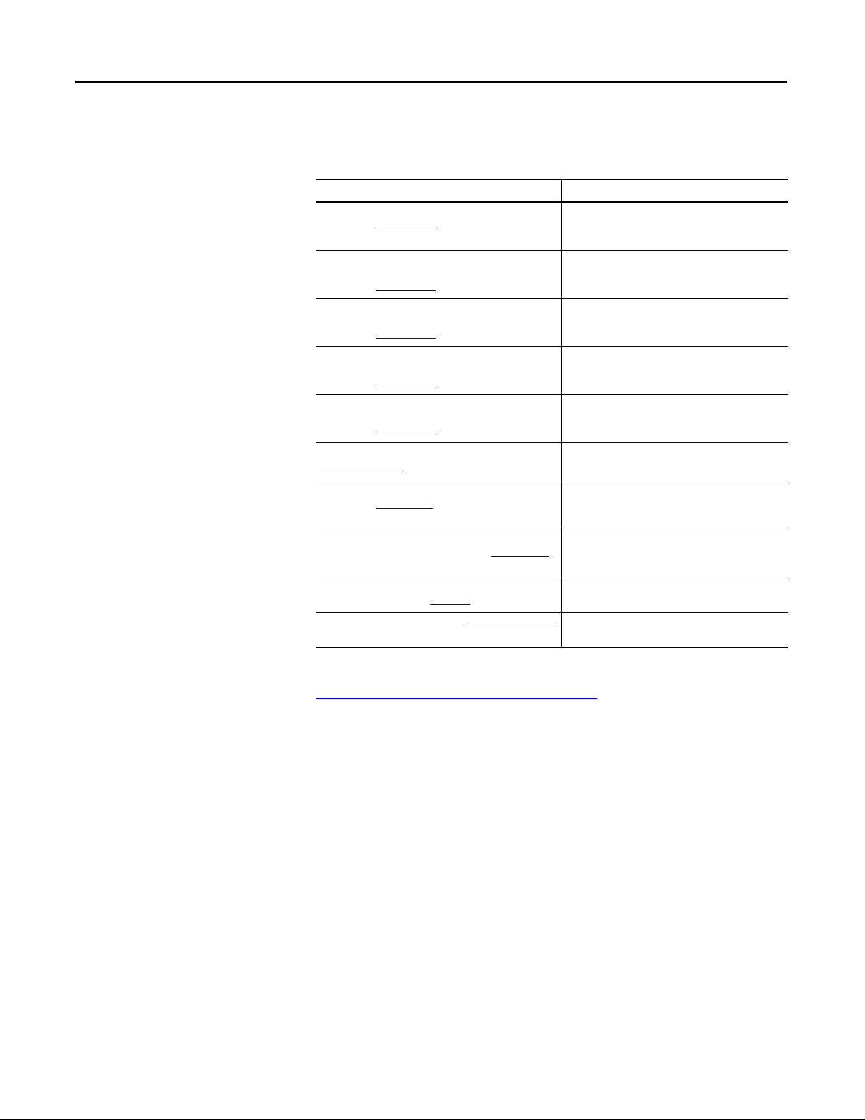
Additional Resources
These documents contain additional information concerning related products
from Rockwell Automation.
Resource Description
Dynamix 2500 Data Collector User Manual,
publication 1441-UM001
Bump Test Extension Module for the Dynamix 2500
Data Collector User Manual,
publication 1441-UM002
Frequency Response Function Extension Module
for the Dynamix 2500 Data Collector User Manual,
publication 1441-UM003
Time Recorder Extension Module for the Dynamix
2500 Data Collector User Manual,
publication 1441-UM005
Run Up Coast Down Extension Module for the
Dynamix 2500 Data Collector User Manual,
publication 1441-UM006
Emonitor User’s Guide, publication
EMONTR-UM001
Dynamix 2500 Data Collector Kit Release Notes,
publication 1441-RN001
Dynamix 2500 Data Collector Optional Extension
Modules Release Notes, publication 1441-RN002
Industrial Automation Wiring and Grounding
Guidelines, publication 1770-4.1
Product Certifications website, http://www.ab.com
Describes the Dynamix 2500 data collector
which provides predictive maintenance by
using noise and vibration analysis.
Describes how determine natural (or resonant)
frequencies of a machine or structure.
Describes how to determine the natural
frequencies of a machine or structure by using
modal hammer.
Describes how to use the data collector as a
data recorder for real-time data acquisition,
post processing, and analysis.
Describes how to record and analyze data from
intermittent events and transient vibration
signals from non-steady state machines.
Describes data management for predictive
maintenance services.
Provides information on the latest updates, for
example, firmware, certifications, warnings,
and hardware changes for the data collector.
Provides information on how to install the
Optional Extension Modules on to the Dynamix
2500 data collector.
Provides general guidelines for installing a
Rockwell Automation industrial system.
Provides declarations of conformity,
certificates, and other certification details.
You can view or download publications at
http://www.rockwellautomation.com/literature
technical documentation, contact your local Allen-Bradley distributor or
Rockwell Automation sales representative.
6 Rockwell Automation Publication 1441-UM004A-EN-P - May 2011
. To order paper copies of
Page 7

Chapter
IMPORTANT
IMPORTANT
1
Installing Optional Extension Modules
The data collector uses the Extension Manager to install and uninstall extension
modules. These extension modules are licensed and ordered separately from the
basic entry-level product.
Topic Page
Install Extension Modules 7
Uninstall Extension Modules 9
Manage Extension Modules 12
Extension Module Battery Status Indicators 13
Install Extension Modules
The installation Secure Digital (SD) cards that you receive work with any
Dynamix 2500 data collector. Once you have installed an extension module, the
card is locked so that it can only be used with that instrument.
One installation SD card is required for each instrument that needs to
be upgraded.
You can uninstall extension modules if required. When uninstalling an extension
module, you have the option to free up the license so you can install the extension
module on another instrument. This makes the extension module available to be
transferred between units.
When ever you re-run the OS Loader software, you will re-load only the
main OS firmware. The OS loader will backup licence files and data, but
not the optional extension modules. Once you have updated the OS
firmware, insatll the latest version of your optional extension modules.
See the Dynamix 2500 Data Collector User Manual, 1441-UM001
more information.
Follow these instructions to install an extension module.
1. Open the base cover at the bottom of the Dynamix 2500 data collector.
, for
2. Place the extension module SD card contact side-up into the unit until it is
firmly seated in place.
3. Close the base cover.
Rockwell Automation Publication 1441-UM004A-EN-P - May 2011 7
Page 8
Chapter 3 Installing Optional Extension Modules
Extension Manager
4. Apply power to the data collector.
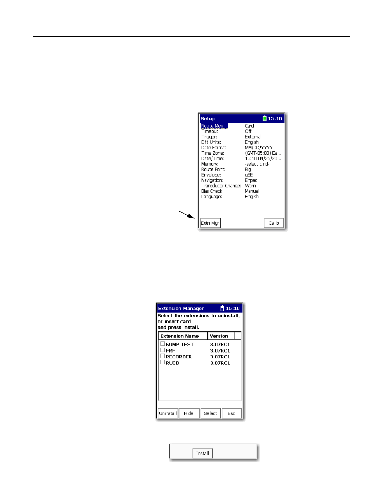
5. From the Main Menu, select Setup Utility and press Enter.
6. Press 0 (Shift) to display the second set of functions.
The Extension Manager function remains on the screen for about three
seconds after releasing 0 (Shift).
7. Press F1 (Extn Mgr).
The Extension Manager screen appears showing the current extension
module installations.
8 Rockwell Automation Publication 1441-UM004A-EN-P - May 2011
8. Press 0 (Shift) to display the Install Extension function.
9. Press F2 (Install) to install the new extension module.
Page 9
Installing Optional Extension Modules Chapter 3
Extension Manager
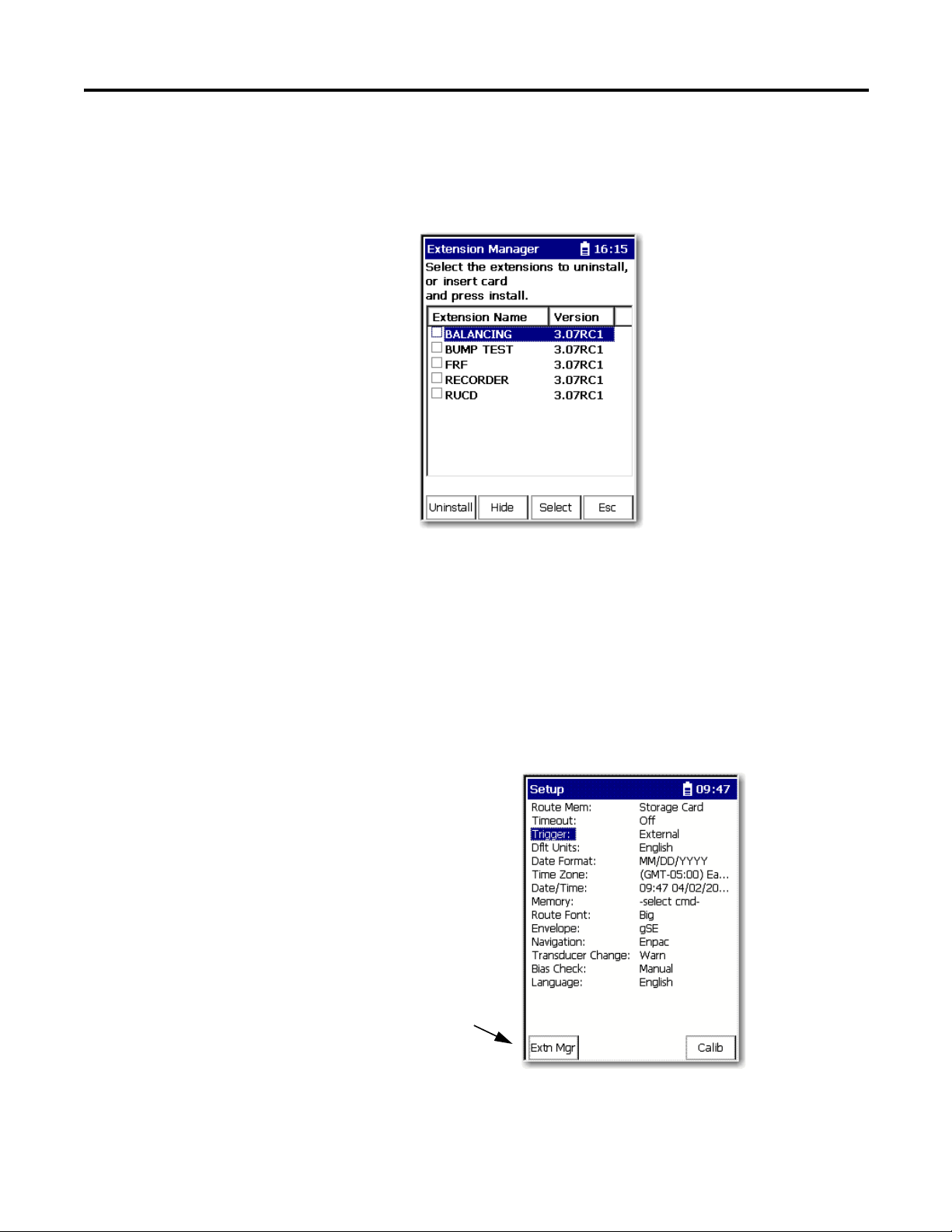
When the installation is complete, a confirmation prompt appears.
10. Press F4 (OK).
The new extension module appears in the list.
Uninstall Extension
Modules
11. Press F4 (Esc) to exit the Extension Manager screen.
Follow these instructions to uninstall an extension module.
1. Press 0 (Shift) from the Setup Utility screen to display the Extension
Manager function.
The Extension Manager function remains on the screen for about three
seconds after releasing 0 (Shift).
2. Press F1 (Extn Mgr).
Rockwell Automation Publication 1441-UM004A-EN-P - May 2011 9
Page 10
Chapter 3 Installing Optional Extension Modules
This screen lists the
extension modules
currently installed and the
on the unit.
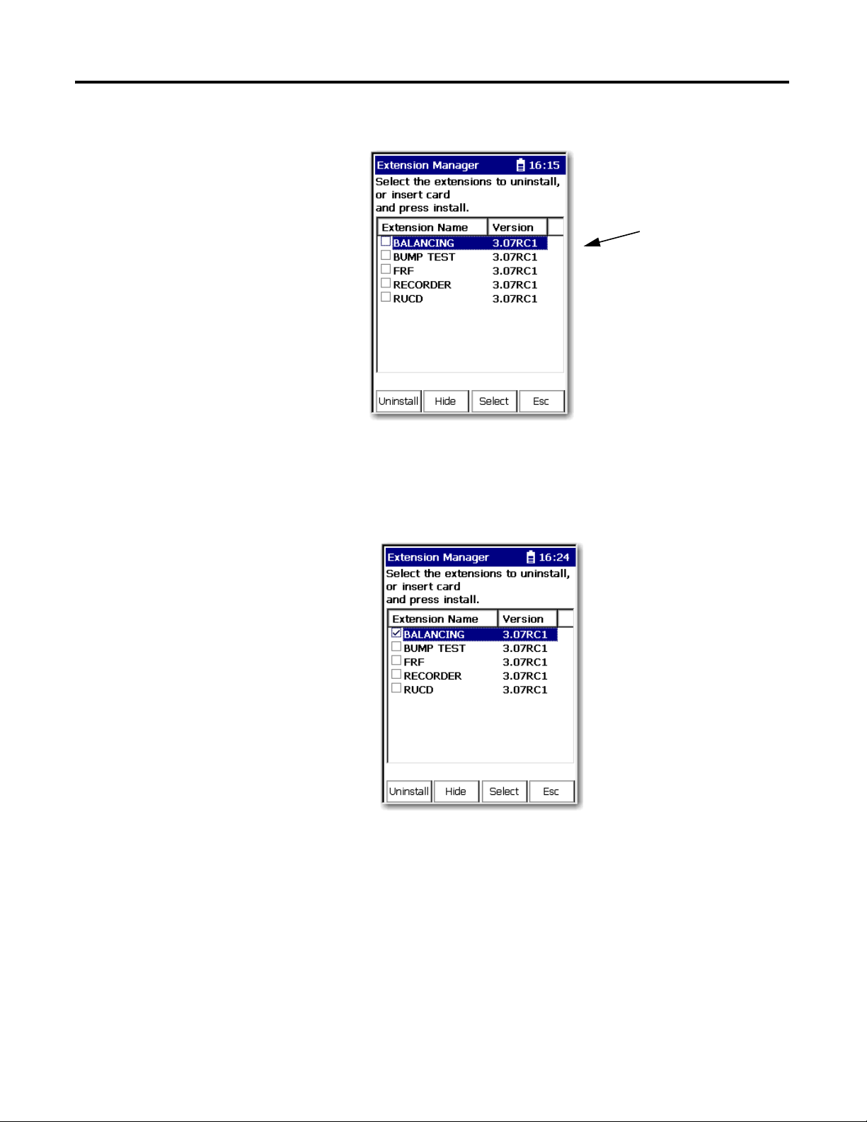
The Extension Manager screen appears.
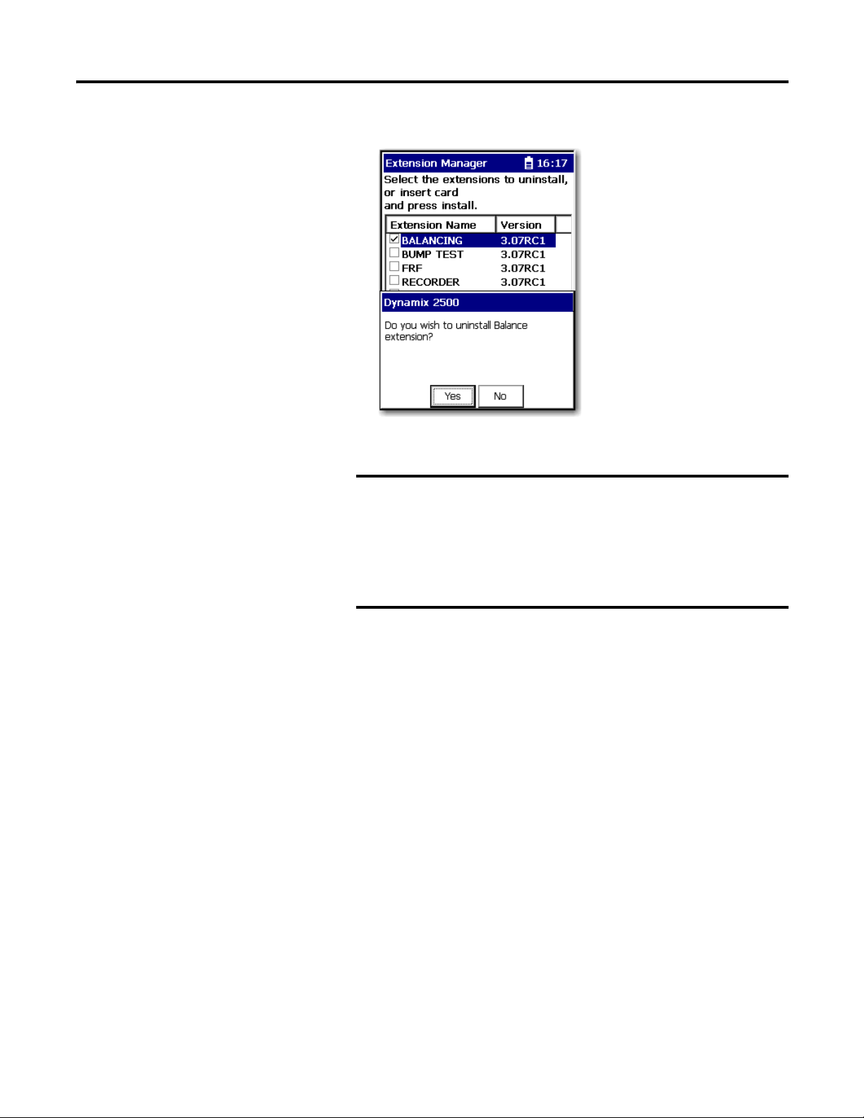
3. Select the extension module you want to uninstall and press F3 (Select).
F3 (Select) toggles the selection on and off.
A checkmark appears next to that extension module.
4. Press F1 (Uninstall).
10 Rockwell Automation Publication 1441-UM004A-EN-P - May 2011
Page 11
Installing Optional Extension Modules Chapter 3
IMPORTANT
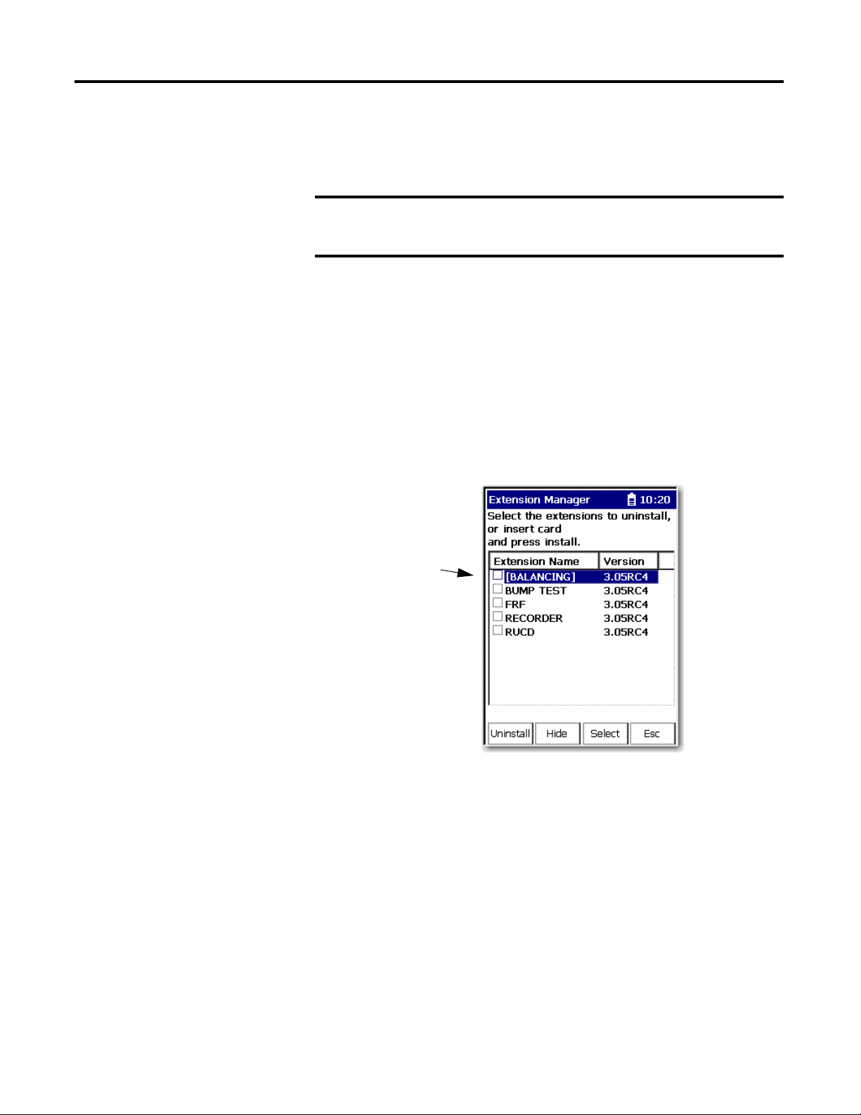
A confirmation message appears.
5. Make sure your installation card is inserted into the instrument.
The extension module is uninstalled and the license on the card is
released so that the card can be used to install the extension
module on another Dynamix 2500 data collector.
If the installation card is not inserted in the instrument and no
card, you are is found or the card does not have the extension
module license for the unit, you are prompted to insert the correct
installation card or continue without freeing the license.
6. Press F2 (Yes) to uninstall the extension module.
7. Press F4 (Esc) to exit the Extension Manager screen.
Rockwell Automation Publication 1441-UM004A-EN-P - May 2011 11
Page 12
Chapter 3 Installing Optional Extension Modules
IMPORTANT
TIP
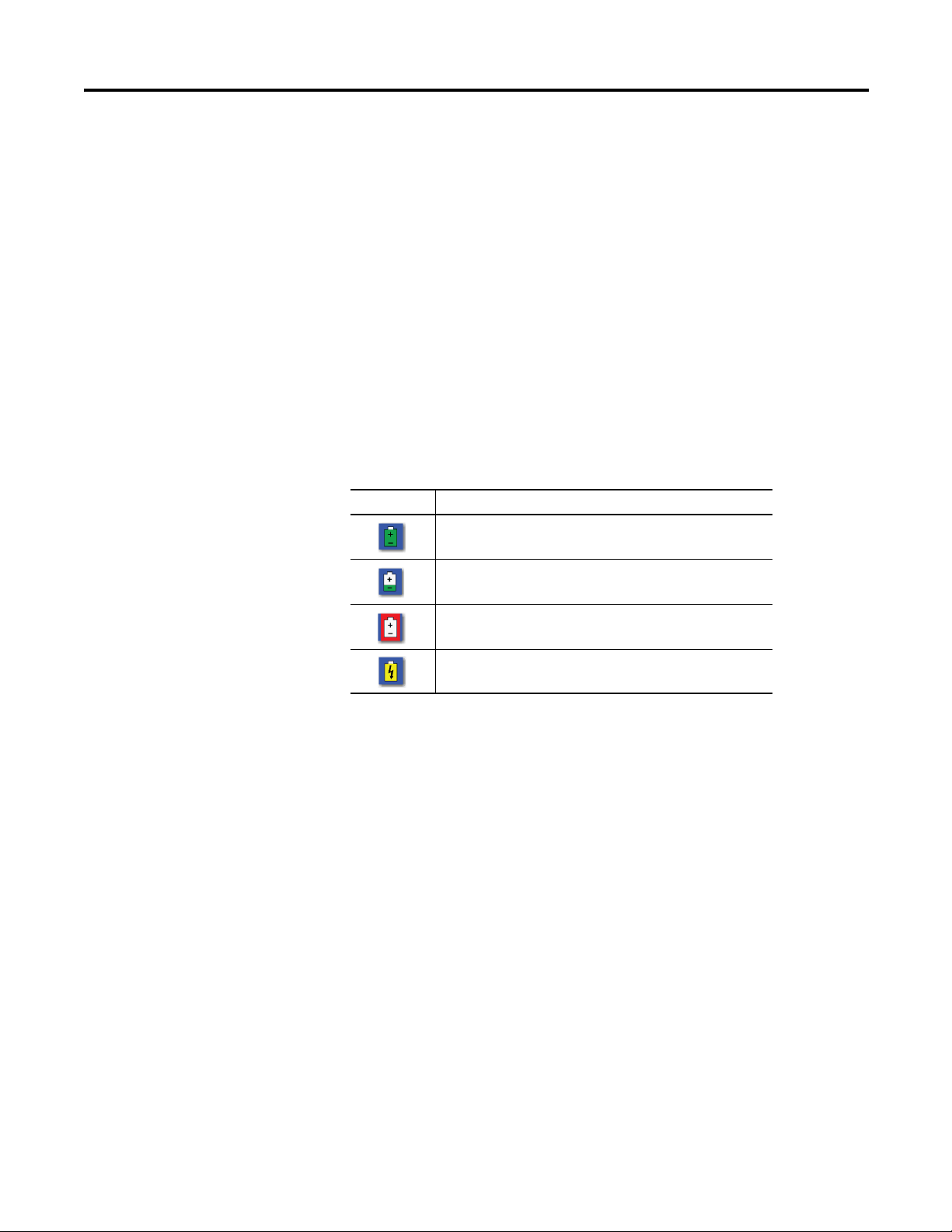
The extension modules that
are hidden are shown in
[square brackets].
Manage Extension
Modules
The Dynamix 2500 data collector lets you to hide installed extension modules
from the Main Menu. You may need to hide an advanced extension module icon
from an inexperienced user, for example, RUCD and FRF.
Once an extension module is hidden, its icon is not represented on the
Main Menu or displayed in the Dynamix 2500 data collector About
screen.
Follow these instructions to hide or show an extension module icon on the Main
Menu.
1. Press 0 (Shift) on the Setup Utility screen to display the Extension
Manager function.
The Extension Manager function should remain on the screen for
approximately three seconds after releasing 0 (Shift).
2. Press F1 (Extn Mgr). The Extension Manager screen appears.
The Extension Manager displays a list of installed extensions module.
12 Rockwell Automation Publication 1441-UM004A-EN-P - May 2011
The F2 (Hide) toggles between Hide and Show depending if the selected
extension module is hidden or not.
You have to exit and re-enter the Extension Manager after hiding an
extension module to have the Show function appear.
Page 13
Installing Optional Extension Modules Chapter 3
TIP
3. Select the extension module that you want to hide or show and press F2
(Show/Hide).
If you want to show or hide multiple extension modules
simultaneously, select each extension module and press F3
(Select).
A checkbox appears next to each selected extension module. If
you select multiple extension modules and some are hidden
while others are shown, F2 (Show/Hide) reflects the status of the
selected extension module.
4. Press F4 (Esc) to exit the Extension Manager.
Extension Module Battery
Status Indicators
The battery status icons show the strength of the battery.
Table 1 - Extension Module Battery Icon Descriptions
Battery Icon Meaning
Battery status is good: >30% life remaining.
Battery status is low: >10% life remaining.
Battery status is very low: <10% life remaining.
Battery is charging.
Rockwell Automation Publication 1441-UM004A-EN-P - May 2011 13
Page 14

Chapter 3 Installing Optional Extension Modules
Notes:
14 Rockwell Automation Publication 1441-UM004A-EN-P - May 2011
Page 15

Chapter
2
Balancing Extension Module
The Balancing extension module is an optional module for the Dynamix 2500
data collector. You install the extension module with the Balancing Secure Digital
(SD) storage card.
Topic Page
Balancing Measurements 16
Plane Balancing 16
Static-couple Balancing 18
Set Up the Balancing Parameters 20
Single Plane Balancing 26
Two Plane Balancing 45
Saving, Loading, and Reviewing Balance Measurements 61
Balancing application resolves single-plane, two-plane, and static-couple balances
with high precision. You can use the Dynamix 2500 data collector coupled with a
speed-measuring device such as a strobe light or laser tachometer.
The Dynamix 2500 data collector Balancing extension module provides a simple,
direct method to balance your rotating machinery in one or two planes. You can
use the internal laser tachometer in the data collector or an external laser
tachometer, optical tachometer, or strobescope for measuring phase during the
balance run.
Rockwell Automation Publication 1441-UM004A-EN-P - May 2011 15
Page 16

Chapter 2 Balancing Extension Module
Balancing Measurements
Balancing is the technique for determining the amount and location of the heavy
spot on a rotating shaft so that you can balance it with an equal amount of weight
in the opposite direction. These methods go through the technique with
stopping points where you start and stop the machine to perform weight addition
or subtraction.
There are three types of measurements in the balancing process:
• Initial Vibration
The initial vibration measurement is taken without any added weights on
the machine. The initial vibration measurement establishes a reference of
how the machine vibrates at each plane without any extra weight added.
This vibration is what will be corrected by the correction weight.
• Tri al Wei gh t
The trial weight measurements are taken with a single trial weight attached
to the machine at one plane or the other. The trial weight measurements
are used to determine how the machine is affected by the added weight.
The ideal trial weight should produce either a 30 % change in amplitude or
a 30
° change in phase.
• Residual Measurements
Plane Balancing
The residual measurements are taken with the correction weight or the
correction weight and trim weights attached to the machine. The
correction weight should cancel out the initial unbalance. A residual
vibration measurement is taken to measure the remaining unbalance. Trim
weights are added to the machine to cancel out the vibration measured
during a residual measurement.
Regardless of whether you are performing a single or two-plane balancing
procedure, all balancing procedures progress through basic runs as you start
(spin) and stop the rotor.
For two-plane procedures, you perform some of the runs twice, once with weights
on correction plane one and again with weights on correction plane two. For
simplicity, the following example describes a single-plane procedure.
These are the steps you need to take to take a single-plane balancing
measurement.
1. Set up balancing equipment and the Balancing parameters.
With the machine stopped, set up the balancing equipment and mark your
tachometer reference point on the rotor or shaft.
See Set Up the Balancing Parameters on page 20
measurement parameters for the balancing run sequence.
16 Rockwell Automation Publication 1441-UM004A-EN-P - May 2011
to configure balancing
Page 17

Balancing Extension Module Chapter 2
2. Perform the initial measurement.
a. Start the machine.
b. Take the initial measurement.
The initial measurement provides a starting place for balancing
computations. It records the machine's initial imbalance, 1X vibration
magnitude and phase angle. Later in the procedure, initial measurement
data is automatically compared with trial (weight) measurement data to
calibrate the machine's imbalance.
3. Attach a trial weight.
a. Stop the machine after collecting the initial measurement data.
b. Add a trial weight.
A trial weight is a temporary weight attached to produce a change from
the original unbalance readings (reference run readings). Input the trial
weight amount and placement angle into the data collector.
4. Perform the trial measurement.
a. Start the machine again with the trial weight securely attached.
b. Take trial measurement with the trial weight.
The trial measurement calibrates the machine's unbalance and allows
the data collector to calculate the influence coefficient and permanent
correction weight amount and placement. To allow for accurate
balancing computations, the trial weight should pass the 30/30 rule.
The trial weight should do the following:
• Increase or decrease the 1X vibration amplitude by at least 30 %
• Change the phase angle by at least 30
°
• Be a combination of A and B.
5. Attach the correction weight.
a. Stop the machine.
b. Remove the trial weight
c. Attach the specified correction weight at the specified angle.
6. Perform a correction weight measurement.
a. Start the machine again.
b. Take correction weight measurement.
The correction weight run performs two functions:
• It calculates the amount of residual imbalance with the correction
weight in place to confirm that the machine is now balanced within
tolerances.
• If further balancing is necessary, it automatically applies the
influence coefficient to calculate additional trim weights that can be
added to further balance the machine.
Rockwell Automation Publication 1441-UM004A-EN-P - May 2011 17
Page 18
Chapter 2 Balancing Extension Module
7. If additional trim weights are necessary to balance the machine within
tolerances, stop the machine and attach the specified trim weights.
a. Stop the machine.
b. Attach the specified trim weights.
c. Take another measurement.
8. Perform a trim measurement.
a. Start the machine.
b. Take a trim measurement to verify the machine is balanced within
tolerances. If not, you can take additional trim measurements.
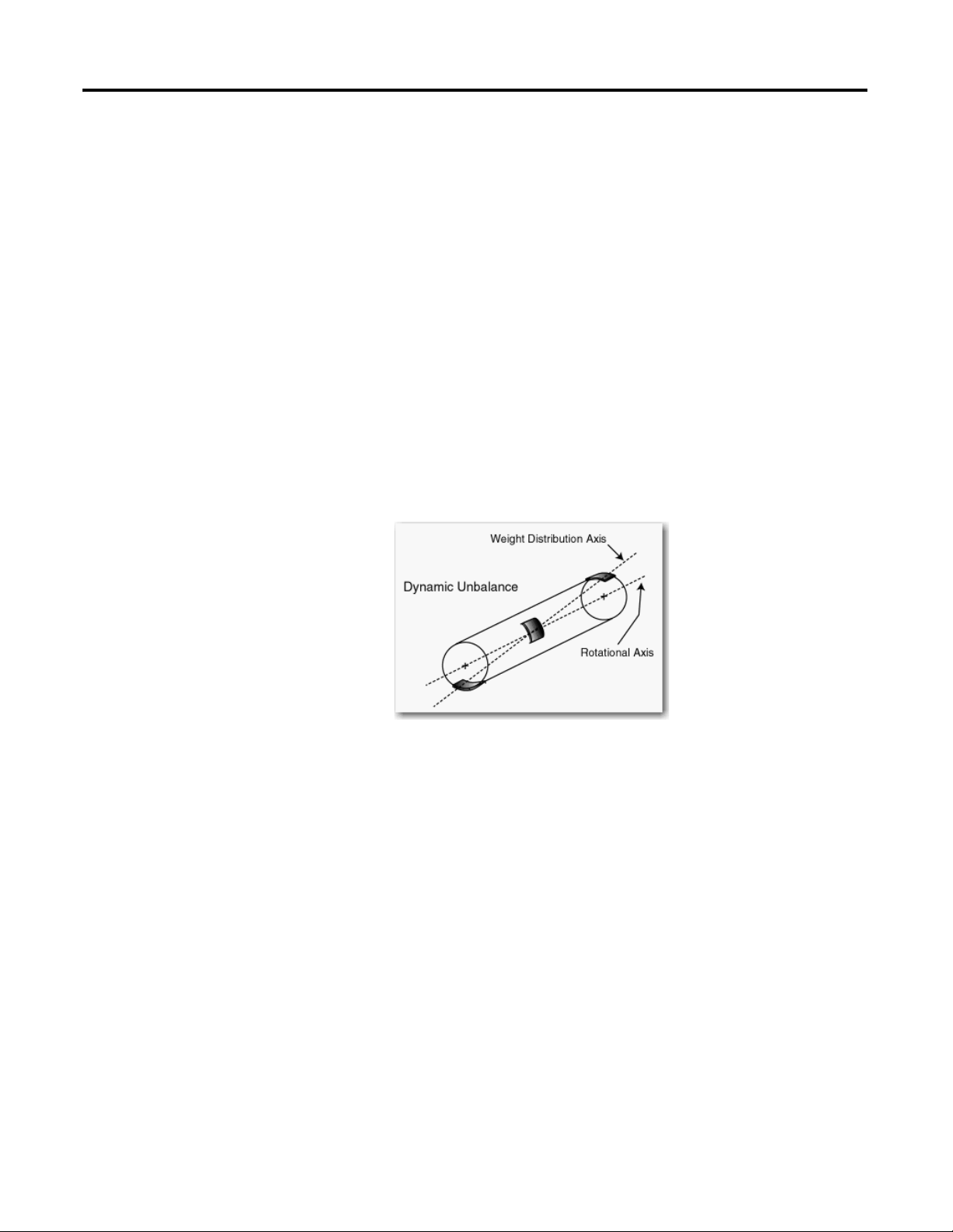
Static-couple Balancing
With stiffer rotors, a two-plane procedure may reduce the amount of imbalance
to target tolerances. However, with narrow or flexible rotors, more often a
static-couple procedure works best.
This graphic shows a narrow rotor showing three heavy spots.
The static-couple procedure corrects the static unbalance with weights added to
the center of gravity plane, and corrects the couple unbalance with weights added
to the end planes.
In practice, a static-couple balancing procedure is almost identical to a two-plane
balancing procedure, except that it provides three correction weight solutions
instead of two. One correction weight for each plane, and an additional
correction weight to correct the static unbalance.
Unless you are able to attach weights to the machine’s center of gravity plane, the
static weight is typically split in half and applied to the end planes to correct the
static unbalance.
In as such, on the data collector, the static-couple procedure is identical to the
two-plane procedure except the Correction Weight and Trim Weight screens
show three correction weights for the static-couple procedure:
• One weight for end plane 1
• One weight for end plane 2
18 Rockwell Automation Publication 1441-UM004A-EN-P - May 2011
Page 19
Balancing Extension Module Chapter 2
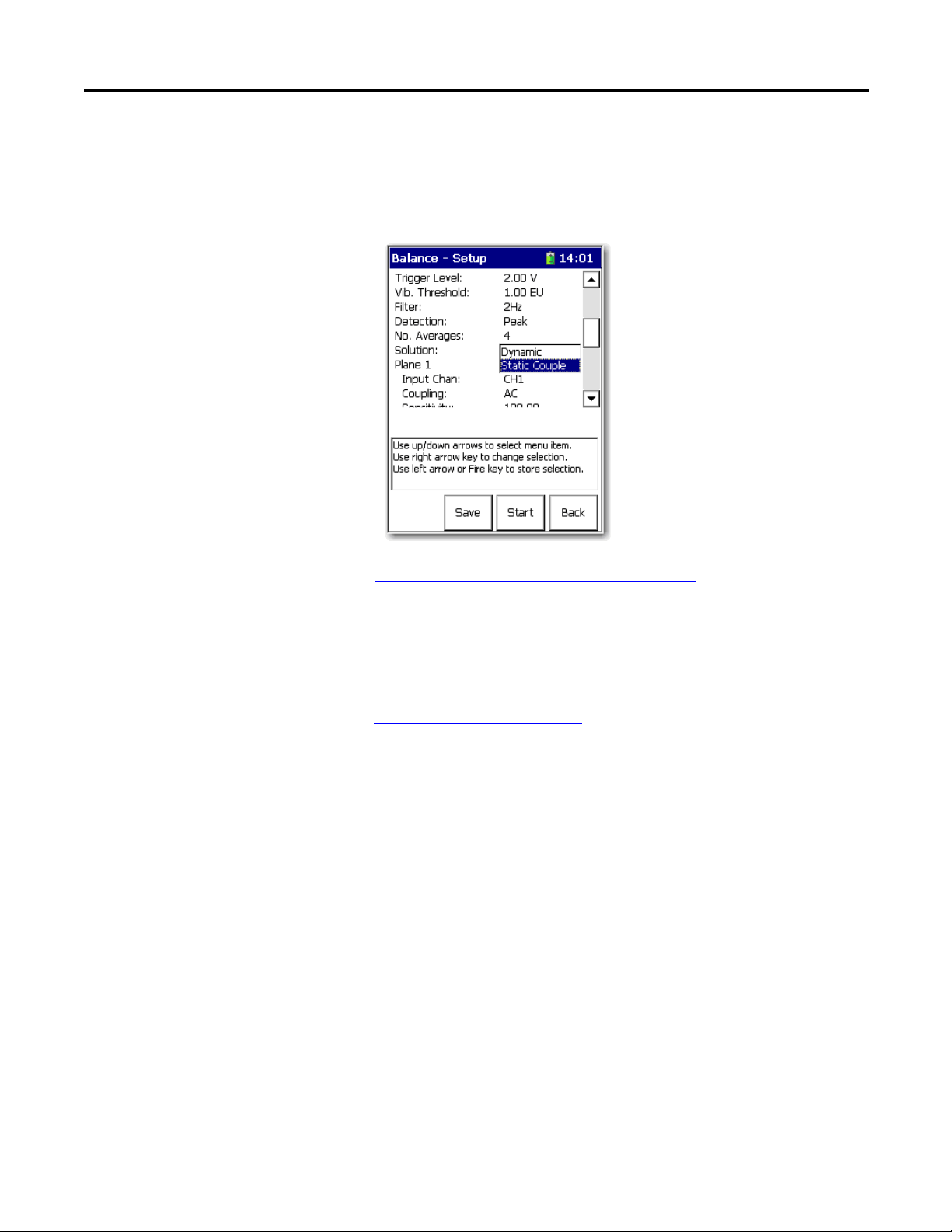
Except for the Solution field, all static-couple balancing parameters are identical
to two plane balancing settings.
If you want to compute three correction weights, select Static-Couple for the
Solution parameter on the Balance - Setup screen.
See Balance Extension Module Parameters on page 22
for more information
about these parameters.
Except for attaching three correction and trim weights instead of two (or four if
you split the static weight), all static-couple balancing run procedures are
identical to the two-plane balancing procedures.
SeeTwo Plane Balancing on page 45
on how to perform a two- plane Procedure
section for details.
Rockwell Automation Publication 1441-UM004A-EN-P - May 2011 19
Page 20
Chapter 2 Balancing Extension Module
Set Up the Balancing
Parameters
All balancing measurement parameters are set up from Balance Setup screen.
Follow these steps to go to the Balancing extension module.
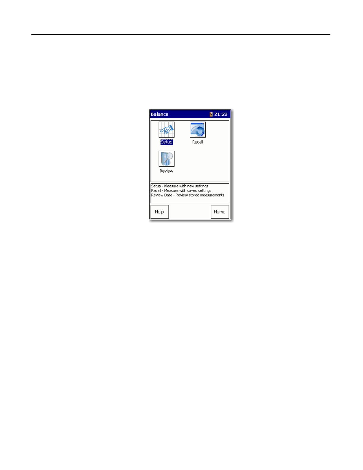
1. From the Main Menu, select Balancing and press Enter.
The Balance menu displays.
These are the Balance menu options:
• Setup
Access the Balance - Setup screen where you can set up and perform a new
balancing run.
• Recall
Access the Balance - Load Setup screen where you can select a previously
saved balancing run and perform a new run by using the saved settings.
• Review
Review Data screen where you can review previously stored measurements
or resume a previous balance measurement from the last completed run.
20 Rockwell Automation Publication 1441-UM004A-EN-P - May 2011
Page 21
Balancing Extension Module Chapter 2
Balance Setup Screen
After setting up your balance measuring equipment and marking your
tachometer reference point, the next step is to configure balancing measurement
parameters for the balancing run sequence.
Follow these steps to setup the Balancing parameters.
1. From the Balance main menu, select Setup and press Enter.
The Balance Setup lets you configure the balance measurement
parameters.
2. Select an option and press the Right arrow to open a list choices.
3. Use the arrow keys to select a parameter.
4. Press the Left arrow to save your selection.
Use the descriptions in Balance Extension Module Parameters
to help you
configure the parameters in the Balance Setup screen.
5. Save the setup or start taking the balancing measurement.
Rockwell Automation Publication 1441-UM004A-EN-P - May 2011 21
Page 22

Chapter 2 Balancing Extension Module
width
width
width
diameter
diameter
diameter
W/D RATIO 1-PLANE 2-PLANE
Less than 0.5
More than 0.5
but less than 2
More than 2
0 - 1000 RPM
0 - 150 RPM
0 - 100 RPM
Above
1000 RPM
150 - 2000
RPM or above
70% of 1st
critical
Above 100
RPM to 70%
of 1st critical
Table 2 - Balance Extension Module Parameters
Parameter Description Value
Num. of Planes Determines whether single-plane or two-plane balancing is
required. A good rule-of-thumb is the rotor’s width-to-diameter
(W/D) ratio. The W/D ratio is the width (excluding shaft length)
of the combine rotors divided by their diameter. The following
chart can be used to help determine whether to use one- or
two-plane balancing.
1
2 (default)
Num. Transducer Determines the number of transducers to be used. Connector A and B
Sensor (transducer) Type Vibration measurement type.
The type of vibration measurement depends on the type of
transducer used, for example, accelerometer, velocity pickup, or
proximity probe. This is required to establish integration
requirements for the FFT calculation.
Typically, accelerometers are used to perform velocity
measurements for field balancing procedures.
A Manual Entry option is available at the end of the list for
Accel (G) (default)
Vel IPS
Vel mm/s
Disp um
Disp mil
Manual Entry
manual balancing data entry, letting you to review and change
balancing run data. If selected, you are prompted to manually
enter the running speed, vibration magnitude, and phase angle
for the balancing runs.
Display Units Specify the unit of measurement for the select transducer type.
EU
The options available in the list vary depending on the
transducer selected.
Weight Units Defines the units used in balancing.
Specify the units of measurement used for your trial, correction,
and trim weights.
g
kg
oz (default)
lb
EU
22 Rockwell Automation Publication 1441-UM004A-EN-P - May 2011
Page 23

Balancing Extension Module Chapter 2
Table 2 - Balance Extension Module Parameters
Parameter Description Value
Length Units Specifies the units of measurement used for measuring the
radius of the weight placement (from the shaft center to the
position of the weight).
You can use this information when you have the data collector
to estimate the trial weight for you.
Movement Specify your weight angle placement convention, either With
Rotation or Against Rotation. During a balancing procedure,
when weight angle placements are specified, this setting
determines their direction from the zero reference point.
You place weights on the rotor to balance the machine. The
position of this weight is given in degrees or positions (where
the total number of positions equals the number of blades or
vanes) from the reference notch or mark. You must select
whether you are measuring the angle with or against the
direction of the shaft rotation.
The Movement parameter affects how the angles are
measured. If Movement is set to "With Rotn," angles are
measured from the reference mark, in the direction of the
machine’s normal rotation.
If Movement is set to "Against Rotn," angles are measured from
the reference mark, in the opposite direction of the machine’s
normal rotation.
Trigger Type Sets the trigger source:
• External Analog - An external trigger will be used to trigger
data sampling. You must also set the slope and trigger
level.
• Laser Tach - Enables the internal Laser Tachometer new
firmware and ext modules coming soon check SKF to
confirm this function. should be fixed
Ext trig slope Sets the slope for externally triggering the measurement.
Slope is the direction in which the signal is moving, and is
either positive (rising) or negative (falling) before a trigger is
detected.
This parameter is applicable only when Trigger Type is set to
ext Analog or ext TTL.
Trigger Level Amplitude level for the external trigger the measurement.
Enter the number of volts to eliminate noise, which may cause
false triggering.
This is applicable only for external analog trigger type
measurements.
Vib. Threshold The acceptable imbalance level you are trying to achieve. If the
vibration magnitude is greater than this threshold, the
magnitude bar is colored red when taking a reading. The bar
turns green when the selected level of imbalance is achieved.
Filter Sets the high pass filter to. apply to the measurement.
The high pass filter is useful in removing high vibration, low
frequency signal components, which can dominate the signal.
mm
cm
m
inch (default)
feet
EU
With Rotn
Against Rotn (default)
Ext Analog (default)
Laser Tach
-ve
+ve (default)
volts
2 V (default)
1.00 EU (default)
Off
2 Hz (default)
10 Hz
Rockwell Automation Publication 1441-UM004A-EN-P - May 2011 23
Page 24

Chapter 2 Balancing Extension Module
Table 2 - Balance Extension Module Parameters
Parameter Description Value
Detection Selects the type of signal detection and scaling for the
measurement:
• Peak - The data collector measures the dynamic signal
from zero to peak voltage. Use this or the RMS setting for
most acceleration and velocity measurements.
• Pk-Pk - The data collector measures the dynamic signal
from the minimum peak to the maximum peak. Use this
setting for most displacement measurements.
• RMS - The data collector measures the dynamic signal as
the square root of the mean of the square. Use this or Peak
for most acceleration and velocity measurements. Also use
this for voltage measurements.
No. Averages Enter the number of averages (1 to 8) for the measurement. 4 (default)
Solution Select the balancing solution. The parameter is available only
when you are two-plane balancing:
• Dynamic - The correction weights will be calculated for
both planes 1 and 2.
• Static-Couple - The correction weights will be calculated
as a combination of Static and Couple. The Couple balance
weights will be presented as the same weight in both
planes 1 and 2, with a phase angle of 180
° difference. The
Static part of the solution will be calculated at the center
between planes 1 and 2.
Peak: Scaled from RMS as 2
Pk-Pk: Scaled from RMS as 2
RMS: The Root Mean Squared overall
calculated from the FFT or time data.
Defaults to Peak for Accel
Defaults to Vel and Pk-Pk for Disp.
Dynamic (default)
Static-Couple
RMS
2 RMS
24 Rockwell Automation Publication 1441-UM004A-EN-P - May 2011
Page 25

Balancing Extension Module Chapter 2
Input Chan The input channel required for the measurement.
Select channel X for single-plane balancing, with the
transducer connected to the data collector’s Connection A.
For two-plane balancing with two transducers, you set one
plane’s transducer as channel X, the other plane’s transducer as
channel Y.
See Two Plane Balancing on page 45
for more information.
X (default) on connector A only
Y, on Connector B
Coupling The type of coupling to be applied to the measurement.
• AC, Acquires the input signal from a buffered output
(external) device. Power is not applied to the transducer.
• ICP, Applies DC to the charge amplified transducer signal
and couples the dynamic signal to the input channel.
AC
ICP
(default)
Sensitivity The sensitivity of the transducer. Sensitivity is set as mV/EU,
where EU is the base engineering unit of the transducer.
Use the keypad to enter the transducer sensitivity in millivolts
(mv) per Engineering Unit (EU). 100 mV/EU is used for most
acceleration transducers, 200 mV/EU for most non-contact
displacement transducers, and 1000 mV/EU if the input is volts
and the scales is to be read directly. The default setting is 100
mV/EU.
0.010 to 1000 mV/EU
A 100 m V/G accelerometer
would be set as 100 m V/EU
Input Range Select the signal input range between Autorange and a fixed
range in transducer units in a 1 - 2 - 5 sequence. The available
fixed values vary depending on the transducer type being used.
If a fixed range is selected and the data collector detects an
over range, it automatically selects the next higher range until
it does not over range.
Autoranging
Type Select the appropriate weight position type,
For a rotor without vanes or blades, set Type to Continuous.
Continuous specifies that weights may be placed at any
placement position on the balance plane.
Fixed is known also as vector splitting. It works with Number of
Positions and Position 1 Offset fields. Fixed specifies that
weights may be placed only at designated positions, for
example, rotors having a specific weight hole pattern, or with a
specific number of fan blades.
Continuous (default)
Fixed
No. of posns Applies to Fixed weight position measurements only.
The first position defaults to 0
°, subsequent positions evenly
spaced.The number of positions refers to the number of rotor
components, such as blades on a fan.
3 to 360
°
Enter 0 (zero) for a rotor without
vanes or blades.
Posn 1 Offset Applies to Fixed weight position measurements only.
Enter the fixed position 1 offset, from zero to 360
°, relative to
the trigger reference.
0 to 360
°
Table 2 - Balance Extension Module Parameters
Parameter Description Value
Plane (x) Sets the plane for which the settings below apply.
Two plane get two sets of the following attributes/parameters
(settings)
1
2
Rockwell Automation Publication 1441-UM004A-EN-P - May 2011 25
Page 26

Chapter 2 Balancing Extension Module
Single Plane Balancing
The balancing of a machine in one plane is divided into taking these three
measurements:
• Initial measurement
• Trial weight measurement
• Residual measurement
You must complete the entire procedure until the vibration level has been
reduced enough for your needs.
See Balancing Measurements on page 16
for more information.
Single Plane Balancing Procedure Overview
This is an overview of the steps you need to take when performing a single plane
balancing measurement.
1. Take the Initial Vibration Measurement on page 27
2. Add the Trial Weight on page 28
a. Enter the Trial Weight Manually on page 29
b. Estimate the Trial Weight on page 30
.
.
.
.
3. Take a Trial Run Weight Measurement on page 32
4. Take a Cor rect ion Run on p ag e 35
5. Perform a Trim Run on page 37
6. Combine the Balance Run Weights on page 38
7. Add the Correction Weight and Take a Residual Measurement on page 41
a. Split the Correction Weight on page 42
b. Modify the Radius on page 42
c. Add or Remove Weight on page 42
d. Take the Residual Measurement on page 42
.
.
.
.
.
.
.
.
.
26 Rockwell Automation Publication 1441-UM004A-EN-P - May 2011
Page 27

Balancing Extension Module Chapter 2
TIP
IMPORTANT
TIP
Take the Initial Vibration Measurement
The initial vibration measurement is taken without any added weights on the
machine. The initial vibration measurement establishes a reference of how the
machine vibrates at each plane without any extra weight added. This vibration is
what will be corrected by the correction weight.
Skip step 1 if you are using the internal Laser
Tachometer as the trigger source.
1. If you are using an external tachometer, optical tachometer, or strobescope
as the trigger source, then connect the tachometer cable to the POWER/
USB/TRIGGER connector at the top of the data collector.
2. Attach a transducer to the machine to be balanced.
3. Mark the rotor by making a mark on one rotor that will serve as a reference
mark.
It is also possible to use an existing mark on the rotor as the reference mark,
such as a key or keyway.
If the rotor has multiple positions (vanes or fan blades), the
reference mark must be at one of the blade positions.
4. Start the machine and allow it to reach normal running speed.
5. Press Enter to take the initial vibration measurement.
Depending on your setup, the Dynamix 2500 data
collector may ask if the transducer is attached to
plane 1. If the transducer is attached, press F4 (OK).
Rockwell Automation Publication 1441-UM004A-EN-P - May 2011 27
Page 28

Chapter 2 Balancing Extension Module
IMPORTANT
TIP
Running Speed
Vibration Magnitude and Phase
Phase Angle and
Magnitude Diagram
The data collection begins as soon as the trigger conditions are satisfied.
The Dynamix 2500 data collector automatically measures the speed,
vibration, and plane. The values are continually updated on the screen.
Note the speed reading at the top of the display. For accurate balancing
results, it is important to maintain the same speed across all balancing
runs.
It is recommended that you save the initial run so that you do not have to
repeat it. Then you can update the saved file with subsequent runs.
6. When the speed, vibration, and phase values are stable, press Enter to
complete the initial vibration measurement.
The results are stored in the Vibration Summary Table.
7. Shut down the machine and continue the balancing procedure.
Anytime during the initial run, you can do the following:
• Press F4 (Esc) to exit the balancing module.
• Press the 0 (Shift) key and F1 (Go to) to simultaneously go back to
a previous step in the balance run.
See Move Around in a Balance Run on page 60
for details.
• Press F2 (Summary) to display the results in the Vibration
Summary Table.
28 Rockwell Automation Publication 1441-UM004A-EN-P - May 2011
Add the Trial Weight
The Add Trial Weight screen appears when the initial run measurement is
complete.
You can manually enter the trial weight, the angle, and the radius, or you can have
the data collector automatically estimate the trial weight for you.
Page 29

Balancing Extension Module Chapter 2
Enter the Trial Weight Manually
Follow these instructions to manually enter the trial weight you are attaching to
the machine. A negative number can be entered if trial weight is removed, instead
of added. Trial weights are typically attached at 0° (the trigger reference). Unless
you wish the data collector to estimate a trial weight, the Radius entry is not
necessary, so long as you position the trial, correction, and trim weights at the
same radius.
1. On the machine, carefully attach the precise weight at the precise angle and
radius specified.
Balancing results depend greatly on the precision of your measurements
and actions.
2. Use the Up/Down arrows to select the parameters and the Right arrow to
enter trial weight, angle, or radius value by using the numeric key pad.
In the Mass parameter, enter the trial weight. Enter rotor mass supported
in this plane (in the Weight Units specified on the Balance Setup screen).
Use total rotor mass for single plane and 50% of mass for two plane.
3. In the Angle parameter, enter the location (in degrees) of the trial weight
on the rotor.
The trial weight’s Angle placement is typically zero. The angle is measured
from the reference mark in the direction specified in the Movement
parameter in the Balance Setup screen.
See Set Up the Balancing Parameters on page 20
for additional
information.
4. In the Radius parameter, enter the radius of the trial weight.
5. Press OK.
Rockwell Automation Publication 1441-UM004A-EN-P - May 2011 29
Page 30

Chapter 2 Balancing Extension Module
Trial Weight
.1 rotor mass 9.81 900
radius [speed 2
--------------------------------------------------------------------
=
You are returned to the Add Trial Weight screen where the estimated trial
weight displays in both the Mass and Estimated Mass fields.
Estimate the Trial Weight
At times, you may want the data collector to calculate the trial weight for you.
The Trial Weight Estimate is based on the criteria that the trial run centrifugal
force does not exceed 10% of the bearing shaft load.
The Dynamix 2500 data collector calculates the trial weight (mass), the angle,
and the radius by using the following formula.
Follow these instructions to estimate the trial weight.
1. From the Add Trial Weight screen, enter the trial weight’s Angle placement
(typically zero) and Radius.
2. Press F3 (Estimate).
You are prompted to enter the rotor’s mass support in this plane.
3. Enter rotor mass supported in this plane (in the Weight Units specified on
the Balance Setup screen).
30 Rockwell Automation Publication 1441-UM004A-EN-P - May 2011
Use total rotor mass for single plane and 50% of mass for two plane.
4. Press F2 (OK).
You are returned to the Add Trial Weight screen where the estimated trial
weight displays in both the Mass and Estimated Mass fields.
Page 31

Balancing Extension Module Chapter 2
TIP
TIP
5. When the speed, vibration, and phase values are stable, press Enter.
The trial weight measurement is complete and the results are stored in the
Vibration Summary Table.
A message appears asking if the trial weight is still attached:
• Press F2 (Yes) if the weight is still attached to the rotor.
• Press F3 (No) if the weight has been removed from the rotor.
It is good practice to remove the trial weight.
6. Shut down the machine.
Anytime during the initial run, you can do the following:
• Press F4 (Esc) to exit the balancing program.
• Press 0 (Shift) and F1 (Go to) simultaneously to go back to a
previous step in the balance run.
See Move Around in a Balance Run on page 60
• Press F2 (Summary) to display the results in the Vibration
Summary Table.
See Review Balancing Measurements on page 63
for details.
for details.
Rockwell Automation Publication 1441-UM004A-EN-P - May 2011 31
Page 32

Chapter 2 Balancing Extension Module
Take a Trial Run Weight Measurement
The trial weight measurements are taken with a single trial weight attached to the
machine at one plane or the other. The trial weight measurements are used to
determine how the machine is affected by the added weight. The ideal trial
weight should produce either a 30 % change in amplitude or a 30 ° change in
phase.
Follow these instruction to take a trial weight measurement.
1. With the trial weight securely attached to the machine, start the machine
and bring it back up to the same speed used with the initial run.
2. Press Enter to start taking trial weight measuremnt.
The Trial Run 1 screen shows vibration magnitude and phase readings
with the trial weight attached. For accurate balancing efforts, these
readings should satisfy the 30/30 rule. From the reference run, the trial
weight causes a 30% change in magnitude, or a 30 degree change in phase,
or both. The Dynamix 2500 data collector automatically analyzes the data
to determine if the 30/30 rule is being met.
• The Trial Run magnitude is between 70% and 130% of the Initial Run
magnitude, and the Trial Run phase is within ±30 of the Initial Run phase,
the 30/30 rule is not being met, this warning appears:
32 Rockwell Automation Publication 1441-UM004A-EN-P - May 2011
Page 33

Balancing Extension Module Chapter 2
• If the Trial Run magnitude is over 200% of the Initial Run magnitude, this
warning appears:
3. In either case, press F2 (Yes) to return to the Add Trial Weight – Plane 1
screen where you can adjust your settings or press F3 (No) to continue with
the current settings.
With the 30/30 rule satisfied, the data collector uses differences between
the reference run readings and trial run readings to compute the influence
coefficient, which it uses to compute the permanent correction weight
solution.
4. If you need to, correct any values.
5. From the Trial Weight Measurement screen, press Enter to proceed.
Before computing the correction weight solution, you are prompted to
indicate whether the trial weight is to remain attached or be removed.
Trial weights are normally temporary, and removed before one final
correction weight is attached. However, sometimes the trial weight must
be permanently attached for safety purposes, and is therefore left on the
machine.
6. Select No, as you typically plan to remove the temporary trial weight (or
select Yes if you plan to leave the trial weight attached).
Rockwell Automation Publication 1441-UM004A-EN-P - May 2011 33
Page 34

Chapter 2 Balancing Extension Module
The Correction Weight – Solution screen displays.
7. From the Correction Weight Solution screen, press Enter to begin the
correction run.
The Correction Weight – Solution screen displays fields at the top of the
screen, and the permanent correction weight mass, angle, and radius
balance solution for the field settings.
Parameter Description
Split Mass? Sometimes a weight cannot be placed at the angle specified by balancing
Weight Add/Subtract Specifies whether you are adding or subtracting the correction weight.
Radius Lets you to specify a new weight placement radius. Mass and Angle
Angle (1) / Angle (2) Applicable only if you split weights. Lets you to specify the placement angle
computations. The Split Mass? option automatically splits the specified
weight into two weights positioned at two placement angles around the
original angle.
Mass and Angle settings automatically adjust per your selection. Defaults
to Add.
settings automatically adjust for the new radius. If you split weights, a
radius setting is available for each weight.
for the two weights. Both angles must be specified for weight recalculation.
The data collector recalculates the weight for each position based on the
relative phase between the correction weight and the split weight locations.
8. Stop the machine, remove the temporary trial weight, and securely attach
the permanent correction weight at the precise angle and radius specified.
34 Rockwell Automation Publication 1441-UM004A-EN-P - May 2011
Page 35

Balancing Extension Module Chapter 2
If the vibration magnitude is
greater than this threshold, the
magnitude bar is colored red
when taking a reading. The bar
turns green when the selected
level of imbalance is achieved.
Take a Correction Run
The Correction Run screen displays, showing the amount of residual unbalance
with the correction weight attached.
Verify whether the amount of residual unbalance is within specifications for the
machine. If the amount of residual imbalance is within specifications, you can end
the balance measurement, if not, you should proceed with a trim run.
1. Press Enter.
You are prompted whether you wish to perform7 a trim run.
The data collector automatically measures the speed, vibration, and phase.
The values are constantly updated on the screen.
2. If necessary, press Yes to proceed with a trim run.
Rockwell Automation Publication 1441-UM004A-EN-P - May 2011 35
Page 36

Chapter 2 Balancing Extension Module
The Trim 1 Weight - Solution screen displays the trim weight data (or press
No to end the balance measurement).
3. If Necessary, attach a Trim Weight.
The Trim 1 Weight – Solution screen displays the trim weight mass, angle,
and radius to help balance the residual.
4. Stop the machine and securely attach the permanent trim weight at the
precise angle and radius specified.
36 Rockwell Automation Publication 1441-UM004A-EN-P - May 2011
Page 37

Balancing Extension Module Chapter 2
Perform a Trim Run
You can repeat trim runs until you are satisfied that you have the finished the
balancing measurement.
Follow these instructions to perform a Trim Run.
1. With the trim weight securely attached, start the machine and press an
Enter button to perform the trim run.
The Trim Run 1 screen displays the amount of residual unbalance with the
trim weight attached.
2. Verify whether the amount of residual unbalance is within specifications
for the machine.
If the amount of residual unbalance is within specifications, you can end
the balance measurement, if not, you should proceed with another trim
run.
3. Press Enter to proceed.
When you press No to the Trim Residual? prompt, the Vibration Summary
screen automatically displays a summary of your measurement’s balancing data.
The Summary function button is available from all balancing screens.
4. Press F2 (Summary) to display your procedure’s Vibration Summary Table.
The Vibration Summary Table screen displays all magnitude and phase
values for each run performed during your balancing procedure.
Rockwell Automation Publication 1441-UM004A-EN-P - May 2011 37
Page 38

Chapter 2 Balancing Extension Module
5. Press the F2 (Wts) to display the Weights Summary Table screen.
The Weights Summary screen appears.
The Weights Summary Table screen displays the mass, angle, and radius for your
trial, correction, and trim weights. If the correction or trim weights are split (in
the continuous case) or fixed positions are chosen, then the two sets of correction
weights display sequentially. An asterisk next to a trial weight indicates that the
weight has been removed.
Combine the Balance Run Weights
After your balancing runs, you may want to combine your correction and trim
weights into a single weight.
Follow these steps to access the combine weights screen.
1. From the Weights Summary Table, press F2 (Comb Wt.).
38 Rockwell Automation Publication 1441-UM004A-EN-P - May 2011
Page 39

Balancing Extension Module Chapter 2
2. Select the weights you wish to combine and press F3 (Select, this function
also deselects) each weight.
A checkmark appears next to selected weights.
3. After selecting all the weights you wish to combine into one, press F2
(Accept) to compute your combined weight.
You are prompted whether you wish to remove all selected weights and
combine with one weight?
4. Press F2 (Yes) to proceed.
Rockwell Automation Publication 1441-UM004A-EN-P - May 2011 39
Page 40

Chapter 2 Balancing Extension Module
You are prompted to enter the radius for the combined weight.
5. Enter the combined weight’s placement radius and press F2 (OK).
The Combine Weights screen re-displays, showing the new combined
weight’s mass, angle, and radius.
6. Press F4 (Esc) to return to previous screens.
7. Remove the weights specified for removal, and attach the final combined
weight at the precise angle and radius specified.
40 Rockwell Automation Publication 1441-UM004A-EN-P - May 2011
Page 41

Balancing Extension Module Chapter 2
F3 (Memory) take you to
the Save Setup screen if
you want to save your
Solution.
Add the Correction Weight and Take a Residual Measurement
The residual measurements are taken with the correction weight or the correction
weight and trim weights attached to the machine. The correction weight should
cancel out the initial unbalance. A residual vibration measurement is taken to
measure the remaining unbalance. Trim weights are added to the machine to
cancel out the vibration measured during a residual measurement.
The Dynamix 2500 data collector calculates and displays a recommended
balancing weight in the Correction Weight - Solution screen.
You can split the correction weight into two distinct angles, as well as modify the
radius of the correction weight. Additionally, the Dynamix 2500 data collector
calculates the amount of weight that might be removed if weights are already
attached to the rotor.
When you need to save the Correction Weight solution, press F3 (Memory.
Rockwell Automation Publication 1441-UM004A-EN-P - May 2011 41
Page 42

Chapter 2 Balancing Extension Module
Split the Correction Weight
On many rotors, such as a fan, it is not possible to correct the unbalance at the
angle indicated by a measurement run. The Dynamix 2500 data collector lets the
correction to be split into two components at points where it is possible to add or
remove weight.
Follow these instructions to split the correction weight.
1. Select Split Mass, then press the Right arrow key.
2. Select Yes to split the weight and press the Left arrow key to save your
choice.
The Dynamix 2500 data collector calculates the weight and displays the
new recommendation at the bottom of the screen.
3. To unsplit the correction weight, repeat steps 1 and 2 and select No.
Modify the Radius
Follow these instructions to modify the radius.
1. Select Radius, and press the Right arrow key.
2. Use the key pad to enter a new radius value and press the Enter key to save
your entry.
The data collector calculates the weight and displays the new
recommendation at the bottom the screen.
Add or Remove Weight
Follow these instructions to add or remove weight.
1. Select Weight and press the Right arrow.
2. Select Add or Subtract, and press the Left arrow key to save your choice.
The Dynamix 2500 data collector calculates the weight and displays the
new recommendation at the bottom the screen.
Take the Residual Measurement
Follow these instructions to take a residual measurement.
1. Attach the correction weight to the rotor.
2. Start the machine and let it reach operating speed.
3. Press Enter to take a residual measurement.
42 Rockwell Automation Publication 1441-UM004A-EN-P - May 2011
Page 43

Balancing Extension Module Chapter 2
TIP
IMPORTANT
The data collector automatically measures the speed, vibration, and phase.
The values are constantly updated on the screen.
4. When the speed, vibration, and phase values are stable, press Enter.
The residual measurement is complete.
The green status indicator illuminates when the
measurement is complete.
• Amber is waiting for data acquisition
• Red ICP or overrange detection fault.
5. Do one of the following.
• Press F2 (Yes) to trim the residual. The data collector calculates the trim
correction weights and displays the following screen.
You can split the trim weight and modify the radius.
• Press F3 (No) if you do not want to trim the residual.
The Vibration Summary Table appears.
See Split the Correction Weight on page 42
for details.
6. Shut down the machine and attach the trim weight(s) whose weight, angle,
and radius are indicated on the screen.
Do not remove the original correction weight.
7. Start the machine and let it reach operating speed.
8. Press Enter.
Rockwell Automation Publication 1441-UM004A-EN-P - May 2011 43
Page 44

Chapter 2 Balancing Extension Module
The data collector takes vibration readings, calculates new trim weight(s)
and displays the values.
• If the rotor is still out of balance, repeat adding the trim weight and
taking residual measurements until the rotor is properly balanced.
• If several trim correction runs have been performed (resulting in several
trim weights), values may be combined into one permanent trim
weight.
• If the balance never improves, check to see if you entered the correct
trial weight size and location, or check other factors such as
misalignment or a faulty bearing.
However, if the vibration has been reduced to an acceptable level,
balancing is complete.
9. Save your balancing data, if desired, by pressing F3 (Memory).
See Save a Balance Measurement on page 61
for details.
44 Rockwell Automation Publication 1441-UM004A-EN-P - May 2011
Page 45

Balancing Extension Module Chapter 2
Two Plane Balancing
With two-plane balancing, the measurement sequence proceeds in the same
order as with single-plane balancing, except two trial weights and two trial runs
are required to calculate four influence coefficients (only one influence
coefficient exists for single-plane).
The balancing of a machine in two planes is divided into taking these three
measurements:
• Initial measurement
The initial vibration measurement is taken without any added weights on
the machine. The initial vibration measurement establishes a reference of
how the machine vibrates at each plane without any extra weight added.
This vibration is what is corrected by the correction weight.
• Trial weight measurement
The trial weight measurements are taken with a single trial weight attached
to the machine at one plane or the other. The trial weight measurements
are used to determine how the machine is affected by the added weight.
The ideal trial weight should produce either a 30 percent change in
amplitude or a 30 ° change in phase.
• Residual measurement
The residual measurements are taken with the correction weight or the
correction weight and trim weights attached to the machine. The
correction weight should cancel out the initial unbalance. A residual
vibration measurement is taken to measure the remaining unbalance. Trim
weights are added to the machine to cancel out the vibration measured
during a residual measurement.
See Balancing Measurements on page 16
for details about these measurements.
Rockwell Automation Publication 1441-UM004A-EN-P - May 2011 45
Page 46

Chapter 2 Balancing Extension Module
Two Plane Balancing Procedure Overview
This is an overview of the steps you need to take when performing a two plane
balancing measurement.
1. How to Set Up a Two-Plane Procedure on page 46
2. Set-up Options Specific to Two-plane Balancing on page 47
3. How to Perform Two-plane Balancing on page 50
4. Perform the Initial Runs on page 50
5. Two-plane Balancing with One Transducer on page 51
6. Perform Trial Run 1 on Both Planes on page 53
7. Perform Trial Run 2 on Both Planes on page 54
8. Perform Correction Weight Runs on Both Planes on page 55
9. Perform Trim Runs on both Planes on page 58
.
.
.
.
.
.
.
.
.
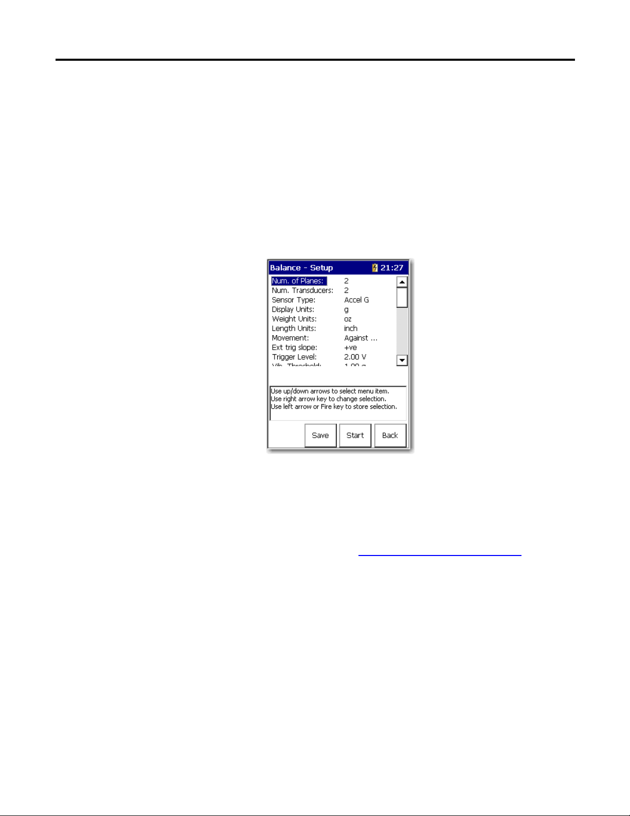
How to Set Up a Two-Plane Procedure
Specific differences exist between single and two-plane balancing measurement
field settings. Setup options specific to two-plane procedures are detailed below.
See Single Plane Balancing on page 26
both single and two-plane balancing.
Figure 1 - Balance Setup Screen with 2 Planes Selected.
46 Rockwell Automation Publication 1441-UM004A-EN-P - May 2011
section for all other settings that apply to
Page 47

Balancing Extension Module Chapter 2
IMPORTANT
Specific differences exist between single and two-plane balancing measurement
field settings. Setup options specific to two-plane procedures are detailed below.
See Single Plane Balancing on page 26
section for all other settings that apply to
both single and two-plane balancing.
Set-up Options Specific to Two-plane Balancing
Adjust these settings on the Balance Setup screen for a two-plane procedure.
See Balance Extension Module Parameters on page 22
1. Enter 2 for Num. of Planes to specify a two-plane balancing procedure.
Other setup fields may adjust to display options specific to two-plane
balancing.
2. Select whether or not you are using one or two transducers in the Num.
Transducers field.
• Select one if you are moving a single transducer between channel 1 and
channel 2 to collect the measurements.
• Select 2 to affix a transducer to each plane (using Connector A and
Connector 2 on the data collector) and take both measurements
simultaneously.
If using only one transducer, you must also specify the same input
channels for both Plane 1 and Plane 2 sections.
For two transducer balancing, you must also specify X and Y input
channels for Plane 1 and Plane 2 sections.
for descriptions.
3. In the Solutions field, select whether or not you are using a Dynamic or
Static-Couple
• Select Dynamic to compute two correction weight solutions for a
two-plane balancing procedure.
• A Static-Couple option is available for situations where you wish to
compute three correction weights, one to correct the static unbalance,
and two to correct the couple unbalance (static-couple balancing).
See Static-couple Balancing on page 18
for more information about the
Static Couple parameter.
4. Select Plane 1/Plane 2 – When setting up two planes, the Balance - Setup
screen expands to include a section for Plane 2 settings.
• When two-plane balancing with one transducer, the Input Channel,
Coupling, Sensitivity, and Input Range are set on Plane 1 and apply to
both planes.
Rockwell Automation Publication 1441-UM004A-EN-P - May 2011 47
Page 48

Chapter 2 Balancing Extension Module
5. Use the Input Channel, Coupling, Sensitivity, Input Range, Type, Number
of Positions, and Position 1 Offset fields to set up each balancing plane’s
transducer and weight placement settings for the following balancing
setups.
• One transducer/Two Identical Planes
When two-plane balancing with one transducer (where the balancing
planes are identical), set the Input Channel, Coupling, Sensitivity, and
Input Range on Plane 1. Set the Type, Number of Positions, and
Position 1 Offset fields in the Plane 1 and Plane 2 sections as
appropriate for the one transducer and the identical balancing planes.
• One transducer/Two Differing Planes
When two-plane balancing with one transducer (where balancing plane
weight pattern positions are different for each plane), set up the
transducer (Connector A) and balancing plane one’s weight pattern
settings in the Plane 1 section. Then configure balancing plane two’s
differing weight pattern settings in the Plane 2 section.
• Two tra nsducers
When two-plane balancing with two transducers (regardless of the type
of transducer used for each plane, or whether the two balancing planes
are identical), first set up the first transducer (connector A) and
balancing plane one’s weight pattern settings in the Plane 1 section.
Then set up the second transducer (connector B) and the second
balancing plane’s settings in the Plane 2 section.
Each plane’s weight position radius is specified during the balancing procedure, at
the Add Trial Weight screen.
Complete the following settings in both the Plane 1 and Plane 2 sections.
1. In the Input Channel field, select channel X or channel Y.
For two-plane balancing with one transducer, set the transducer as channel
X in the Plane 1 section. For two-plane balancing with two transducers, set
one plane’s transducer as channel X, the other plane’s transducer as channel
channel Y.
2. Select the type of coupling signal acquired for the transducers.
• AC acquires the input signal from a buffered output (external) device.
• ICP applies DC to the charge amplified transducers signal, and couples
the dynamic signal to the input channel.
48 Rockwell Automation Publication 1441-UM004A-EN-P - May 2011
Page 49

Balancing Extension Module Chapter 2
3. In the Sensitivity field, enter the transducers sensitivity in millivolts (mv)
per Engineering Unit (EU).
100 mV/EU is used for most acceleration transducers, 200 mV/EU for
most non-contact displacement transducers, and 1000 mV/EU if the input
is volts and the scales is to be read directly. The default setting is 100 mV/
EU.
4. In the Input Range field, select the signal input range.
The range is between Automatic and a fixed range in transducer units in a
1 - 2 - 5 sequence. The available fixed values vary depending on the
transducer type being used.
5. In the Type field, select the appropriate weight position type.
• Continuous specifies that weights may be placed at any placement
position on the balance plane.
• Fixed (Works with Number of Positions and Position 1 Offset fields.)
specifies that weights may be placed only at designated positions, for
example, rotors having a specific weight hole pattern, or with a specific
number of fan blades.
6. In the No. of posns field, enter the number of weight positions for the
respective plane, from 3…360.
Applies to Fixed weight position measurements only. The first position is
assumed to be at zero degrees, subsequent positions are evenly spaced.
7. In the Position 1 Offset field, enter the fixed position 1 offset for the
respective plane, from 0…360.
Applies to Fixed weight position measurements only.
8. Press F3 (Start) or Enter to begin the two-plane balancing procedure.
Rockwell Automation Publication 1441-UM004A-EN-P - May 2011 49
Page 50

Chapter 2 Balancing Extension Module
IMPORTANT
How to Perform Two-plane Balancing
After setting up your balance measuring equipment, and setting the data
collector’s balancing measurement parameters, you are ready to perform the
two-plane balancing procedure.
Perform the Initial Runs
The two plane procedure is slightly different, depending on whether you are
using one transducer or two. When using one transducer, Plane 1 and Plane 2
runs are performed sequentially, allowing you to move the transducer between
the planes. When using two transducers, it is assumed the transducer positions
remain fixed and all Plane 1 and 2 runs occur simultaneously.
When you use two transducers with two plane balancing, the measurements are
displayed simultaneously.
Anytime during the initial run, you can do the following:
•Press F4 (Esc) to exit the balancing program.
•Press 0 (Shift) and F1 (Go to) simultaneously to go back to a
previous step in the balance run.
See Move Around in a Balance Run on page 60
•Press F2 (Summary) to display the results in the Vibration
Summary Table.
50 Rockwell Automation Publication 1441-UM004A-EN-P - May 2011
for details.
Page 51

Balancing Extension Module Chapter 2
Two-plane Balancing with One Transducer
Follow these steps to begin the two-plane balancing procedure with one
transducer.
1. Start the machine and bring it up to its steady running speed.
2. At the Balance Setup screen, press Enter to begin taking reference run data.
You are prompted to verify the transducer is attached to the bearing
nearest Plane.
3. Verify the transducer on Plane 1 and press OK.
The data collector initiates the initial run measurements for Plane 1. The
Initial Run – Plane 1 screen displays the measurement results.
If two transducers are used for the balancing, both planes appear
simultaneously. You may skip to the next section.
4. Press Enter to proceed.
Rockwell Automation Publication 1441-UM004A-EN-P - May 2011 51
Page 52

Chapter 2 Balancing Extension Module
You are prompted to verify the transducer is attached to the bearing
nearest Plane 2.
5. Verify the transducer and Plane 2 and press OK.
The data collector initiates the initial run measurements for Plane 2. The
Initial Run – Plane 2 screen displays the measurement results.
6. From the Initial Run – Plane 2 screen, press Enter.
7. Attach a Trial Weight to Plane 1.
The Add Trial Weight – Plane 1 screen appears.
8. Stop the machine.
9. On the data collector, enter the Mass, Angle and Radius for the trial weight
you are attaching to Plane 1.
• A negative number can be entered if trial weight is removed, instead of
added.
• Trial weights are typically attached at 0°.
• Unless you wish the data collector to estimate a trial weight, the Radius
entry is not necessary, so long as you position the trial, correction, and
trim weights at the same radius.
For more information, see Add the Trial Weight on page 28
52 Rockwell Automation Publication 1441-UM004A-EN-P - May 2011
.
Page 53

Balancing Extension Module Chapter 2
10. On the machine, carefully attach the precise weight at the precise angle and
radius specified.
Balancing results depend greatly on the precision of your measurements
and actions.
Perform Trial Run 1 on Both Planes
1. With the trial weight securely attached to the machine, start the machine
and bring it back up to the same speed used with the reference runs (initial
runs).
2. Press Enter.
You are prompted to verify the transducer is attached to the bearing closest
to Plane 1.
3. Verify your transducer is attached and press the Yes function button.
The Trial Run 1 – Plane 1 screen appears.
If two transducers are used for the balancing, both planes appear
simultaneously. The Trial Run 1 – Plane 1 screen shows vibration
magnitude and phase readings for Plane 1 with the trial weight on Plane 1.
For accurate balancing efforts, these readings should satisfy the 30/30 rule
(from the reference run, the trial weight causes a 30% change in
magnitude, or a 30 ° change in phase, or both).
4. From the Trial Run 1 – Plane 1 screen, press Enter to proceed.
You are prompted to verify the transducer is attached to the bearing
nearest Plane 2.
5. Verify the transducer and press OK.
The Trial Run 1 – Plane 2 screen appears.
The Trial Run 1 – Plane 2 screen shows vibration magnitude and phase
readings for Plane 2 with the trial weight on Plane 1.
6. Press Enter to proceed.
You are prompted if the trial weight is remaining attached to Plane 1.
Trial weights are normally temporary, and removed before one final
correction weight is attached. However, at times the trial weight must be
permanently attached for safety purposes, and is therefore left on the
machine.
Typically, select No, as you typically plan to remove the temporary trial
weight (or select Yes if you plan to leave the trial weight attached).
Rockwell Automation Publication 1441-UM004A-EN-P - May 2011 53
Page 54

Chapter 2 Balancing Extension Module
The Add Trial Weight – Plane 2 screen appears.
For more information, see Add the Trial Weight on page 28
.
7. Attach the Trial Weight to Plane 2.
8. Stop the machine.
9. On the data collector, enter the Mass, Angle and Radius for the trial weight
you are attaching to Plane 2 (typically the same weight used on Plane 1).
A negative number can be entered if trial weight is removed, instead of
added. Trial weights are typically attached at 0°.
10. On Plane 2, carefully attach the precise weight at the precise angle and
radius specified.
Balancing results depend greatly on the precision of your measurements
and actions.
Perform Trial Run 2 on Both Planes
1. With the trial weight securely attached to the Plane 2, start the machine
and bring it back up to the same speed used with the reference runs (initial
runs).
2. Press Enter.
You are prompted to verify the transducer is attached to the bearing closest
to Plane 1.
3. Verify your transducer is attached and press the Yes function button.
The Trial Run 2 – Plane 1 screen displays. The Trial Run 2 – Plane 2 screen
shows vibration magnitude and phase readings for Plane 2 with the trial
weight on Plane 2.
54 Rockwell Automation Publication 1441-UM004A-EN-P - May 2011
Page 55

Balancing Extension Module Chapter 2
4. Press Enter to proceed.
Before computing the correction weight solution, you are prompted
whether the trial weight is to remain attached to Plane 1.
5. Select No, as you typically plan to remove the temporary trial weight (or
select Yes if you plan to leave the trial weight attached).
The Correction Weight - Solution screen displays for Plane 1 of 2.
6. Add the Correction Weights.
The Correction Weight - Solution Screens for both Planes.
The Correction Weight – Solution screen displays fields at the top of the
screen, and the permanent correction weight mass, angle, and radius
balance solution for the two planes at the bottom of the screen.
7. Use the Plane field to view each Plane’s correction weight data.
8. Stop the machine, remove the temporary trial weight from Plane 2, and
securely attach the permanent correction weights on Planes 1 and 2 (at the
precise angles and radii specified).
Perform Correction Weight Runs on Both Planes
1. Start the machine.
2. With your permanent correction weights in place on both planes, from the
Correction Weight – Solution screen, press Enter to begin the correction
runs.
You are prompted to verify the transducer is attached to the bearing closest
to balancing Plane 1.
3. Verify the transducer and press Yes.
Rockwell Automation Publication 1441-UM004A-EN-P - May 2011 55
Page 56

Chapter 2 Balancing Extension Module
If the vibration magnitude is greater than
this threshold, the magnitude bar is
colored red when taking a reading. The bar
turns green when the selected level of
imbalance is achieved.
The Correction Run – Plane 1 screen appears showing the amount of
residual unbalance on Plane 1 with the correction weights attached.
If two transducers are used for the balancing, both planes appear
simultaneously.
4. Verify whether the amount of residual unbalance is within specifications.
5. From the Correction Run – Plane 1 screen, press Enter.
6. You are prompted to verify the transducer is attached to the bearing
nearest Plane 2.
7. Verify the transducer and press OK.
The Correction Run – Plane 2 screen appears showing the amount of
residual unbalance on Plane 2 with the correction weights attached.The
Correction Run screen displays, showing the amount of residual unbalance
with the correction weight attached.
8. Verify whether the amount of residual unbalance is within specifications.
9. From the Correction Run – Plane 2 screen, press Enter.
You are prompted whether you wish to trim the residual unbalance.
56 Rockwell Automation Publication 1441-UM004A-EN-P - May 2011
Page 57

Balancing Extension Module Chapter 2
10. If necessary, select Yes to proceed with trim runs.
The Trim 1 Weight - Solution screen appears showing the trim weight data
(or select No to end the balance measurement).
Press the Right arrow and use the Plane parameter to move between the
planes.
You can split the correction weight into two distinct angles, as well as
modify the radius of the correction weight. Additionally, the Dynamix
2500 data collector calculates the amount of weight that might be removed
if weights are already attached to the rotor.
Rockwell Automation Publication 1441-UM004A-EN-P - May 2011 57
Page 58

Chapter 2 Balancing Extension Module
11. Attach the Trim Weights.
The Trim 1 Weight – Solution screen appears showing the trim weight
mass, angle, and radius for both planes.
12. Use the Plane field to view each Plane’s trim weight data.
13. Write each field’s trim weight data on a piece of paper before proceeding.
14. Stop the machine, and securely attach the trim weights on Planes 1 and 2
(at the precise angles and radii specified).
Perform Trim Runs on both Planes
1. Start the machine.
2. With your trim weights attached on both planes, from the Trim Weight –
Solution screen, press Enter to begin the trim runs.
You are prompted to verify the transducer is attached to the bearing closest
to balancing Plane 1.
3. Verify the transducer and press Yes.
The Trim Run – Plane 1 screen appears showing the amount of residual
unbalance on Plane 1 with the trim weights attached.
If two transducers are used for the balancing, both planes appear
simultaneously.
4. Verify whether the amount of residual unbalance is within specifications.
5. From the Trim Run – Plane 1 screen, press Enter.
You are prompted to verify the transducer is attached to the bearing
nearest Plane 2.
58 Rockwell Automation Publication 1441-UM004A-EN-P - May 2011
Page 59

Balancing Extension Module Chapter 2
6. Verify the transducer and press OK.
The Trim Run 1 – Plane 2 screen appears, showing the amount of residual
unbalance on Plane 2 with the trim weights attached.
7. Verify whether the amount of residual unbalance is within specifications.
8. From the Trim Run 1 – Plane 2 screen, press Enter.
You are again prompted whether you wish to trim the residual unbalance.
9. If the amount of residual unbalance is within specifications, you can end
the balance measurement, if not, you should proceed with another trim
run.
When you press No to the Trim Residual prompt, the Vibration Summary
Table automatically appears showing a summary of your measurement’s
balancing data.
Rockwell Automation Publication 1441-UM004A-EN-P - May 2011 59
Page 60

Chapter 2 Balancing Extension Module
The checkmark indicates
that the step has been
completed.
You can go back to any
step that has a
checkmark next to it.
Move Around in a Balance Run
You can return to a previous step in the balance run by pressing 0 (Shift) and then
F1 (Go To).
The Go to screen appears and lists all the steps in the balance run. The steps that
are completed have a checkmark next to them.
Select the step that you want to return to, and press F2 (Go To pt). The data
collector displays the selected screen. You can then retake a measurement, if
necessary.
60 Rockwell Automation Publication 1441-UM004A-EN-P - May 2011
Page 61

Balancing Extension Module Chapter 2
Saving, Loading, and
Reviewing Balance
Measurements
With the Dynamix 2500 data collector you can save, load (recall), and review the
balance measurements you have taken.
Save a Balance Measurement
The Balancing application lets you save your balance measurements for quick and
easy rebalancing of the same machine at future dates, or to review past balancing
data. The measurement settings and run data are stored with a filename for later
retrieval.
You can save your balancing measurement at any time from the Balance Setup
screen, or from the Correction and Trim Weight Solution screens. Only screens
that have been accessed during the measurement are saved.
Follow these steps to save your balancing measurement.
1. From any screen on which it is available, press F3 (Save).
The Balance - Save Setup screen displays the names and dates of all
previously saved balance measurements.
2. Select the –save reading as- line and press F3 (Save) to display the Save As
dialog box.
The current date timestamp is the default filename. Alternatively, you can
highlight an existing filename to overwrite the existing measurement with
the current measurement.
3. Modify the file name as necessary and press OK.
You are returned to the Balance – Save Setup screen, which displays the
new measurement’s filename and date.
Rockwell Automation Publication 1441-UM004A-EN-P - May 2011 61
Page 62

Chapter 2 Balancing Extension Module
Load a Previously Saved Setup
You may load a previously saved balance measurement to resume it’s balancing
procedure from any point, or to perform a new measurement with the same
settings.
Follow these steps to load a previously saved balance measurement.
1. From the Balance main menu, select Recall and press Enter.
The Balance – Load Setup screen appears and lists of all your previously
saved balance setups.
2. Select a file and press F3 (Open).
3. Press Enter to start the balancing measurement.
The Initial Run screen appears.
62 Rockwell Automation Publication 1441-UM004A-EN-P - May 2011
Page 63

Balancing Extension Module Chapter 2
Review Balancing Measurements
The Review option lets you view stored settings and measurement data from
previous balancing measurements.
Follow these steps to review past balancing runs.
1. From the Balance main menu, select Review and press Enter.
The Balance - Review Data screen appears.
2. Select a balance measurement and press F3 (Open).
3. The Go To screen appears.
4. Press the Up/Down arrows to select past data.
5. Press F2 (Go To Pt.).
Rockwell Automation Publication 1441-UM004A-EN-P - May 2011 63
Page 64

Chapter 2 Balancing Extension Module
TIP
If you go to any data collection screen and press Enter you are retaking the
balance run from that location on the Go to screen.
When you save, all previous measurements are overwritten as you
go through the balancing process. If you need to keep the Balance
run you are reviewing, use the save as function to create a new
file. Only vibration data from prior steps is retained.
How to Delete Stored Files
1. From Recall, Review or Save screens you are able to select a file to delete.
2. Press 0 to display a second set of functions.
3. Press F4 (Delete).
You are prompted to confirm the deletion.
4. Press Yes and the file is deleted from the data collector.
64 Rockwell Automation Publication 1441-UM004A-EN-P - May 2011
Page 65

Index
A
Add Trial Weight screen 28
B
balance setup parameters
coupling
detection
external trigger slope 23
filter
input channel
length units 23
movement
no. averages
number of positions 25
plane
planes
position 1 offset
sensitivity
sensor type
solution 24
trigger Level
trigger type
type 25
weight units
balancing
Add Trial Weight screen
Balance Setup screen 21
Correction Weight - Solution screen
measurments
moving around 60
retaking measurement
battery status icons
25
24
23
25
23
24
25
22
25
25
22
23
23
22
15
16
60
13
28
41
C
Correction Weight - Solution screen 41
E
Extension Manager 7
G
Go to screen 60
L
license
extension module
11
M
manage extension modules 12
hide and show
12
S
single plane balancing 26
T
two plane balancing 45
U
uninstall extension module 9
Rockwell Automation Publication 1441-UM004A-EN-P - May 2011 65
Page 66

Index
Notes:
66 Rockwell Automation Publication 1441-UM004A-EN-P - May 2011
Page 67

Page 68

Rockwell Otomasyon Ticaret A.Ş., Kar Plaza İş Merkezi E Blok Kat:6 34752 İçerenköy, İstanbul, Tel: +90 (216) 5698400
Rockwell Automation Support
Rockwell Automation provides technical information on the Web to assist you in using its products.
At http://www.rockwellautomation.com/support/
application notes, sample code and links to software service packs, and a MySupport feature that you can customize to make the
best use of these tools.
For an additional level of technical phone support for installation, configuration, and troubleshooting, we offer TechConnect
support programs. For more information, contact your local distributor or Rockwell Automation representative,
or visit http://www.rockwellautomation.com/support/
Installation Assistance
If you experience a problem within the first 24 hours of installation, review the information that is contained in this manual.
You can contact Customer Support for initial help in getting your product up and running.
United States or Canada 1.440.646.3434
Outside United States or
Canada
Use the Worldwide Locator
your local Rockwell Automation representative.
, you can find technical manuals, a knowledge base of FAQs, technical and
.
at http://www.rockwellautomation.com/support/americas/phone_en.html, or contact
New Product Satisfaction Return
Rockwell Automation tests all of its products to ensure that they are fully operational when shipped from the manufacturing facility.
However, if your product is not functioning and needs to be returned, follow these procedures.
United States Contact your distributor. You must provide a Customer Support case number (call the phone number above to obtain
Outside United States Please contact your local Rockwell Automation representative for the return procedure.
one) to your distributor to complete the return process.
Documentation Feedback
Your comments will help us serve your documentation needs better. If you have any suggestions on how to improve this document,
complete this form, publication RA-DU002
, available at http://www.rockwellautomation.com/literature.
Publication 1441-UM004A-EN-P - May 2011 68
Copyright © 2011 Rockwell Automation, In c. All rights reserved. Printed in the U.S.A.
 Loading...