

Page 1
Installation Instructions
1
4
4
0
-
VD
Rx
0
6
-
0
x
RH
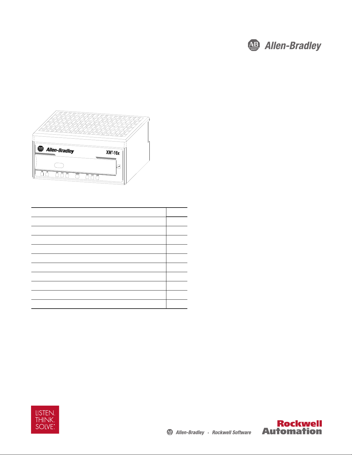
XM-160, XM-161, and XM-162 Direct Vibration Modules
Catalog Numbers
1440-VDRS06-00RH, 1440-VDRS06-06RH, 1440-VDRP06-00RH
Top ic Pa ge
Environment and Enclosure 3
European Hazardous Location Approval 4
North American Hazardous Location Approval 5
Mount the Module 6
Module Indicators 7
Self-Test 8
Reset Switch 8
Install the XM Serial Configuration Utilit y Software 9
Specifications 9
Additional Resources 11
Page 2
XM-160, XM-161, and XM-162 Direct Vibration Modules
IMPORTANT
Important User Information
Read this document and the documents listed in the additional resources section about installation, configuration, and
operation of this equipment before you install, configure, operate, or maintain this product. Users are required to
familiarize themselves with installation and wiring instructions in addition to requirements of all applicable codes, laws,
and standards.
Activities including installation, adjustments, putting into service, use, assembly, disassembly, and maintenance are required
to be carried out by suitably trained personnel in accordance with applicable code of practice.
If this equipment is used in a manner not specified by the manufacturer, the protection provided by the equipment may be
impaired.
In no event will Rockwell Automation, Inc. be responsible or liable for indirect or consequential damages resulting from the
use or application of this equipment.
The examples and diagrams in this manual are included solely for illustrative purposes. Because of the many variables and
requirements associated with any particular installation, Rockwell Automation, Inc. cannot assume responsibility or
liability for actual use based on the examples and diagrams.
No patent liability is assumed by Rockwell Automation, Inc. with respect to use of information, circuits, equipment, or
software described in this manual.
Reproduction of the contents of this manual, in whole or in part, without written permission of Rockwell Automation,
Inc., is prohibited.
Throughout this manual, when necessary, we use notes to make you aware of safety considerations.
WARNING: Identifies information about practices or circumstances that can cause an explosion in a hazardous
environment, which may lead to personal injury or death, property damage, or economic loss.
ATTENTION: Identifies information about practices or circumstances that can lead to personal injury or death, property
damage, or economic loss. Attentions help you identify a hazard, avoid a hazard, and recognize the consequence.
Identifies information that is critical for successful application and understanding of the product.
Labels may also be on or inside the equipment to provide specific precautions.
SHOCK HAZARD: Labels may be on or inside the equipment, for example, a drive or motor, to alert people that dangerous
voltage may be present.
BURN HAZARD: Labels may be on or inside the equipment, for example, a drive or motor, to alert people that surfaces may
reach dangerous temperatures.
ARC FLASH HAZARD: Labels may be on or inside the equipment, for example, a motor control center, to alert people to
potential Arc Flash. Arc Flash will cause severe injury or death. Wear proper Personal Protective Equipment (PPE). Follow
ALL Regulatory requirements for safe work practices and for Personal Protective Equipment (PPE).
2 Rockwell Automation Publication GMSI10-IN026C-EN-P - February 2014
Page 3
Environment and Enclosure
ATTENTION: This equipment is intended for use in a Pollution Degree 2 industrial environment, in overvoltage Category II
applications (as defined in IEC 60664-1), at altitudes up to 2000 m (6562 ft) without derating.
This equipment is not intended for use in residential environments and may not provide adequate protection to radio
communication services in such environments.
This equipment is supplied as open-type equipment. It must be mounted within an enclosure that is suitably designed for
those specific environmental conditions that will be present and appropriately designed to prevent personal injury resulting
from accessibility to live parts. The enclosure must have suitable flame-retardant properties to prevent or minimize the spread
of flame, complying with a flame spread rating of 5VA or be approved for the application if nonmetallic. The interior of the
enclosure must be accessible only by the use of a tool. Subsequent sections of this publication may contain additional
information regarding specific enclosure type ratings that are required to comply with certain product safety certifications.
In addition to this publication, see the following:
• Industrial Automation Wiring and Grounding Guidelines, publication 1770-4.1
• NEMA Standard 250 and IEC 60529, as applicable, for explanations of the degrees of protection provided by enclosures
XM-160, XM-161, and XM-162 Direct Vibration Modules
, for additional installation requirements
ATTENTION: To comply with UL/CSA restrictions and the CE Low Voltage Directive (LVD), all connections to this equipment must be
powered from a single source compliant with the following:
• A Listed Class 2 power supply, or a Listed ITE safety extra low voltage (SELV) power supply with the 1440-5AFUSEKIT fuse kit, or a
protected extra low voltage (PELV) power supply certified to 60950 with the 1440-5AFUSEKIT fuse kit.
• The same power source must power any device to which the module is connected via its side connector
circuits that include: power, XMbus, 4…20 mA outputs, and setpoint multiplier circuits.
(1) Power transmission across the XM module side connector must not exceed 3 A.
(2) These circuits are all functionally isolated, but do not have adequate insulation to satisfy the isolation requirements of some electrical safety
(2)
(1)
or any of its non-isolated
standards. Therefore the ground requirements for the circuits, specified in the individual user’s manuals, must still be applied.
Prevent Electrostatic Discharge
ATTENTION: This equipment is sensitive to electrostatic discharge, which can cause internal damage and affect normal
operation. Follow these guidelines when you handle this equipment:
• Touch a grounded object to discharge potential static.
• Wear an approved grounding wriststrap.
• Do not touch connectors or pins on component boards.
• Do not touch circuit components inside the equipment.
• Use a static-safe workstation, if available.
• Store the equipment in appropriate static-safe packaging when not in use.
Rockwell Automation Publication GMSI10-IN026C-EN-P - February 2014 3
Page 4
XM-160, XM-161, and XM-162 Direct Vibration Modules
ATTENTION: The serial communication port is intended for temporary local-programming purposes only and not intended
for permanent connection. The serial cable connections are not to exceed 3.0 m (9.84 ft):
• This product is intended to be mounted to a well-grounded mounting surface such as a metal panel or DIN rail. For DIN rail
mounting, use zinc plated yellow-chromate steel DIN rail to assure proper grounding. The use of other DIN rail materials
(for example, aluminum or plastic) that can corrode, oxidize, or are poor conductors, can result in improper or intermittent
grounding. Secure DIN rail to mounting surface approximately every 200 mm (7.8 in.) and use end-anchors appropriately.
• Do not remove or replace a terminal base unit while power is applied. Interruption of the backplane can result in
unintentional operation or machine motion.
• This module is designed so you can remove and insert it under power. However, when you remove or insert the module
with power applied, I/O attached to the module can change states due to its input/output signal changing conditions. Take
special care when using this feature.
European Hazardous Location Approval
This equipment is intended for use in potentially explosive atmospheres as defined by European Union Directive 94/9/EC and has been found to
comply with the Essential Health and Safety Requirements relating to the design and construction of Category 3 equipment intended for use in
Zone 2 potentially explosive atmospheres, given in Annex II to this Directive.
Compliance with the Essential Health and Safety Requirements has been assured by compliance with EN 60079-0, EN 60079-15 and EN 60079-11.
WARNING: The installation of the XM-16X module includes the following warnings:
• This equipment must be mounted in an ATEX-certified enclosure with a minimum ingress protection rating of at least IP54 (as
defined in IEC60529), and used in an environment of not more than Pollution Degree 2 (as defined in IEC 60664-1) when applied in
Zone 2 environments. The enclosure must have a tool-removable cover or door.
• This equipment must be used within its specified ratings defined by Rockwell Automation.
• Provision must be made to prevent the rated voltage from being exceeded by transient disturbances of more than 140% of the
rated voltage when applied in Zone 2 environments.
• This equipment must be used only with ATEX-certified Allen-Bradley terminal base units.
• Secure any external connections that mate to this equipment by using screws, sliding latches, threaded connectors, or other
means provided with this product.
• Do not disconnect equipment unless power has been removed or the area is known to be nonhazardous.
• Connection of the modules to barriers and/or sensors located in dangerous areas is the responsibility of the user.
• XM-160, XM-161, and XM-162 modules must be installed in accordance with specification control sheets 51263-HAZ and
51264-HAZ.
4 Rockwell Automation Publication GMSI10-IN026C-EN-P - February 2014
Page 5

North American Hazardous Location Approval
The following information applies when operating this equipment in
hazardous locations.
Products marked "CL I, DIV 2, GP A, B, C, D" are suitable for use in Class I Division 2
Groups A, B, C, D, Hazardous Locations and nonhazardous locations only. Each product is
supplied with markings on the rating nameplate indicating the hazardous location
temperature code. When combining products within a system, the most adverse
temperature code (lowest "T" number) may be used to help determine the overall
temperature code of the system. Combinations of equipment in your system are subject
to investigation by the local Authority Having Jurisdiction at the time of installation
EXPLOSION HAZARD -
• Do not disconnect equipment unless power has been
removed or the area is known to be nonhazardous.
• Do not disconnect connections to this equipment
unless power has been removed or the area is known to
be nonhazardous. Secure any external connections that
mate to this equipment by using screws, sliding
latches, threaded connectors, or other means provided
with this product.
• Substitution of components may impair suitability for
Class I, Division 2.
• If this product contains batteries, they must only be
changed in an area known to be nonhazardous.
Informations sur l'utilisation de cet équipement en environnements dangereux.
Les produits marqués "CL I, DIV 2, GP A, B, C, D" ne conviennent qu'à une utilisation en
environnements de Classe I Division 2 Groupes A, B, C, D dangereux et non dangereux.
Chaque produit est livré avec des marquages sur sa plaque d'identification qui indiquent le
code de température pour les environnements dangereux. Lorsque plusieurs produits sont
combinés dans un système, le code de température le plus défavorable (code de
température le plus faible) peut être utilisé pour déterminer le code de température global
du système. Les combinaisons d'équipements dans le système sont sujettes à inspection
par les autorités locales qualif iées au moment de l'installation.
XM-160, XM-161, and XM-162 Direct Vibration Modules
RISQUE D’EXPLOSION –
• Couper le courant ou s'assurer que l'environnement
est classé non dangereux avant de débrancher
l'équipement.
• Couper le courant ou s'assurer que l'environnement
est classé non dangereux avant de débrancher les
connecteurs. Fixer tous les connecteurs externes
reliés à cet équipement à l'aide de vis, loquets
coulissants, connecteurs filetés ou autres moyens
fournis avec ce produit.
• La substitution de composants peut rendre cet
équipement inadapté à une utilisation en
environnement de Classe I, Division 2.
• S'assurer que l'environnement est classé non
dangereux avant de changer les piles.
WARNING: The installation of the XM-16x module includes the following warnings:
• When you insert or remove the module while power is on, an electrical arc can occur. This could cause an explosion in
hazardous location installations. Be sure that power is removed or the area is nonhazardous before proceeding.
• If you connect or disconnect the serial cable with power applied to the module or the serial device on the other end of the
cable, an electrical arc can occur. This could cause an explosion in hazardous location installations. Be sure that power is
removed or the area is nonhazardous before proceeding.
• Be sure that power is removed or the area is nonhazardous before proceeding.
• If you connect or disconnect the XMbus cable with power applied to this module or any device on the network, an electrical
arc can occur. This could cause an explosion in hazardous location installations. Be sure that power is removed or the area is
nonhazardous before proceeding.
• If you connect or disconnect wiring while the field-side power is on, an electrical arc can occur. This could cause an
explosion in hazardous location installations. Be sure that power is removed or the area is nonhazardous before
proceeding.
• When you press the reset button while power is on, an electrical arc can occur. This could cause an explosion in hazardous
location installations. Be sure that power is removed or the area is nonhazardous before proceeding.
• Wiring to or from XM-160, XM-161, and XM-162 modules, which enters or leaves the system enclosure, must utilize wiring
methods suitable for Class I, Division 2 Hazardous Locations, as appropriate for the installation in accordance with the
following product drawings:
- Without Barriers - 51263-HAZ
- With Barriers - 51264-HAZ
Rockwell Automation Publication GMSI10-IN026C-EN-P - February 2014 5
Page 6

XM-160, XM-161, and XM-162 Direct Vibration Modules
Mount the Module
The module mounts on a XM® 947 terminal base unit, catalog number 1440-TB-H. We recommend that you mount the
modules after connecting the wiring on the terminal base unit. Refer to the XM-947 Direct Vibration Terminal Base
Installation Instructions, publication GMSI10-IN027
User Guide, publication GMSI10-UM025
ATTENTION: The XM-16X modules are compatible only with the XM-947 terminal base unit. Verify that the keyswitch on the
terminal base unit is at position 7 for the modules.
Do not attempt to install the XM-16X modules on other terminal base units or change the position of the
keyswitch after wiring the XM-947 terminal base unit.
1. Make certain the keyswitch (A) on the terminal base unit (C) is at position 7 as required for the modules.
, for wiring information.
, or the XM-160, XM-161, and XM-162 Direct Vibration Module
2. Make certain the side connector (B) is pushed all the way to the left.
You cannot install the module unless the connector is fully extended.
3. Make sure that the pins on the bottom of the module are straight so they align properly with the connector in the
terminal base unit.
4. Position the module (D) with its alignment bar (E) aligned with the groove (F) on the terminal base unit.
5. Press firmly and evenly to seat the module in the terminal base unit.
The module is seated when the latching mechanism (G) is locked into the module.
6. Repeat the above steps to install the next module in its terminal base unit.
All grounds in the system must be tied to the same point of the same grounding electrode system.
Maintain a 2.54 cm (1 in.) minimum clearance between the module and adjacent equipment. There are no orientation
restrictions.
6 Rockwell Automation Publication GMSI10-IN026C-EN-P - February 2014
Page 7

XM-160, XM-161, and XM-162 Direct Vibration Modules
1440-VDRx06-0xRH
Module Indicators
Module Indicators
Each module has eight status indicators, which are on top of the module.
Module Status (MS) Indicator
Color State Description
No color Off No power applied to the module.
Green Flashing Red Module performing power-up self-test.
Flashing Module operating in Program mode.
Solid Module operating in Run mode.
Red Flashing • Application firmware is invalid or not loaded. Download firmware to the module.
• Firmware download is currently in progress.
• The module power voltage is incorrect
Solid An unrecoverable fault has occurred. It is possible that the module must be repaired or replaced.
(1)
(2)
(1) Program mode - Typically this occurs when the module configuration settings are being updated with the Serial Configuration Utility. In Program mode, the module does not perform its normal functions.
The signal processing/measurement process is stopped, and the status of the alarms is set to the disarm state to prevent a false alert or danger status.
(2) Run mode - In Run mode, the module collects measurement data and monitors each measurement device.
Network Status (NS) Indicator
Color State Description
No color Off Module is not online:
• Module is autobauding.
• No power applied to the module; look at Module Status indicator.
Green Flashing Module is online (DeviceNet network) but no connections are currently established.
Solid Module is online with connections currently established.
Red Flashing One or more I/O connections are in the timed-out-state.
Solid Failed communication (duplicate MAC ID or bus-off).
(1) Normal condition when the module is not a slave to an XM-16x module, programmable controller, or other master device.
(1)
Rockwell Automation Publication GMSI10-IN026C-EN-P - February 2014 7
Page 8

XM-160, XM-161, and XM-162 Direct Vibration Modules
IMPORTANT
1440-VDRx06-0xRH
Reset Switch
Channel Status Indicator (six in all)
Color State Description
No color Off • Normal operation with alarm limits on the channel.
• No power applied to the module; look at Module Status indicator.
Yellow Solid An alert level alarm condition exists on the channel (and no transducer fault or danger level alarm condition exists).
Red Solid A danger level alarm condition exists on the channel (and no transducer fault condition exists).
Flashing A transducer fault condition exists on the channel.
Self-Test
The XM-16X modules perform a self-test at powerup. The self-test includes a status indicator test and a device test. During
the status indicator test, the indicators are turned on independently and in sequence for approximately 0.25 seconds.
The device test occurs after the status indicator test. The Module Status (MS) indicator is used to indicate the status of the
device self-test.
MS Indicator State Description
Flashing red and green Device self-test is in progress.
Solid green or flashing green Device self-test completed successfully, and the firmware is valid and running.
Flashing red • Device self-test completed, the hardware is OK, but the firmware is invalid.
Solid red Unrecoverable fault, hardware failure, or Boot Loader program corruption.
• The firmware download is in progress.
Reset Switch
The XM-16X modules have an external reset switch on top of the module. The Reset switch can be used to reset all latched
relays in the Relay Expansion module when it is attached to an XM-16X module.
The Reset switch resets the relays only if the input is no longer in alarm or the condition that caused the alarm is no longer
present.
8 Rockwell Automation Publication GMSI10-IN026C-EN-P - February 2014
Page 9

XM-160, XM-161, and XM-162 Direct Vibration Modules
Install the XM Serial Configuration Utility Software
The XM Documentation and Configuration Utility CD is packaged with the XM modules. It contains the XM Serial
Configuration Utility software, a set of user guides, hazardous location installation drawings, and electronic data sheet
(EDS) files that are used by network configuration tools such as RSNetWorx™ for DeviceNet software. The user guides are
in portable document format (PDF), and must be viewed with Adobe Acrobat Reader software.
To install the XM Serial Configuration Utility software, follow these steps.
1. Insert the XM Documentation and Configuration Utility CD-ROM into the CD-ROM drive.
If autorun is Then
Enabled The Setup program starts automatically and the XM Serial Configuration Utility opening screen appears.
Disabled Follow these steps.
1. Click Start, and then click Run.
The Run dialog box appears.
2. In the Open box, type x:\autorun, where x is the letter of the drive containing the XM Documentation and
Configuration Utility CD-ROM.
3. Click OK.
The XM Serial Configuration Utility opening screen appears.
2. Follow the instructions that appear to install the XM Serial Configuration Utility.
3. When you are finished installing the software, remove the XM Documentation and Configuration Utility
CD-ROM from the CD-ROM drives; store it in a safe place.
Specifications
The following table lists the technical specifications for the XM-16X modules.
Attribute XM-16X
Temperature, operating
IEC 60068-2-1 (Test Ad, Operating Cold),
IEC 60068-2-2 (Test Bd, Operating Dry Heat),
IEC 60068-2-14 (Test Nb, Operating Thermal Shock)
Temperature, surrounding air, max 65 °C (149 °F)
Temperature, nonoperating
IEC 60068-2-1 (Test Ab, Unpackaged Nonoperating Cold),
IEC 60068-2-2 (Test Bb, Unpackaged Nonoperating Dry Heat),
IEC 60068-2-14 (Test Na, Unpackaged Nonoperating Thermal Shock)
Relative humidity
IEC 60068-2-30 (Test Db, Unpackaged Damp Heat)
Vibration
IEC 60068-2-6 (Test Fc, Operating)
Shock, operating
IEC 60068-2-27 (Test Ea, Unpackaged Shock)
Shock, nonoperating
IEC 60068-2-27 (Test Ea, Unpackaged Shock)
-20…65 °C (-4…149 °F)
-40…85 °C (-40…185 °F)
5…95% noncondensing
2 g @ 10…500 Hz
15 g
20 g
Rockwell Automation Publication GMSI10-IN026C-EN-P - February 2014 9
Page 10

XM-160, XM-161, and XM-162 Direct Vibration Modules
Attribute XM-16X
Emissions
Class A
CISPR 11 (IEC 61000-6-4)
ESD immunity
8 kV air discharges
IEC 61000-4-2
Radiated RF immunity
IEC 61000-4-3
10V/m with 1 kHz sine-wave 80% AM from 80…2000 MHz
10V/m with 200 Hz 50% Pulse 100% AM at 900 MHz
10V/m with 200 Hz 50% Pulse 100% AM at 1890 MHz
3V/m with 1 kHz sine-wave 80% AM from 2000…2700 MHz
EFT/B immunity
IEC 61000-4-4
±2 kV at 5 kHz on shielded power ports
±2 kV at 5 kHz on shielded signal ports
±2 kV at 5 kHz on XMbus port
Surge transient immunity
IEC 61000-4-5
±2 kV line-earth(CM) on shielded power ports
±2kV line-earth(CM) on shielded signal ports
±2kV line-earth(CM) on XMbus port
Conducted RF immunity
10V rms with 1 kHz sine-wave 80% AM from 150 kHz…80 MHz
IEC 61000-4-6
Enclosure type rating None (open-style)
Voltagesranges XM-160/XM-162 Supply:
24V DC, 0.19 A
XM-161 Supply:
24V DC, 0.31 A
Power dissipation XM160/XM-162: 4.6 W @ 24V DC (4.3 W @ 18V DC, 4.9 W @ 32V DC), Class 2/SELV
XM-161: 7.4 W @ 24V DC (7 W @ 18V DC, 8 W @ 32V DC), Class 2/SELV
External over-current protection 440-5AFUSEKIT for SELV/PELV power source
Isolation voltage Not rated
Wiring categor y
(1)
2 - on shielded power and shielded signal ports
3 - on Serial ports
2 - on XMbus ports
Wire type Power and signal connections: shielded
North American temp code T4
IEC temp code T4
(1) Use this Conductor Category information for planning conductor routing. Refer to Industrial Automation Wiring and Grounding Guidelines, publication 1770-4.1.
10 Rockwell Automation Publication GMSI10-IN026C-EN-P - February 2014
Page 11

Certifications
XM-160, XM-161, and XM-162 Direct Vibration Modules
Certification
(when product is marked)
c-CSA-us CSA Certified Process Control Equipment for Class I, Division 2 Group A,B,C,D Hazardous Locations, certified for US and Canada. See CSA File 150115.
CE European Union 2004/108/EC EMC Directive, compliant with:
C-Tick Australian Radiocommunications Act, compliant with AS/NZS CISPR 11; Industrial Emissions
Ex European Union 94/9/EC ATEX Directive, compliant with:
KC Korean Registration of Broadcasting and Communications Equipment, compliant with Article 58-2 of Radio Waves Act, Clause 3
(1) See the Product Certification link at http://www.rockwellautomation.com for Declarations of Conformity, Certificates, and other certification details.
(1)
Description
• EN 61326-1; Meas./Control/Lab., Industrial Requirements
• EN 61000-6-2; Industrial Immunity
• EN 61000-6-4; Industrial Emissions
• EN 61131-2; Programmable Controllers (Clause 8, Zone A & B)
• EN 60079-15; Potentially Explosive Atmospheres, Protection "n"
• EN 60079-11; Explosive Atmospheres, Protection "i"
• EN 60079-0; General Requirements
• II 3 G Ex nAC [ic] IIC T4X Gc
Additional Resources
For more information on the products described in this publication, use these resources.
Resource Description
1440 XM Monitoring Modules Specifications Technical Data, publication 1440-TD001
XM-160/161/162 Direct Vibration Module User Guide, publication GMSI10-UM025 Provides information about how to install and configure the XM-160, XM-161, and
You can view or download Rockwell Automation publications at http:/www.rockwellautomation.com/literature/
Provides technical specifications for the 1440 series of monitoring modules.
XM-162 direct vibration module, along with technical specifications and DeviceNet
information and objects for the module.
. To
order paper copies of technical documentation, contact your local Allen-Bradley distributor or Rockwell Automation sales
representative.
Rockwell Automation Publication GMSI10-IN026C-EN-P - February 2014 11
Page 12

Rockwell Automation Support
Rockwell Otomasyon Ticaret A.Ş., Kar Plaza İş Merkezi E Blok Kat:6 34752 İçerenköy, İstanbul, Tel: +90 (216) 5698400
Rockwell Automation provides technical information on the Web to assist you in using its products.
At http://www.rockwellautomation.com/support
software service packs. You can also visit our Support Center at https://rockwellautomation.custhelp.com/
updates, support chats and forums, technical information, FAQs, and to sign up for product notification updates.
In addition, we offer multiple support programs for installation, configuration, and troubleshooting. For more
information, contact your local distributor or Rockwell Automation representative, or visit
http://www.rockwellautomation.com/services/online-phone
Installation Assistance
If you experience a problem within the first 24 hours of installation, review the information that is contained in this
manual. You can contact Customer Support for initial help in getting your product up and running.
United States or Canada 1.440.646.3434
Outside United States or Canada Use the Wor ldwi de Lo cato r
Rockwell Automation representative.
at http://www.rockwellautomation.com/rockwellautomation/support/overview.page, or contact your local
New Product Satisfaction Return
you can find technical and application notes, sample code, and links to
for software
.
Rockwell Automation tests all of its products to help ensure that they are fully operational when shipped from the
manufacturing facility. However, if your product is not functioning and needs to be returned, follow these procedures.
United States Contact your distributor. You must provide a Customer Support case number (call the phone number above to obtain one) to your
Outside United States Please contact your local Rockwell Automation representative for the return procedure.
distributor to complete the return process.
Documentation Feedback
Your comments will help us serve your documentation needs better. If you have any suggestions on how to improve this
document, complete this form, publication RA-DU002
Allen-Bradley, Rockwell Software, Rockwell Automation, XM, RSNetWor x, and LISTEN.THINK.SOLVE. are trademarks of Rockwell Automation, Inc.
Trademarks not belonging to Rockwell Automation are property of their respective companies.
, available at http://www.rockwellautomation.com/literature/.
Publication GMSI10-IN026C-EN-P - February 2014 PN-210607
Supersedes Publication GMSI10-IN026B-EN-E - October 2012 Copyright © 2014 Rockwell Auto mation, Inc. All rights reserved. Pr inted in the U.S.A.
 Loading...