

Page 1
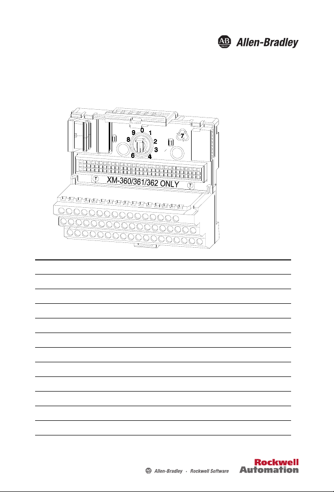
XM-944 Process/Temperature
Terminal Base
Catalog Number 1440-TB-E
Installation Instructions
For information about See page
Important User Information 2
Safety Approvals 4
Power Requirements 6
Interconnect Limit 7
Wiring Requirements 8
RTD Wiring Considerations 8
Grounding Requirements 9
Mounting on the DIN Rail 13
Wiring 16
Agency Certification 22
Specifications 23
Page 2
2 XM-944 Process/Temperature Terminal Base
WARNING
IMPORTANT
ATTENTION
SHOCK HAZARD
BURN HAZARD
Important User Information
Solid state equipment has operational characteristics differing from those of electromechanical
equipment. Safety Guidelines for the Application, Installation and Maintenance of Solid State Controls
(Publication SGI-1.1 available from your local Rockwell Automation sales office or online at
http://literature.rockwellautomation.com
equipment and hard-wired electromechanical devices. Because of this difference, and also because of
the wide variety of uses for solid state equipment, all persons responsible for applying this equipment
must satisfy themselves that each intended application of this equipment is acceptable.
In no event will Rockwell Automation, Inc. be responsible or liable for indirect or consequential damages
resulting from the use or application of this equipment.
The examples and diagrams in this manual are included solely for illustrative purposes. Because of the
many variables and requirements associated with any particular installation, Rockwell Automation, Inc.
cannot assume responsibility or liability for actual use based on the examples and diagrams.
No patent liability is assumed by Rockwell Automation, Inc. with respect to use of information, circuits,
equipment, or software described in this manual.
Reproduction of the contents of this manual, in whole or in part, without written permission of Rockwell
Automation, Inc., is prohibited.
Throughout this manual, when necessary, we use notes to make you aware of safety considerations.
Identifies information about practices or circumstances that can cause an explosion in
a hazardous environment, which may lead to personal injury or death, property
damage, or economic loss.
Identifies information that is critical for successful application and understanding of
the product.
) describes some important differences between solid state
Publication GMSI10-IN024A-EN-P - May 2010
Identifies information about practices or circumstances that can lead to personal
injury or death, property damage, or economic loss. Attentions help you identify a
hazard, avoid a hazard and recognize the consequences.
Labels may be on or inside the equipment (for example, drive or motor) to alert people
that dangerous voltage may be present.
Labels may be on or inside the equipment (for example, drive or motor) to alert people
that surfaces may reach dangerous temperatures.
Page 3
XM-944 Process/Temperature Terminal Base 3
ATTENTION
ATTENTION
Environment and Enclosure
This equipment is supplied as “open type” equipment. It must be mounted
within an enclosure that is suitably designed for those specific environmental
conditions that will be present, and appropriately designed to prevent persona l
injury resulting from accessibility to live parts. The interior of the enclosure
must be accessible only by the use of a tool. Subsequent sections of this
publication may contain additional information regarding specific enclosure
type ratings that are required to comply with certain product safety
certifications.
See NEMA Standards publication 250 and IEC publication 60529, as
applicable, for explanations of the degrees of protection provided by different
types of enclosures.
Preventing Electrostatic Discharge
This equipment is sensitive to electrostatic discharge, which can cause
internal damage and affect normal operation. Follow these guidelines when
you handle this equipment:
• Touch a grounded object to discharge potential static.
• Wear an approved grounding wriststrap.
• Do not touch connectors or pins on component boards.
• Do not touch circuit components inside the equipment.
• If available, use a static-safe workstation.
• When not in use, keep modules in appropriate static-safe packaging.
Publication
GMSI10-IN024A-EN-P - May 2010
Page 4
4 XM-944 Process/Temperature Terminal Base
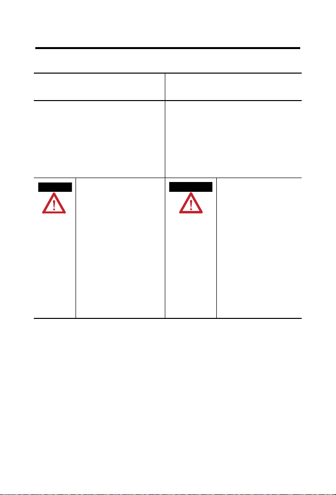
WARNING
AVERTISSEMENT
Safety Approvals
The following information applies when
operating this equipment in hazardous
locations.
Products marked "CL I, DIV 2, GP A, B, C, D" are suitable for
use in Class I Division 2 Groups A, B, C, D, Hazardous
Locations and nonhazardous locations only. Each product is
supplied with markings on the rating na meplate indicating
the hazardous location temperature code. When
combining products within a system, the most adverse
temperature code (lowest "T" number) m ay be used to help
determine the overall temperature code of the system.
Combinations of equipment in your system are subject to
investigation by the local Authorit y Having Jurisdiction at
the time of installation.
EXPLOSION HAZARD -
• Do not disconnect eq uipment unless
power has been removed or the
area is known to be nonhazardous.
• Do not disconnect connections to
this equipment unless power has
been removed or the area is known
to be nonhazardous. Secure any
external connections that mate to
this equipment by using screws,
sliding latches, threaded
connectors, or other means
provided with this product.
• Substitution of components may
impair suitability for Class I,
Division 2.
• If this product contains batteries,
they must only be changed in an
area known to be nonhazardous.
Informations sur l’utilisation de cet
équipement en environnements dangereux.
Les produits marqués "CL I, DIV 2, GP A, B, C, D" ne
conviennent qu'à une utilisation en environnements de
Classe I Division 2 Groupes A, B, C, D dangereux et non
dangereux. Chaque produit est livré avec des marqua ges sur
sa plaque d'identification qui indiquent le code de
température pour les environnement s dangereux. Lorsque
plusieurs produits sont combinés dans un système, le code de
température le plus défavorable (co de de température le plus
faible) peut être utilisé pour déterminer le code de
température global du système. Les comb inaisons
d'équipements dans le système sont sujettes à inspection pa r
les autorités locales qualifiées au moment de l'installation.
RISQUE D’EXPLOSION –
• Couper le courant ou s'assurer
que l'environnement est classé
non dangereux avant de
débrancher l'équipement.
• Couper le courant ou s'assurer
que l'environnement est classé
non dangereux avant de
débrancher les connecteurs. Fixer
tous les connecteurs externes
reliés à cet équipement à l'aide
de vis, loquets coulissants,
connecteurs filetés ou autres
moyens fournis avec ce produit.
• La substitution de composants
peut rendre cet équipement
inadapté à une utilisation en
environnement de Classe I,
Division 2.
• S'assurer que l'environnement est
classé non dangereux avant de
changer les piles.
Publication GMSI10-IN024A-EN-P - May 2010
Page 5
XM-944 Process/Temperature Terminal Base 5
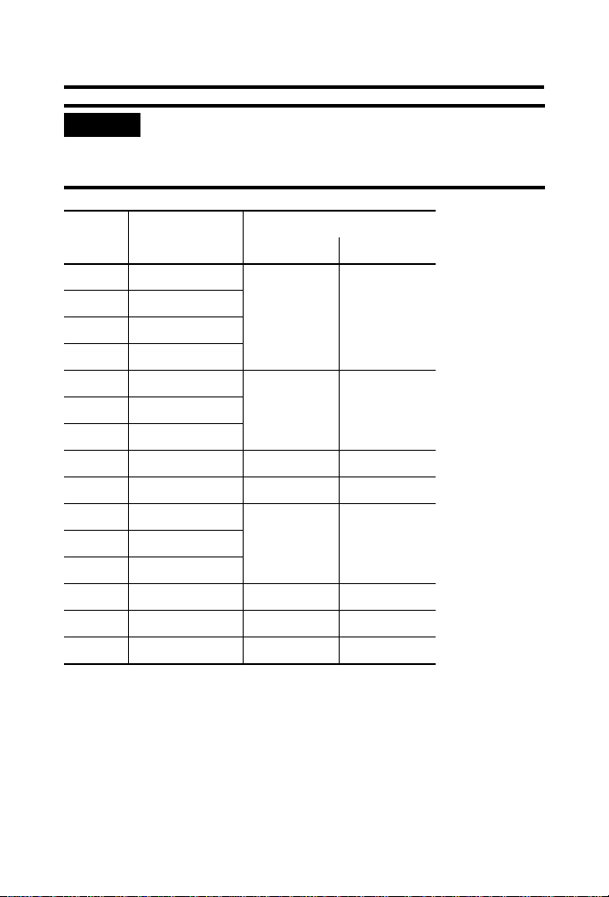
IMPORTANT
Wiring to or from this device, which enters or leaves the system enclosure,
must utilize wiring methods suitable for Class I, Division 2 Hazardous
Locations, as appropriate for the installation in accordance with the product
drawings as indicated in the following table.
Model Catalog Number Haz Location Drawings*
w/o Barriers w/ Barriers
XM-120 1440-VST0201RA
XM-121 1440-VLF0201RA
XM-122 1440-VSE0201RA
XM-123 1440-VAD0201RA
XM-160 1440-VDRS0600RH
XM-161 1440-VDRS0606RH
XM-162 1440-VDRP0600RH
XM-220 1440-SPD0201RB 48640-HAZ 48641-HAZ
XM-320 1440-TPS0201RB 48238-HAZ 48239-HAZ
XM-360 1440-TPR0600RE
XM-361 1440-TUN0600RE
XM-361 1440-TTC0600RE
XM-440 1440-RMA0004RC 48240-HAZ N/A
XM-441 1440-REX0004RD 48241-HAZ N/A
XM-442 1440-REX0304RG 48642-HAZ N/A
* Drawings are available on the included CD
48178-HAZ 48179-HAZ
51263-HAZ 51264-HAZ
48295-HAZ 48299-HAZ
Publication
GMSI10-IN024A-EN-P - May 2010
Page 6

6 XM-944 Process/Temperature Terminal Base
IMPORTANT
European Zone 2 Certification
If appropriately marked, this equipment is intended for use in potentially explosive
atmospheres as defined by European Union Directive 94/9/CE.
Compliance with the Essential Health and Safety Requirements has been assured by
compliance with EN 50021 (1999).
Observe the following additional Zone 2 certification requirements:
• This equipment is not resistant to sunlight or other sources of UV
radiation.
• The secondary of a current transformer shall not be open–circuited.
• The marking “ALCR” is to be considered “as applicable” to individual
products.
• Equipment of lesser Enclosure Type Rating must be installed in an
enclosure providing at least IP54 protection when applied in Class I,
Zone 2 environments.
• This equipment must be powered by energy limited associated
equipment as defined in EN 50021 when applied in Class I, Zone 2
environments.
• Provision shall be made to prevent the rated voltage from being
exceeded by transient disturbances of more than 40% when applied in
Class I, Zone 2 environments.
Power Requirements
Power Supply
Requires a 24Vdc (±10%) power source per the following table.
Publication GMSI10-IN024A-EN-P - May 2010
Page 7
XM-944 Process/Temperature Terminal Base 7
TIP
XM Power Supply Requirements
Listed Class 2 rated supply, or
Protection
Output Voltage 24Vdc ± 10%
Output Power 100 Watts Maximum (~4A @ 24Vdc)
Static Regulation ± 2%
Dynamic Regulation ± 3%
Ripple < 100mVpp
Output Noise Per EN50081-1
Overshoot < 3% at turn-on, < 2% at turn-off
Hold-up Time As required (typically 50mS at full rated load
* When a fused supply is used the fuse must be a 5 amp, listed, fast acting fuse such as
provided by Allen-Bradley part number 1440-5AFUSEKIT.
Fused* ITE Listed SELV supply, or
Fused* ITE Listed PELV supply
Refer to the specifications for the specific module for power consumption
and other requirements.
See XM Power Supply Solutions application technique, publication
ICM-AP005A-EN-E, for additional details.
Interconnect Limit
Total current draw through the side connector cannot exceed 3A. A separate
power connection is necessary if the total current draw of the interconnecting
modules is greater than 3A.
If the total current draw for a row of modules is greater than 3A, consider
connecting power to a module near the center of the rail, rather than at a
module on either end. Insure that there is less than 3A load in either direction
from the module where power is connected.
Publication
GMSI10-IN024A-EN-P - May 2010
Page 8
8 XM-944 Process/Temperature Terminal Base
ATTENTION
IMPORTANT
Wiring Requirements
Use solid or stranded wire. All XM wiring should meet the following
specifications:
• 14 to 22 AWG copper conductors without pretreatment; 8 AWG
required for grounding the DIN rail for electromagnetic interference
(emi) purposes
• Recommended strip length 8 millimeters (0.31 inches)
• Minimum insulation rating of 300V
• Soldering the conductor is forbidden
• Wire ferrules can be used with stranded conductors; copper ferrules
recommended
See the XM Documentation and Configuration Utility CD for Hazardous
Locations installation drawings. The XM Documentation and Configuration
Utility CD is packaged with the XM modules.
RTD Wiring Considerations
When using RTDs as inputs, give special consideration when selecting the
input cable. Select a cable that has consistent impedance throughout its entire
.
length
The XM-361 requires three wires to compensate for lead resistance error.
We recommend that you do not use 2-wire RTDs if long cable runs are
required, as it reduces the accuracy of the system. However, if a 2-wire
configuration is required, reduce the effect of the lead wire resistance by
using a lower-gauge wire for the cable (for example, use 16 AWG instead of
24 AWG).
When using a 3-wire configuration, the XM-361 compensates for resistance
error due to lead wire length. For example, in a 3-wire configuration, the
XM-361 reads the resistance due to the length of the wires and assumes that
the resistance of the other wire is equal. If the resistance of the individual lead
Publication GMSI10-IN024A-EN-P - May 2010
Page 9

XM-944 Process/Temperature Terminal Base 9
IMPORTANT
wires are much different, an error may exist. The closer the resistance values
are to each other, the greater the amount of error is eliminated.
To ensure temperature or resistance value accuracy, the
resistance difference of the cable lead wires must be equal to
or less than 0.01 ohm.
To ensure that the lead values match as closely as possible:
• Keep lead resistance as small as possible and less than 50 ohms.
• Use quality cable that has a small tolerance impedance rating.
• Use a heavy-gauge lead wire which has less resistance per foot.
Grounding Requirements
Use these grounding requirements to ensure safe electrical operating
circumstances, and to help avoid potential emi and ground noise that can
cause unfavorable operating conditions for your XM system.
DIN Rail Grounding
The XM modules make a chassis ground connection through the DIN rail.
The DIN rail must be connected to a ground bus or grounding electrode
conductor using 8 AWG or 1 inch copper braid. See illustration on the
following page.
Use zinc-plated, yellow-chromated steel DIN rail (Allen-Bradley part no.
199-DR1 or 199-DR4) or equivalent to assure proper grounding. Using other
DIN rail materials (e.g. aluminum, plastic, etc.), which can corrode, oxidize, or
are poor conductors can result in improper or intermittent platform
grounding.
Publication
GMSI10-IN024A-EN-P - May 2010
Page 10

10 XM-944 Process/Temperature Terminal Base
Power
Supply
DYNAMIC MEASUREMENT
1440-VST02-01RA
DYNAMIC MEASUREMENT
1440-VST02-01RA
POSITION
1440-TSP02-01RB
MASTER RELAY
1440-RMA00-04RC
EXPANSION RELAY
1440-REX00-04RD
EXPANSION RELAY
1440-REX00-04RD
EXPANSION RELAY
1440-REX00-04RD
EXPANSION RELAY
1440-REX00-04RD
Power
Supply
DYNAMIC MEASUREMENT
1440-VST02-01RA
DYNAMIC MEASUREMENT
1440-VST02-01RA
EXPANSION RELAY
1440-REX00-04RD
EXPANSION RELAY
1440-REX00-04RD
1
1
XM System DIN Rail Grounding
1 Use 14 AWG wire.
The grounding wire can be connected to the DIN rail using a DIN Rail
Grounding Block (see illustration below).
Publication GMSI10-IN024A-EN-P - May 2010
Page 11

XM-944 Process/Temperature Terminal Base 11
IMPORTANT
IMPORTANT
DIN Rail Grounding Block
24V Common Grounding
24V to the XM module must be grounded. When two or more power
supplies power the XM system, ground the 24 V Commons at a single point,
such as the ground bus bar.
If it is not possible or practical to ground the -24Vdc supply, then it is
possible for the system to be installed and operate ungrounded. However, if
installed ungrounded then the system must not be connected to a ground
through any other circuit unless that circuit is isolated externally.
Connecting a floating system to a non-isolated ground could result in
damage to the XM module(s) and/or any connected device. Also, operating
the system without a ground may result in the system not performing to the
published specifications regards measurement accuracy and
communications speed, distance or reliability.
The 24V Common and Signal Common terminals are internally connected.
They are isolated from the Chassis terminals unless they are connected to
ground as described in this manual. See Wiring on
assignments.
Publication
GMSI10-IN024A-EN-P - May 2010
page 16 for terminal
Page 12

12 XM-944 Process/Temperature Terminal Base
ATTENTION
To
Ground
Bus
Transducer Grounding
Make certain the transducers are electrically isolated from earth ground. Cable
shields must be grounded at one end of the cable, and the other end left
floating or not connected. It is recommended that where possible, the cable
shield be grounded at the XM terminal base (Chassis terminal) and not at the
transducer.
DeviceNet Grounding
The DeviceNet network is functionally isolated and must be referenced to
earth ground at a single point. XM modules can not be used with an external
DeviceNet power supply. Connect DeviceNet V- to earth ground at one of
the XM modules, as shown in the illustration below.
Grounded DeviceNet V- at XM Module
Use of a separate DeviceNet power supply is not permitted. See Application
Technique “XM Power Supply Solutions”, publication ICM-AP005A-EN-E, for
guidance in using XM with other DeviceNet products.
For more information on the DeviceNet installation, refer to the ODVA
Planning and Installation Manual - DeviceNet Cable System, which is
available on the ODVA web site (http://www.odva.org).
Publication GMSI10-IN024A-EN-P - May 2010
Page 13

XM-944 Process/Temperature Terminal Base 13
ATTENTION
Position terminal base at a slight angle and hook over the top of the DIN rail.
Mounting on the DIN Rail
You can also mount the terminal base to a grounded mounting plate. Refer to
the XM Module User Guide for details.
The XM-944 makes a chassis ground connection through the DIN rail. Use zinc
plated, yellow chromated steel DIN rail to assure proper grounding. Using
other DIN rail materials (e.g. aluminum, plastic, etc.) which can corrode,
oxidize or are poor conductors can result in improper or intermittent platform
grounding.
1. Position the terminal base unit on the 35 x 7.5mm DIN rail (A) (A-B
pt no. 199-DR1 or 199-DR4) at a slight angle.
2. Slide the terminal base unit over leaving room for the side
connector (B).
Publication
GMSI10-IN024A-EN-P - May 2010
Page 14

14 XM-944 Process/Temperature Terminal Base
IMPORTANT
3. Hook the lip on the rear of the terminal base onto the top of the DIN
rail, and rotate the terminal base onto the rail.
4. Press down on the ter minal base unit to lock the terminal base on the
DIN rail. If the terminal base does not lock into place, use a
screwdriver or similar device to open the locking tab, press down on
the terminal base until flush with the DIN rail and release the locking
tab to lock the base in place.
5. Connect the wiring for the XM-944 terminal base unit as shown
Wiring later in this document.
under
Interconnecting Terminal Base Units
Follow the steps below to install another terminal base unit.
Terminal base units are mounted left to right on the DIN rail.
1. Position the terminal base on the 35 x 7.5mm DIN rail (A).
2. Make certain the side connector (B) is fully retracted into the base
unit.
3. Slide the terminal base unit over tight against the neighboring terminal
base. Make sure the hook on the terminal base slides under the edge
of the terminal base unit.
Publication GMSI10-IN024A-EN-P - May 2010
Page 15

XM-944 Process/Temperature Terminal Base 15
4. Press down on the ter minal base unit to lock the terminal base on the
DIN rail. If the terminal base does not lock into place, use a
screwdriver or similar device to open the locking tab, press down on
the terminal base until flush with the DIN rail and release the locking
tab to lock the base in place.
5. Gently push the side connector into the side of the neighboring
terminal base to complete the backplane connection.
Publication
GMSI10-IN024A-EN-P - May 2010
Page 16

16 XM-944 Process/Temperature Terminal Base
IMPORTANT
WARNING
ATTENTION
Wiring
For more wiring connection information, refer to the XM
Module User Guide.
Terminal Assignments
EXPLOSION HAZARD
Do not disconnect equipment unless power has been removed
or the area is known to be nonhazardous.
Do not disconnect connections to this equipment unless power
has been removed or the area is known to be nonhazardous.
Secure any external connections that mate to this equipment by
using screws, sliding latches, threaded connectors, or other
means provided with this product.
The terminal block assignments are different for different
terminal base units. The following table applies only to the
XM-944. Refer to the installation instructions for the specific
terminal base unit for its terminal assignments.
Publication GMSI10-IN024A-EN-P - May 2010
Page 17

XM-944 Process/Temperature Terminal Base 17
XM-360 Process Module Terminal Assignments
No. Description No. Description
0 Chassis ground 26 Channel 4 V in (-) / Iin Sense
1 Chassis ground 27 Channel 5 V in (+) / Input in
2 Chassis ground 28 Channel 5 V in (-) / Iin Sense
3 Channel 1 input return 29 Channel 6 V in (+) / Input in
4 Channel 1 input return 30 Channel 6 V in (-) / Iin Sense
5 Channel 2 input return 31 Channel 4 4-20mA (+)
6 Channel 2 input return 32 Channel 5 4-20mA (+)
7 Channel 3 input return 33 Channel 6 4-20mA (+)
8 Channel 3 input return 34 Channel 1 4-20mA (-)
9 Channel 4 input return 35 Channel 2 4-20mA (-)
10 Channel 4 input return 36 Channel 3 4-20mA (-)
11 Channel 5 input return 37 24V in
12 Channel 5 input return 38 24V common
13 Channel 6 input return 39 Reserved
14 Channel 6 input return 40 No connection
15 Chassis ground 41 Chassis ground
16 Channel 1 4-20mA (+) 42 Chassis ground
17 Channel 2 4-20mA (+) 43 Chassis ground
18 Channel 3 4-20mA (+) 44 CAN_High (white wire)
19 Channel 1 V in (+) / Input in 45 CAN_Low (blue wire)
20 Channel 1 V in (-) / Iin Sense 46 CAN Shield (bare wire)
21 Channel 2 V in (+) / Input in 47 DeviceNet V (+) (red wire) (Optional,
see IMPORTANT note below)
22 Channel 2 V in (-) / Iin Sense 48 DeviceNet V (-) (black wire)
23 Channel 3 V in (+) / Input in 49 Channel 4 4-20mA (-)
Publication
GMSI10-IN024A-EN-P - May 2010
Page 18

18 XM-944 Process/Temperature Terminal Base
IMPORTANT
No. Description No. Description
24 Channel 3 V in (-) / Iin Sense 50 Channel 5 4-20mA (-)
25 Channel 4 V in (+) / Input in 51 Channel 6 4-20mA (-)
The DeviceNet power circuit through the XM module interconnect, whichis
rated at only 300mA, is not intended or designed to power DeviceNet loads.
Doing so could damage the module or terminal base.
To preclude this possibility, even unintentionally, it is recommended that
DeviceNet V+ be left unconnected.
Publication GMSI10-IN024A-EN-P - May 2010
Page 19

XM-944 Process/Temperature Terminal Base 19
XM-361 Temperature Module Terminal Assignments
No. Description No. Description
0 Chassis ground 26 Channel 4 TC (-) / RTD (-)
1 Chassis ground 27 Channel 5 TC (+) / RTD (-)
2 Chassis ground 28 Channel 5 TC (-) / RTD (-)
3 Channel 1 RTD (+) 29 Channel 6 TC (+) / RTD (-)
4 Channel 1 RTD (+) 30 Channel 6 TC (-) / RTD (-)
5 Channel 2 RTD (+) 31 Channel 4 4-20mA (+)
6 Channel 2 RTD (+) 32 Channel 5 4-20mA (+)
7 Channel 3 RTD (+) 33 Channel 6 4-20mA (+)
8 Channel 3 RTD (+) 34 Channel 1 4-20mA (-)
9 Channel 4 RTD (+) 35 Channel 2 4-20mA (-)
10 Channel 4 RTD (+) 36 Channel 3 4-20mA (-)
11 Channel 5 RTD (+) 37 24V in
12 Channel 5 RTD (+) 38 24V common
13 Channel 6 RTD (+) 39 Reserved
14 Channel 6 RTD (+) 40 No connection
15 Chassis ground 41 Chassis ground
16 Channel 1 4-20mA (+) 42 Chassis ground
17 Channel 2 4-20mA (+) 43 Chassis ground
18 Channel 3 4-20mA (+) 44 CAN_High (white wire)
19 Channel 1 TC (+) / RTD (-) 45 CAN_Low (blue wire)
20 Channel 1 TC (-) / RTD (-) 46 CAN Shield (bare wire)
21 Channel 2 TC (+) / RTD (-) 47 DeviceNet V (+) (red wire) (Optional,
see IMPORTANT note below)
22 Channel 2 TC (-) / RTD (-) 48 DeviceNet V (-) (black wire)
23 Channel 3 TC (+) / RTD (-) 49 Channel 4 4-20mA (-)
Publication
GMSI10-IN024A-EN-P - May 2010
Page 20

20 XM-944 Process/Temperature Terminal Base
IMPORTANT
No. Description No. Description
24 Channel 3 TC (-) / RTD (-) 50 Channel 5 4-20mA (-)
25 Channel 4 TC (+) / RTD (-) 51 Channel 6 4-20mA (-)
The DeviceNet power circuit through the XM module interconnect, whichis
rated at only 300mA, is not intended or designed to power DeviceNet loads.
Doing so could damage the module or terminal base.
To preclude this possibility, even unintentionally, it is recommended that
DeviceNet V+ be left unconnected.
Publication GMSI10-IN024A-EN-P - May 2010
Page 21

XM-944 Process/Temperature Terminal Base 21
XM-362 Isolated Thermocouple Temperature Module Terminal Assignments
No. Description No. Description
0 Chassis ground 26 Channel 4 TC (-)
1 Chassis ground 27 Channel 5 TC (+)
2 Chassis ground 28 Channel 5 TC (-)
3 No connection 29 Channel 6 TC (+)
4 No connection 30 Channel 6 TC (-)
5 No connection 31 Channel 4 4-20mA (+)
6 No connection 32 Channel 5 4-20mA (+)
7 No connection 33 Channel 6 4-20mA (+)
8 No connection 34 Channel 1 4-20mA (-)
9 No connection 35 Channel 2 4-20mA (-)
10 No connection 36 Channel 3 4-20mA (-)
11 No connection 37 24V in
12 No connection 38 24V common
13 No connection 39 Reserved
14 No connection 40 No connection
15 Chassis ground 41 Chassis ground
16 Channel 1 4-20mA (+) 42 Chassis ground
17 Channel 2 4-20mA (+) 43 Chassis ground
18 Channel 3 4-20mA (+) 44 CAN_High (white wire)
19 Channel 1 TC (+) 45 CAN_Low (blue wire)
20 Channel 1 TC (-) 46 CAN Shield (bare wire)
21 Channel 2 TC (+) 47 DeviceNet V (+) (red wire) (Optional,
see IMPORTANT note below)
22 Channel 2 TC (-) 48 DeviceNet V (-) (black wire)
23 Channel 3 TC (+) 49 Channel 4 4-20mA (-)
Publication
GMSI10-IN024A-EN-P - May 2010
Page 22

22 XM-944 Process/Temperature Terminal Base
IMPORTANT
No. Description No. Description
24 Channel 3 TC (-) 50 Channel 5 4-20mA (-)
25 Channel 4 TC (+) 51 Channel 6 4-20mA (-)
The DeviceNet power circuit through the XM module interconnect, whichis
rated at only 300mA, is not intended or designed to power DeviceNet loads.
Doing so could damage the module or terminal base.
To preclude this possibility, even unintentionally, it is recommended that
DeviceNet V+ be left unconnected.
Agency Certification (when product marked)
UL UL Listed for Ordinary Locations
UL UL Listed for Class I, Division 2 Group A, B, C, and D Hazardous Locations
CSA CSA Certified Process Control Equipment
CSA CSA Certified Process Control Equipment for Class I, Division 2 Group A, B, C,
and D Hazardous Locations
2
EEX
CE
C-Tick
European Union 94/9/EEC ATEX Directive, compliant with EN 50021; Potentially
Explosive Atmospheres, Protection “n”
2
European Union 89/336/EEC EMC Directive
2
Australian Radiocommunications Act, compliant with:
AS/NZS 2064, Industrial Emissions
2 See the Product Certification link at www.rockwellautomation.com for Declarations of Conformity,
Certificates and other certification details.
Publication GMSI10-IN024A-EN-P - May 2010
Page 23

XM-944 Process/Temperature Terminal Base 23
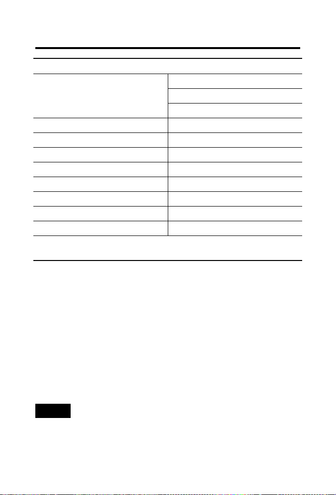
Specifications
The following table lists the technical specifications for the XM-944
Process/Temperature Terminal Base.
Product Feature Specification
Power
Module
+21.6 to +26.4V dc
Consumption
Heat Production
Environmental
Operating Temperature
Storage Temperature
Relative Humidity
Conformal Coating
Physical
Dimensions
Terminal Screw Torque
Maximum (XM-360): 300 mA
Typical (XM-360): 170mA
Maximum (XM-361, XM-362): 400mA
Maximum: 7.20 Watts (24.6 BTU/hr)
Typical: 4 Watts (14 BTU/hr)
-20 to +65°C (-4 to +149°F)
-40 to +85°C (-40 to +185°F)
95% non-condensing
All printed circuit boards are conformally coated in
accordance with IPC-A-610C.
3.875 W x 3.75 D x 2.25 H inches
9.48 W x 9.53 D x 5.72 H centimeters
7 pound-inches (0.6 Nm)
Note: Power specification is with module installed.
Publication
GMSI10-IN024A-EN-P - May 2010
Page 24

Rockwell Automation Support
Rockwell Automation provides technical information on the Web to assist you in using its products. At
http://www.rockwellautomation.com/support/
technical and application notes, sample code and links to software service packs, and a MySupport feature
that you can customize to make the best use of these tools.
For an additional level of technical phone support for installation, configuration, and troubleshooting, we
offer TechConnect support programs. For more information, contact your local distributor or Rockwell
Automation representative, or visit http://www.rockwellautomation.com/support/
Installation Assistance
If you experience a problem within the first 24 hours of installation, please review the information that's
contained in this manual. You can also contact a special Customer Support number for initial help in getting
your product up and running.
United States or Canada 1.440.646.3434
Outside United States or
Canada
Use the Worldwide Locator
http://www.rockwellautomation.com/support/americas/phone_en.html
contact your local Rockwell Automation representative.
New Product Satisfaction Return
Rockwell Automation tests all of its products to ensure that they are fully operational when shipped from
the manufacturing facility. However, if your product is not functioning and needs to be returned, follow
these procedures.
United States Contact your distributor. You must provide a Customer Support case number
Outside United States Please contact your local Rockwell Automation representative for the return
(call the phone number above to obtain one) to your distributor to complete
the return process.
procedure.
Documentation Feedback
Your comments will help us serve your documentation needs better. If you have any suggestions on how to
improve this document, complete this form, publication RA-DU002
http://literature.rockwellautomation.com
, you can find technical manuals, a knowledge base of FAQs,
.
at
.
, available at
, or
Allen-Bradley, Rockwell Software, Rockwell Automation, and XM are trademarks of Rockwell Automation, Inc.
Trademarks not belonging to Rockwell Automation are property of their respective companies.
Publication GMSI10-IN024A-EN-P - May 2010 PN-71170
Supersedes Publication GMSI10-UM024A-EN-E - January 2006 Copyright © 2010 Rockwell Automation, Inc. All rights reserved. Printed in the U.S.A.
 Loading...