

Page 1
Installation Instructions
XM ControlNet Adapter
Catalog Number 1440-ACNR
Topic Page
Important User Information 2
Environment and Enclosure 3
Prevent Electrostatic Discharge 4
North American Hazardous Location Approval 5
European Hazardous Location Approval 6
Before You Begin 7
XM Bus 8
Install the ControlNet Adapter 9
Product Dimensions 11
Wire the ControlNet Adapter 12
Set the Node Address 14
Install a Replacement ControlNet Adapter to an Existing System 15
Status Indicators 17
Specifications 19
Additional Resources 23
Page 2
2 XM ControlNet Adapter
WARNING
IMPORTANT
ATTENTION
SHOCK HAZARD
BURN HAZARD
Important User Information
Solid state equipment has operational characteristics differing from those of electromechanical
equipment. Safety Guidelines for the Application, Installation and Maintenance of Solid State Controls
(Publication SGI-1.1
http://www.rockwellautomation.com/literature
state equipment and hard-wired electromechanical devices. Because of this difference, and also because
of the wide variety of uses for solid state equipment, all persons responsible for applying this equipment
must satisfy themselves that each intended application of this equipment is acceptable.
In no event will Rockwell Automation, Inc. be responsible or liable for indirect or consequential damages
resulting from the use or application of this equipment.
The examples and diagrams in this manual are included solely for illustrative purposes. Because of the
many variables and requirements associated with any particular installation, Rockwell Automation, Inc.
cannot assume responsibility or liability for actual use based on the examples and diagrams.
No patent liability is assumed by Rockwell Automation, Inc. with respect to use of information, circuits,
equipment, or software described in this manual.
Reproduction of the contents of this manual, in whole or in part, without written permission of Rockwell
Automation, Inc., is prohibited.
Throughout this manual, when necessary, we use notes to make you aware of safety considerations.
available from your local Rockwell Automation sales office or online at
Identifies information about practices or circumstances that can cause an explosion in
a hazardous environment, which may lead to personal injury or death, property
damage, or economic loss.
Identifies information that is critical for successful application and understanding of
the product.
) describes some important differences between solid
Publication
Identifies information about practices or circumstances that can lead to personal
injury or death, property damage, or economic loss. Attentions help you identify a
hazard, avoid a hazard and recognize the consequences.
Labels may be on or inside the equipment (for example, drive or motor) to alert people
that dangerous voltage may be present.
Labels may be on or inside the equipment (for example, drive or motor) to alert people
that surfaces may reach dangerous temperatures.
ICM-IN001B-EN-P - March 2013
Page 3
Environment and Enclosure
ATTENTION
WARNING
This equipment is intended for use in a Pollution Degree 2 industrial
environment, in overvoltage Category II applications (as defined in IEC
publication 60664-1), at altitudes up to 2000 meters (6562 ft) without derating.
This equipment is not intended for use in residential environments and may not
provide adequate protection to radio communication services in such
environments.
This equipment is supplied as open-type equipment. It must be mounted within
an enclosure that is suitably designed for those specific environmental
conditions that will be present and appropriately designed to prevent personal
injury resulting from accessibility to live parts. The enclosure must have
suitable flame-retardant properties to prevent or minimize the spread of flame,
complying with a flame spread rating of 5VA or be approved for the application
if non-metallic. The interior of the enclosure must be accessible only by the use
of a tool. Subsequent sections of this publication may contain additional
information regarding specific enclosure type ratings that are required to
comply with certain product safety certifications.
In addition to this publication, see:
• Industrial Automation Wiring and Grounding Guidelines, for additional
installation requirements, publication 1770-4.1
• NEMA Standards publication 250 and IEC publication 60529, as
applicable, for explanations of the degrees of protection provided by
enclosures.
XM ControlNet Adapter 3
.
This equipment must be mounted in an ATEX certified enclosure with a
minimum ingress protection rating of at least IP54 (as defined in IEC60529) and
used in an environment of not more than Pollution Degree 2 (as defined in IEC
60664-1) when applied in Zone 2 environments. The enclosure must utilize a
tool removable cover or door.
Publication
ICM-IN001B-EN-P - March 2013
Page 4
4 XM ControlNet Adapter
ATTENTION
Prevent Electrostatic Discharge
This equipment is sensitive to electrostatic discharge, which can cause
internal damage and affect normal operation. Follow these guidelines when
you handle this equipment:
• Touch a grounded object to discharge potential static.
• Wear an approved grounding wrist strap.
• Do not touch connectors or pins on component boards.
• Do not touch circuit components inside the equipment.
• Use a static-safe workstation, if available.
• Store the equipment in appropriate static-safe packaging when not in
use.
Publication
ICM-IN001B-EN-P - March 2013
Page 5
North American Hazardous Location Approval
WARNING
AVERTISSEMENT
The following information applies when
operating this equipment in hazardous
locations:
Products marked "CL I, DIV 2, GP A, B, C, D" are suitable for
use in Class I Division 2 Groups A, B, C, D, Hazardous
Locations and nonhazardous locations only. Each product is
supplied with markings on the rating na meplate indicating
the hazardous location temperature code. When
combining products within a system, the most adverse
temperature code (lowest "T" number) m ay be used to help
determine the overall temperature code of the system.
Combinations of equipment in your system are subject to
investigation by the local Authority H aving Jurisdiction at
the time of installation.
EXPLOSION HAZARD
• Do not disconnect eq uipment unless
power has been removed or the
area is known to be nonhazardous.
• Do not disconnect connections to
this equipment unless power has
been removed or the area is known
to be nonhazardous. Secure any
external connections that mate to
this equipment by using screws,
sliding latches, threaded
connectors, or other means
provided with this product.
• Substitution of components may
impair suitability for Class I,
Division 2.
• If this product contains batteries,
they must only be changed in an
area known to be nonhazardous.
Informations sur l'utilisation de cet
équipement en environnements dangereux:
Les produits marqués "CL I, DIV 2, GP A, B, C, D" ne
conviennent qu'à une utilisation en environnements de
Classe I Division 2 Groupes A, B, C, D dangereux et non
dangereux. Chaque produit est livré avec des marqua ges sur
sa plaque d'identification qui indiquent le code de
température pour les environneme nts dangereux. Lorsque
plusieurs produits sont combinés dans un système, le code de
température le plus défavorable (co de de température le plus
faible) peut être utilisé pour déterminer le code de
température global du système. Les comb inaisons
d'équipements dans le système sont sujettes à inspection par
les autorités locales qualifiées au moment de l'installation.
XM ControlNet Adapter 5
RISQUE D’EXPLOSION
• Couper le courant ou s'assurer
que l'environnement est classé
non dangereux avant de
débrancher l'équipement.
• Couper le courant ou s'assurer
que l'environnement est classé
non dangereux avant de
débrancher les connecteurs. Fixer
tous les connecteurs externes
reliés à cet équipement à l'aide
de vis, loquets coulissants,
connecteurs filetés ou autres
moyens fournis avec ce produit.
• La substitution de composants
peut rendre cet équipement
inadapté à une utilisation en
environnement de Classe I,
Division 2.
• S'assurer que l'environnement est
classé non dangereux avant de
changer les piles.
Publication
ICM-IN001B-EN-P - March 2013
Page 6
6 XM ControlNet Adapter
ATTENTION
WARNING
European Hazardous Location Approval
The following applies when the product bears the Ex Marking.
This equipment is intended for use in potentially explosive atmospheres as defined by
European Union Directive 94/9/EC and has been found to comply with the Essential Health
and Safety Requirements relating to the design and construction of Category 3 equipment
intended for use in Zone 2 potentially explosive atmospheres, given in Annex II to this
Directive.
Compliance with the Essential Health and Safety Requirements has been assured by
compliance with EN 60079-15 and EN 60079-0.
This equipment is not resistant to sunlight or other sources of UV radiation.
• This equipment must be installed in an enclosure providing at least IP54
protection when applied in Zone 2 environments.
• This equipment must be used within its specified ratings defined by
Rockwell Automation.
• Provision must be made to prevent the rated voltage from being exceeded
by transient disturbances of more than 140% of the rated voltage when
applied in Zone 2 environments.
Publication
• This equipment must be used only with ATEX certified backplanes.
• Secure any external connections that mate to this equipment by using
screws, sliding latches, threaded connectors, or other means provided
with this product.
• Do not disconnect equipment unless power has been removed or the area
is known to be nonhazardous.
ICM-IN001B-EN-P - March 2013
Page 7
XM ControlNet Adapter 7
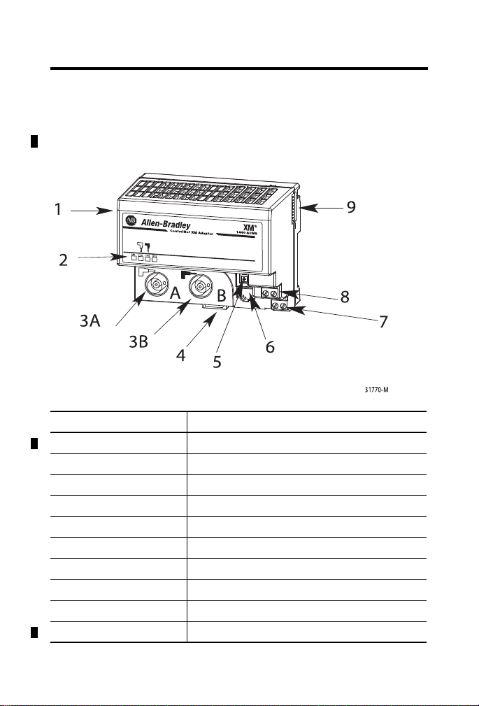
Before You Begin
The XM® ControlNet adapter is a communication adapter for the
1440-DYN02-01RJ module. It provides an interface for controlling this
module on an XM bus and transferring data to the processor over a
ControlNet network.
Component Description
1 ControlNet adapter module
2 Indicators
3A ControlNet network cable BNC connector A
3B ControlNet network cable BNC connector B
4 Module locking tab
5 ControlNet node selection pushwheel switches
6 ControlNet programming terminal connector port
7 24V DC connection
8 24V common connection
9 XM bus connector
Publication
ICM-IN001B-EN-P - March 2013
Page 8
8 XM ControlNet Adapter
ATTENTION
ATTENTION
ATTENTION
ATTENTION
Supply
XM
®
24 V
1
1
1
24 V COM
Class 2
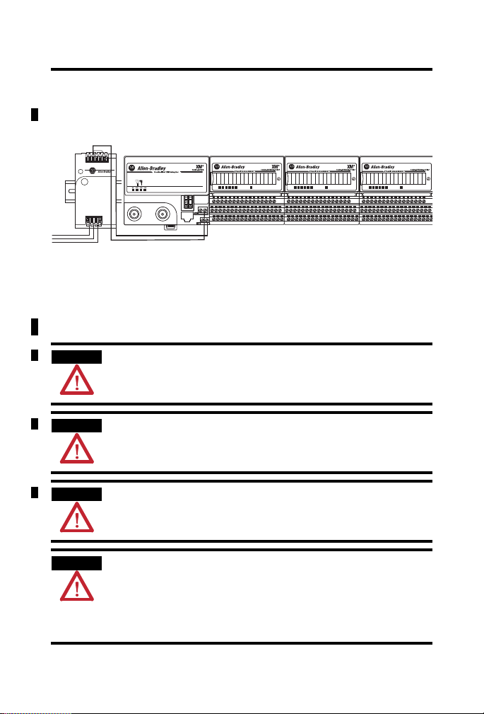
XM Bus
The XM bus connector, located on the side of the adapter, connects the
adapter to the XM modules on the DIN rail, as illustrated below.
The XM Bus connector passes power and XM network communications
between the connected modules. The XM network communicates using
standard DeviceNet protocols and CAN transceivers, but it does not share the
same specifications for the media (wire) and isolation characteristics.
The total current draw through the XM Bus connector cannot exceed 3 A.
Multiple power sources are not allowed.
Publication
Do not wire more than two conductors onto any single power terminal.
To comply with the CE Low Voltage Directive (LVD), all connections to this
equipment must be powered from a source compliant with the following:
Safety Extra Low Voltage (SELV) or Protected Extra Low Voltage (PELV).
To comply with UL restrictions, this equipment must be powered from a source
compliant with the following: Class 2.
ICM-IN001B-EN-P - March 2013
Page 9

XM ControlNet Adapter 9
ATTENTION
ATTENTION
IMPORTANT
IMPORTANT
Cont r olNet XM Adapter
1440-ACNR
XM
®
MS
CHA
CHB
BPS
A
B
Cont r olNet XM Adapter
1440-ACNR
XM
®
MS CHA CHB BPS
C
31769-M
Install the ControlNet Adapter
Do not remove or replace an adapter module while power is applied.
Interruption of the backplane can result in unintentional operation or machine
motion.
This product is grounded through the DIN rail to chassis ground. Use zinc
plated yellow-chromate steel DIN rail to assure proper grounding. The use of
other DIN rail materials (for example, aluminum or plastic) that can corrode,
oxidize, or are poor conductors, can result in improper or intermittent
grounding. Secure DIN rail to mounting surface approximately every 200 mm
(7.8 in.) and use end-anchors appropriately.
The 1440-DYN02-01RJ Standard Dynamic Measurement module is used
with the 1440-ACNR adapter. No other XM catalog number will work with
the 1440-ACNR adapter.
The XM bus must be terminated on each end with a 120 ohm, 1%, 1/4 W
resistor. Because the adapter has an internal terminator resistor, the second
resistor must be installed at the opposite end of the bus.
To install the adapter on the DIN rail prior to installing the XM terminal base
units, follow these steps.
1. Position the ControlNet adapter module (A) on a 35 x 7.5 mm DIN
rail (B) at a slight angle.
Publication
ICM-IN001B-EN-P - March 2013
Page 10

10 XM ControlNet Adapter
2. Hook the lip on the rear of the adapter onto the top of the DIN rail,
and rotate the adapter module onto the rail.
3. Press the adapter module down onto the DIN rail until flush. Locking
tab C will snap into position and lock the adapter module to the DIN
rail.
4. If the adapter module does not lock in place, use a screwdriver or
similar device to move the locking tab down while pressing the
adapter module flush onto the DIN rail, and release the locking tab to
lock the adapter module in place. If necessary, push up on the locking
tab to lock.
5. Connect the adapter wiring. Refer to
Wire the ControlNet Adapter on
page 12.
Panel/Wall Mounting
If mounting the adapter to a panel or wall, refer to publication 1794-5.13,
"Panel Mounting Kit, Cat. No. 1794-NM1."
Publication
ICM-IN001B-EN-P - March 2013
Page 11

XM ControlNet Adapter 11
ControlNet XM Adapter
2
5
1440-ACNR
AB
DIN Rail
Center of DIN Rail
Product Dimensions
Maintain at least 25.4 mm (1.0 in.) air space around your XM system
installation.
Publication
ICM-IN001B-EN-P - March 2013
Page 12

12 XM ControlNet Adapter
WARNING
WARNING
ATTENTION
Wire the ControlNet Adapter
If you connect or disconnect wiring while the field-side power is on, an
electrical arc can occur. This could cause an explosion in hazardous location
installations. Be sure that power is removed or the area is nonhazardous
before proceeding.
If you connect or disconnect the communication cable with power applied to
this module or any device on the network, an electrical arc can occur. This
could cause an explosion in hazardous location installations.
Be sure that power is removed or the area is nonhazardous before proceeding.
Do not wire more than two conductors onto any single terminal.
Publication
ICM-IN001B-EN-P - March 2013
Page 13

XM ControlNet Adapter 13
WARNING
ATTENTION
ControlNet XM Adapter
2
5
1440-ACNR
AB
A
BG
CE
DF
The NAP port is intended for temporary local programming purposes only and
not intended for permanent connection. If you connect or disconnect the NAP
cable with power applied to this module or any device on the network, an
electrical arc can occur. This could cause an explosion in hazardous location
installations.
Be sure that power is removed or the area is nonhazardous before proceeding.
1. Connect the ControlNet network cable to connector A.
2. Connect the redundant ControlNet network cable to connector B.
When connecting wiring, torque terminal screws C, D, E, and F to 0.8 N•m
(7 lb•in.).
3. Connect +V DC power to the lower connector, terminal F or D.
4. Connect -V common to the upper connector, terminal E or C.
Publication
ICM-IN001B-EN-P - March 2013
Page 14

14 XM ControlNet Adapter
2
5
Press either the + or
- buttons to change
the number.
Network
Address
Switches
Set the Node Address
Set the network address using the 2-button pushwheel switch (G). Valid
settings range are 01...99.
Publication
ICM-IN001B-EN-P - March 2013
Page 15

XM ControlNet Adapter 15
ATTENTION
ATTENTION
WARNING
WARNING
Install a Replacement ControlNet Adapter to an Existing System
If you insert or remove the module while backplane power is on, an electrical
arc can occur. This could cause an explosion in hazardous location
installations.
Be sure that power is removed or the area is nonhazardous before proceeding.
Do not remove or replace an adapter module while power is applied.
Interruption of the backplane can result in unintentional operation or machine
motion.
If you connect or disconnect wiring while the field-side power is on, an
electrical arc can occur. This could cause an explosion in hazardous location
installations. Be sure that power is removed or the area is nonhazardous
before proceeding.
If you connect or disconnect the communications cable with power applied to
this module or any device on the network, an electrical arc can occur. This
could cause an explosion in hazardous location installations.
Be sure that power is removed or the area is nonhazardous before proceeding.
Remove the existing adapter from the DIN rail as follows.
1. Disconnect any wiring jumpered to the adjacent terminal base.
2. Disconnect the BNC connector(s) from the front of the adapter.
3. On the XM module adjacent to the adapter, open the latching
mechanism and remove the module from the terminal base unit that is
attached to the adapter.
4. Push the XM bus connector toward the right side of the terminal base
to unplug the backplane connection.
5. Release the locking tab and remove the adapter module.
Publication
ICM-IN001B-EN-P - March 2013
Page 16

16 XM ControlNet Adapter
Cont r olNet XM Adapter
1440-ACNR
XM
®
M
S
CH
A CHBBPS
Install the replacement adapter on the DIN rail as follows.
1. Before installing the replacement adapter, make certain the XM Bus
connector of the terminal base is fully retracted into the base unit.
2. Position the replacement adapter on the DIN rail. The hook on the
terminal base slides under the edge of the adapter.
3. Push down and in at the same time to lock the adapter to the DIN
rail.
If the adapter does not lock in place, use a screwdriver or similar
device to move the locking tab down while pressing the adapter flush
onto the DIN rail, and release the locking tab to lock the adapter
module in place.
4. Gently push the XM bus connector into the side of the adapter to
complete the backplane.
5. Reinstall the XM module in the adjacent terminal base.
6. Connect the wiring to the adjacent terminal base.
7. Connect the ControlNet cable to the adapter.
Publication
ICM-IN001B-EN-P - March 2013
Page 17

ControlNet XM Adapter
2
5
1440-ACNR
AB
Channel A
Channel B
Module
Status
Back
Plane
Status
XM ControlNet Adapter 17
Status Indicators
Indicator State Description
Module Status Off No power applied to the device
Alternating Red/Green LED power up test (module self-test)
Flashing Red Recoverable fault has occurred:
• Firmware (NVS) update
• MAC ID changed
• CPU load exceeded
Solid Red Unrecoverable fault has occurred:
• Self test failure (checksum failure at
power up, RAM test failure at power
up
Solid Green Module is operating correctly (normal mode)
• Firmware fatal error
Publication
ICM-IN001B-EN-P - March 2013
Page 18

18 XM ControlNet Adapter
Indicator State Description
CH A and CH B
Viewed
Together
CH A and CH B
Viewed
Individually
Back Plane
Status
Both Off Reset, no power or entire network interface
deactivated
Alternating Red/Green Self test mode
Alternating Red/Off Bad/invalid node configuration (such as
duplicate MAC ID)
Both Red Failed link interface or failed module
Off Channel disabled or channel not supported
Flashing Red/Green Invalid link configuration
Flashing Red/Off Severe Link error - link fault or no MAC
frames received
Flashing Green/Off Temporary channel error or listen-only
Solid Green Normal operation - MAC frames are being
received without detected errors
Off Device not powered - check module status
indicator
Flashing Red Recoverable fault has occurred.
One or more connections have timed out.
Applies to ControlNet and XM Bus
connections.
Solid Red Unrecoverable fault has occurred:
• adapter is “bus off”
• adapter has failed its duplicate MAC
ID check
Flashing Green Adapter on-line with no connections
established
Solid Green Adapter on-line with connections
established (normal operation, in run mode)
Publication
ICM-IN001B-EN-P - March 2013
Page 19

XM ControlNet Adapter 19
Specifications
XM ControlNet Adapter - 1440-ACNR
Attribute Value
Enclosure Type Rating None (open-style)
Input Voltage 24V DC
XM Bus Output 24V DC, 3 A Max
Isolation Voltage 50V (continuous), Basic Insulation Type
Wire Size Power connections:
Wiring Category
(1)
Terminal Block Torque 0.8 N•m (7 lb•in.)
North American Temp Code T4A
IEC Temp Code T4
Current Draw Max 120 mA
Type tested at 900V AC for 60 s, between
ControlNet to system and ControlNet to
power.
2
0.34... 2.1 mm
(22...14 AWG) solid or
stranded copper wire rated at 75 °C (167
°F) or greater 1.2 mm (3/64 in.) insulation
max, recommended strip length 8 mm
(0.31 in.)
1 - on power ports
2 - on communications ports
(1)
Use this Conductor Category information for planning conductor routing. Refer to Industrial
Automation Wiring and Grounding Guidelines, publication 1770-4.1
Publication
.
ICM-IN001B-EN-P - March 2013
Page 20

20 XM ControlNet Adapter
Environmental Specifications
Attribute Value
Operating Temperature
IEC 60068-2-1 (Test Ad, Operating Cold),
IEC 60068-2-2 (Test Bd, Operating Dry Heat),
IEC 60068-2-14 (Test Nb, Operating Thermal
Shock):
Non-Operating Temperature
IEC 60068-2-1 (Test Ab, Unpackaged
Non-operating Cold),
IEC 60068-2-2 (Test Bb, Unpackaged
Non-operating Dry Heat),
IEC 60068-2-14 (Test Na, Unpackaged
Non-operating Thermal Shock):
Surrounding Air Temperature, Maximum 70 °C (158 °F)
Relative Humidity
IEC 60068-2-30 (Test Db, Unpackaged Damp
Heat):
Vibration
IEC 60068-2-6 (Test Fc, Operating):
Operating Shock
IEC 60068-2-27 (Test Ea, Unpackaged Shock):
Nonoperating Shock
IEC 60068-2-27 (Test Ea, Unpackaged Shock):
Emissions
CISPR 11 (IEC 61000-6-4):
ESD Immunity
IEC 61000-4-2:
-20…70 °C (-4…158 °F)
-40…85 °C (-40…185 °F)
5…95% non-condensing
5 g @ 10…500 Hz
15 g
20 g
Class A
6 kV contact discharges
8 kV air discharges
Publication
ICM-IN001B-EN-P - March 2013
Page 21

Environmental Specifications
Attribute Value
Radiated RF Immunity
IEC 61000-4-3:
10V/m with 1 kHz sine-wave 80% AM
from 80…2000 MHz
10V/m with 200 Hz 50% Pulse 100% AM
at 900 MHz
10V/m with 200 Hz 50% Pulse 100% AM
at 1890 MHz
3V/m with 1 kHz sine-wave 80% AM from
2000…2700 MHz
EFT/B Immunity
IEC 61000-4-4:
Surge Transient Immunity
IEC 61000-4-5:
±4 kV at 5 kHz on power ports
±2 kV at 5 kHz on communications ports
±1 kV line-line (DM) and ±2 kV
line-earth(CM) on power ports
±2 kV line-earth(CM) on communications
ports
Conducted RF Immunity
IEC 61000-4-6:
10V rms with 1 kHz sine-wave 80% AM
from 150 kHz…80 MHz
Certifications (when product is marked)
XM ControlNet Adapter 21
Certifications
(1)
Description
c-UL-us UL Listed Industrial Control Equipment, certified for US and
Canada. See UL File E65584.
UL Listed for Class I, Division 2 Group A,B,C,D Hazardous
Locations, certified for U.S. and Canada. See UL File
E194810.
CE European Union 2004/108/EC EMC Directive, compliant
with:
• EN 61326-1; Meas./Control/Lab., Industrial
Requirements
• EN 61000-6-2; Industrial Immunity
• EN 61000-6-4; Industrial Emissions
• EN 61131-2; Programmable Controllers (Clause 8,
Zone A & B)
Publication
ICM-IN001B-EN-P - March 2013
Page 22

22 XM ControlNet Adapter
Certifications (when product is marked)
Certifications
(1)
Description
C-Tick Australian Radiocommunications Act, compliant with:
• AS/NZS CISPR 11; Industrial Emissions
Ex European Union 94/9/EC ATEX Directive, compliant with:
• EN 60079-15; Potentially Explosive Atmospheres,
Protection "n" (II 3 G Ex nA IIC T4X Gc)
• EN 60079-0; General Requirements
CI ControlNet Int'l conformance tested to ControlNet
specifications
KC Korean Registration of Broadcasting and Communications
Equipment, compliant with:
• Article 58-2 of Radio Waves Act, Clause 3
(1)
See the Product Certification link at http://www.ab.com for Declarations of Conformity, Certificates,
and other certification details.
Publication
ICM-IN001B-EN-P - March 2013
Page 23

XM ControlNet Adapter 23
Additional Resources
These documents contain additional information concerning products from
Rockwell Automation.
Resource Description
XM Monitoring Modules Specifications
Technical Data, publication 1440-TD001
Dynamic Measurement Module Installation
Instructions, publication ICM-IN002
Dynamic Measurement Terminal Base
Installation Instructions, publication
ICM-IN003
Dynamic Measurement Module User
Manual, publication ICM-UM002
XM ControlNet Adapter User Manual,
publication ICM-UM001
Industrial Automation Wiring and Grounding
Guidelines, publication 1770-4.1
Product Certifications website,
http://www.ab.com
Provides specifications for the 1440 series
of Allen-Bradley® monitoring modules.
Provides information about mounting the
Dynamic Measurement module and
technical specifications.
Provides information about installing the
terminal base for the Dynamic
Measurement module, and technical
specifications.
Provides details about how to install, wire
and use the Dynamic Measurement module.
Provides details about how to install, wire
and configure the adapter.
Provides general guidelines for installing a
Rockwell Automation® industrial system.
Provides declarations of conformity,
certificates, and other certification details.
You can view or download publications at
http://www.rockwellautomation.com/literature. To order paper copies of
technical documentation, contact your local Allen-Bradley distributor or
Rockwell Automation sales representative.
Publication
ICM-IN001B-EN-P - March 2013
Page 24

Rockwell Otomasyon Ticaret A.Ş., Kar Plaza İş Merkezi E Blok Kat:6 34752 İçerenköy, İstanbul, Tel: +90 (216) 5698400
Rockwell Automation Support
Rockwell Automation provides technical information on the Web to assist you in using its products. At
http://www.rockwellautomation.com/support/
technical and application notes, sample code and links to software service packs, and a MySupport feature
that you can customize to make the best use of these tools.
For an additional level of technical phone support for installation, configuration, and troubleshooting, we
offer TechConnect
Automation representative, or visit http://www.rockwellautomation.com/support/
SM
support programs. For more information, contact your local distributor or Rockwell
Installation Assistance
If you experience a problem within the first 24 hours of installation, please review the information that's
contained in this manual. You can also contact a special Customer Support number for initial help in getting
your product up and running.
United States or Canada 1.440.646.3434
Outside United States or
Canada
Use the Worldwide Locator
http://www.rockwellautomation.com/support/americas/phone_en.html
contact your local Rockwell Automation representative.
New Product Satisfaction Return
Rockwell Automation tests all of its products to ensure that they are fully operational when shipped from
the manufacturing facility. However, if your product is not functioning and needs to be returned, follow
these procedures.
United States
Outside United States
Contact your distributor. You must provide a Customer Support case number
(call the phone number above to obtain one) to your distributor to complete
the return process.
Please contact your local Rockwell Automation representative for the return
procedure.
, you can find technical manuals, a knowledge base of FAQs,
.
at
, or
Documentation Feedback
Your comments will help us serve your documentation needs better. If you have any suggestions on how to
improve this document, complete this form, publication RA-DU002
http://www.rockwellautomation.com/literature/
Allen-Bradley, Rockwell Software, Rockwell Automation, Te chConnect, and XM are trademarks of Rockwell Automation, Inc.
Trademarks not belonging to R ockwell Automation are property of their respective companies.
.
Publication ICM-IN001B-EN-P - March 2013 PN-183312
Supersedes Publication ICM-IN001A-EN-A - March 2009 Copyright © 2013 Rockwell Automation, Inc. All rights reserved. Printed in the U.S.A.
, available at
 Loading...