

Page 1
Installation Instructions
IMPORTANT
PowerMonitor 5000 Unit Firmware Revision Update
Catalog Numbers 1426-MxE-xxx
Topi
c
Access Product Firmware Revision 3
Update the Device Firmware Revision with the ControlFLASH Utility 8
Determine Communication Type 13
Catalog Number Format 15
This manual provides instructions for updating the firmware revision for the
PowerMonitor™ 5000 unit. Additional information can be found in the
Maintenance chapter of the PowerMonitor 5000 Unit User Manual, publication
1426
-UM001.
Pag
e
Before starting, verify that the appropriate network connections are made and
that a driver for the network is configured in RSLinx® Classic software.
Page 2
PowerMonitor 5000 Unit Firmware Revision Update
IMPORTANT
Important User Information
Read this document and the documents listed in the additional resources section about installation, configuration, and
operation of this equipment before you install, configure, operate, or maintain this product. Users are required to
familiarize themselves with installation and wiring instructions in addition to requirements of all applicable codes, laws,
and standards.
Activities including installation, adjustments, putting into service, use, assembly, disassembly, and maintenance are required
to be carried out by suitably trained personnel in accordance with applicable code of practice.
If this equipment is used in a manner not specified by the manufacturer, the protection provided by the equipment may be
impaired.
In no event will Rockwell Automation, Inc. be responsible or liable for indirect or consequential damages resulting from the
use or application of this equipment.
The examples and diagrams in this manual are included solely for illustrative purposes. Because of the many variables and
requirements associated with any particular installation, Rockwell Automation, Inc. cannot assume responsibility or
liability for actual use based on the examples and diagrams.
No patent liability is assumed by Rockwell Automation, Inc. with respect to use of information, circuits, equipment, or
software described in this manual.
Reproduction of the contents of this manual, in whole or in part, without written permission of Rockwell Automation,
Inc., is prohibited.
Throughout this manual, when necessary, we use notes to make you aware of safety considerations.
WARNING: Identifies information about practices or circumstances that can cause an explosion in a hazardous environment,
which may lead to personal injury or death, property damage, or economic loss.
ATTENTION: Identifies information about practices or circumstances that can lead to personal injury or death, property
damage, or economic loss. Attentions help you identify a hazard, avoid a hazard, and recognize the consequence.
Identifies information that is critical for successful application and understanding of the product.
Labels may also be on or inside the equipment to provide specific precautions.
SHOCK HAZARD: Labels may be on or inside the equipment, for example, a drive or motor, to alert people that dangerous
voltage may be present.
BURN HAZARD: Labels may be on or inside the equipment, for example, a drive or motor, to alert people that surfaces may
reach dangerous temperatures.
ARC FLASH HAZARD: Labels may be on or inside the equipment, for example, a motor control center, to alert people to
potential Arc Flash. Arc Flash will cause severe injury or death. Wear proper Personal Protective Equipment (PPE). Follow ALL
Regulatory requirements for safe work practices and for Personal Protective Equipment (PPE).
2 Rockwell Automation Publication 1426-IN004A-EN-P - December 2013
Page 3
PowerMonitor 5000 Unit Firmware Revision Update
1
3
2
Access Product Firmware Revision
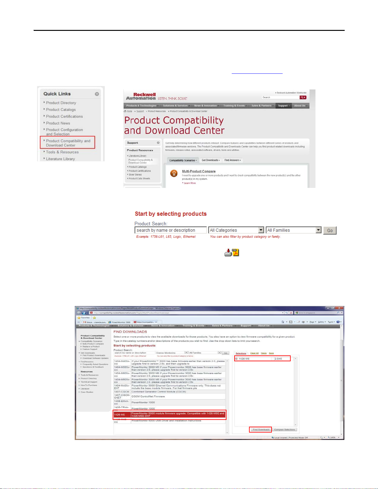
All PowerMonitor 5000 firmware release notes are available online with the
Product Compatibility and Download Center.
1. From the Quick Links list on http://www.ab.com
Compatibility and Download Center.
2. From the Compatibility Scenarios tab or the Get Downloads tab, search
for and choose your product.
, choose Product
3. Click the download icon to access product release notes.
4. Select the device catalog number (1).
The chosen catalog number appears under Selections (2).
5. When the correct catalog number appears under Selections, click Find
Downloads
(3).
Rockwell Automation Publication 1426-IN004A-EN-P - December 2013 3
Page 4
PowerMonitor 5000 Unit Firmware Revision Update
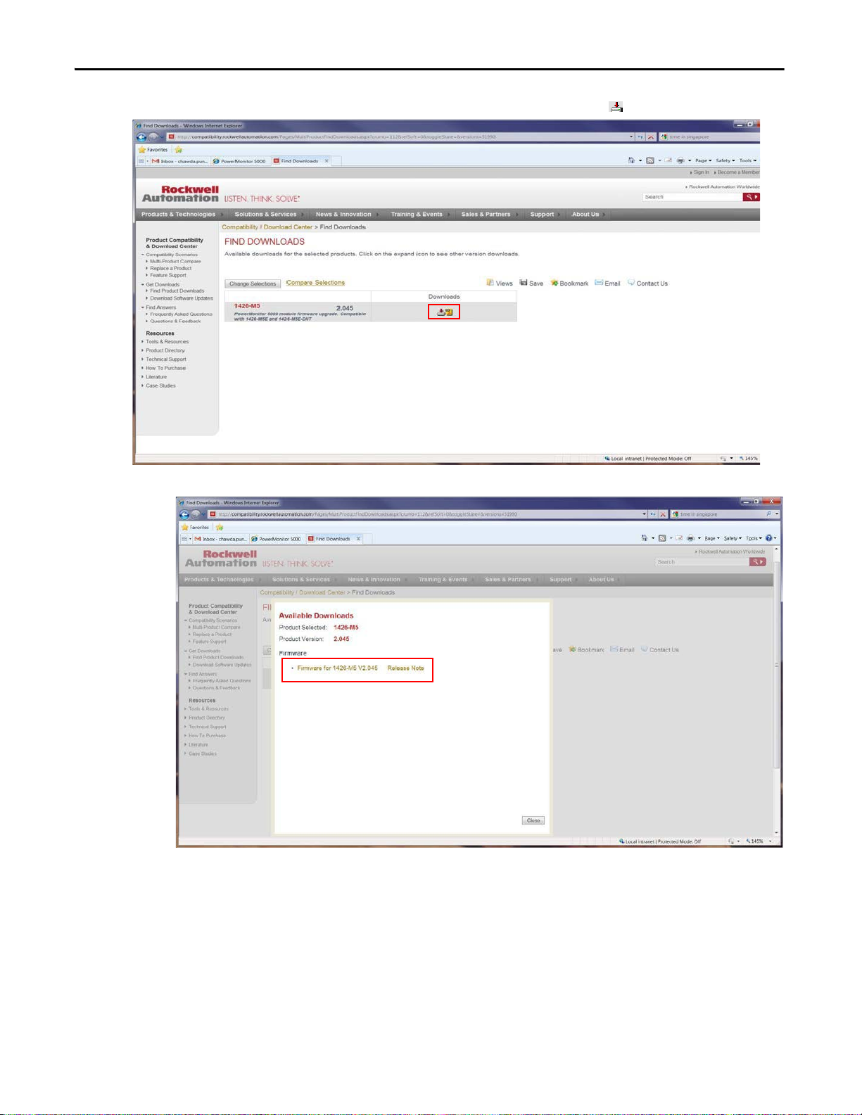
6. Under Downloads, click the download icon . .
7. Click the link for the firmware upgrade.
4 Rockwell Automation Publication 1426-IN004A-EN-P - December 2013
Page 5
PowerMonitor 5000 Unit Firmware Revision Update
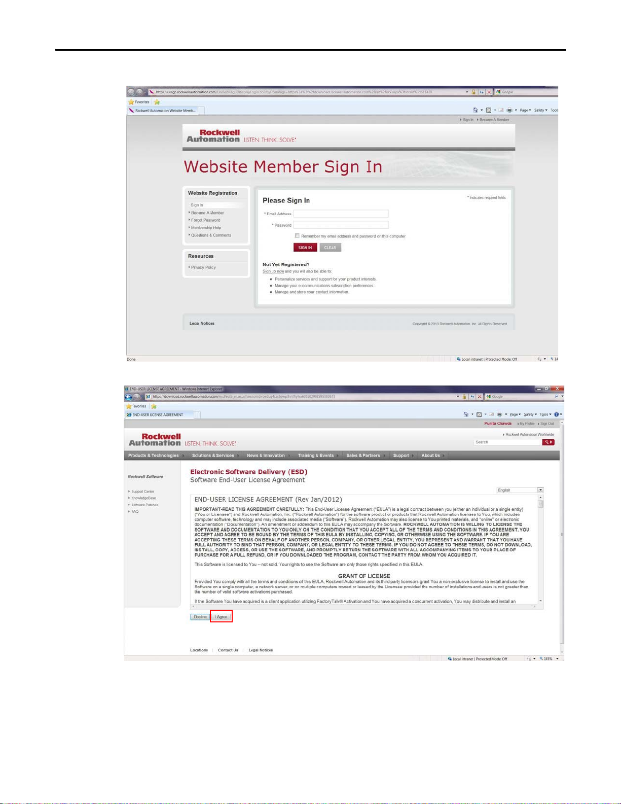
8. Log in by using the member email address and password.
9. After reading the Software End-User License Agreement, click I Agre e.
The download box opens.
Rockwell Automation Publication 1426-IN004A-EN-P - December 2013 5
Page 6

PowerMonitor 5000 Unit Firmware Revision Update
10. Once the download is complete, open the Download folder.
11. In the Download folder, double-click the 1426 Products folder.
6 Rockwell Automation Publication 1426-IN004A-EN-P - December 2013
Page 7

PowerMonitor 5000 Unit Firmware Revision Update
12. Open the WinZip file in the 1426-Products folder by double-clicking the
WinZip filename.
This example shows the 1426_M5_245.zip file.
13. Open the Windows Installer Package file in the WinZip folder by
double-clicking the file with the ‘msi’ extension.
This example shows the Windows Installer Package file
1426_M5_v245.msi.
Rockwell Automation Publication 1426-IN004A-EN-P - December 2013 7
Page 8

PowerMonitor 5000 Unit Firmware Revision Update
IMPORTANT
14. In the WinZip Caution dialog box, click Yes.
Update the Device Firmware Revision with the ControlFLASH Utility
The ControlFLASH™ utility
Directions on updating the firmware revision are found in the Update the
Device Firmware Revision with the ControlFLASH Utility section.
The ControlFLASH utility does not update the firmware if any Class 1
connections (generic or electronic data sheet (EDS) Add-on Profile
connections) exist. A connection exists if the Network Status indicator is either
solid green (connection active) or blinking red (connection timed out). Use the
Studio 5000 Logix Designer™ application to connect to the controller that owns
each connection and inhibit the connec tion. After successfully updating the
power monitor firmware, you can uninhibit the connections. Note that you can
edit connection properties to reflect the new power monitor firmware revision.
When updating the firmware revision, refer to the Access Product Firmware
Revision section for instructions on obtaining the latest firmware revision from
the Rockwell Automation download center.
1. Check Yes, I want to launch ControlFLASH and click Close.
opens.
8 Rockwell Automation Publication 1426-IN004A-EN-P - December 2013
Page 9

PowerMonitor 5000 Unit Firmware Revision Update
IMPORTANT
2. In the Select FactoryTalk Directory dialog box, click Local.
3. Click
OK.
4. On the Welcome to ControlFLASH dialog box, click Next.
5. Select the current catalog number of the device, based on the communication
type, and click Next:
• Refer to the Determine Communication Type
section to find the
relevant catalog number based on the communication type.
• Refer to the Catalog Number Format
section for an explanation of the
catalog number format.
There are three catalog number options provided, based on the
communication type: Ethernet, ControlNet, and DeviceNet. However, you must
select only one option that relates to the communication type in your
PowerMonitor 5000 unit. Refer to the Determine Communication Type
section
for more details on how to select the correct catalog number.
Rockwell Automation Publication 1426-IN004A-EN-P - December 2013 9
Page 10

PowerMonitor 5000 Unit Firmware Revision Update
TIP
TIP
6. In RSLinx software, navigate to the IP address of the device over the
Ethernet network, select the device, and click OK.
To update the firmware revision over the ControlNet or DeviceNet
network, navigate to the device through the network scanner in the RSLinx
software window.
To update the firmware revision via a USB connection, an RNDIS driver
must be installed. Refer to the PowerMonitor 5000 USB Driver
Installation and Configuration Installation Instructions, publication
1426-IN001,
for directions on installing the driver.
RSLinx Classic Lite software must be installed to continue with the upgrade
process.
To access the device IP address, the IP address must be added to the Ethernet
device’s driver address list in RSLinx software.
10 Rockwell Automation Publication 1426-IN004A-EN-P - December 2013
Page 11

PowerMonitor 5000 Unit Firmware Revision Update
TIP
7. Select the new firmware revision number of the device and click Next.
For the ControlFLASH utility, version 11 or later, the firmware revision has the
following format, 2.xxx. Therefore, firmware revision 2.50 appears as 2.050 in
the ControlFLASH utility.
8. On the Summary dialog box, click Finish.
Rockwell Automation Publication 1426-IN004A-EN-P - December 2013 11
Page 12

PowerMonitor 5000 Unit Firmware Revision Update
9. On the dialog box regarding updating the target device, click Yes.
10. On the Update Status dialog box, click OK to confirm that the update is
complete.
11. Check the device webpage to confirm that the firmware revision is updated
correctly.
12. Exit the ControlFLASH
utility.
12 Rockwell Automation Publication 1426-IN004A-EN-P - December 2013
Page 13

PowerMonitor 5000 Unit Firmware Revision Update
No network communication card
present.
ControlNet network
communication card present.
Determine Communication Type
There are two options to determine the catalog number based on the
communication type of the device.:
• Visual inspection
• View the PowerMonitor 5000 webpage
Option 1: Visual Inspec
• If there is no communication card present in the card slot, the
PowerMonitor 5000 unit has the catalog number format 1426-MxE.
tion
• If there is a ControlNet communication card in the card slot, the
PowerMonitor 5000 unit has the catalog number format 1426-MxE-CNT.
Rockwell Automation Publication 1426-IN004A-EN-P - December 2013 13
Page 14

PowerMonitor 5000 Unit Firmware Revision Update
TIP
TIP
DeviceNet network
communication card present.
• If there is a DeviceNet communication card in the card slot, the
PowerMonitor 5000 unit has the catalog number format 1426-MxE-DNT.
Option 2: View the PowerMonitor 5000 Webpage
The PowerMonitor 5000 webpage can be accessed in the following ways:
• Ethernet: If the PowerMonitor 5000 unit is able to communicate through
an Ethernet network, search for the device’s IP address in an Internet web
browser. The catalog number and installed communication type are listed
on the home page as shown in Figure 1
.
• USB: If the PowerMonitor 5000 unit is connected with a USB cable, search
for the default device’s IP address 192.168.169.3 in an Internet web
browser. The catalog number and installed communication type are listed
on the home page as shown in Figure 1
.
To access the dev ice’s webpage through a USB cable, an RNDIS driver must be
installed on the computer. Refer to the PowerMonitor 5000 USV Driver Installation
and Configuration Installation Instructions, publication
1426
-IN001, for directions
on installing the driver.
If a field-installed optional communication card is added to the device, the
webpage does not reflect the change in communication card information. In
this case, use the Option 1: V
isual Inspection method.
14 Rockwell Automation Publication 1426-IN004A-EN-P - December 2013
Page 15

PowerMonitor 5000 Unit Firmware Revision Update
1426-M5E-CNT
Bulletin
Number
Current Model
Number
Communication
Type
Figure 1 -
PowerMonitor 5000 Webpage
Catalog Number Format
In the ControlFLASH utility, the catalog number options are based on the model
number (for example, M5E or M6E) and the communication type: Ethernet (E);
ControlNet (CNT ), or DeviceNet (DNT ).
Figure 2 - Catalog Number Exam
ple
Rockwell Automation Publication 1426-IN004A-EN-P - December 2013 15
Page 16

PowerMonitor 5000 Unit Firmware Revision Update
Additional Resources
These documents contain additional information concerning related products
from Rockwell Automation.
Re
sourc
e
PowerMonitor 5000 Unit User Manual, publication
1426-UM001
PowerMonitor 5000 USB Driver Installation and
Configuration Installation Instructions, publication
1426-IN001
Product Certifications website, http://www.ab.com Provides declarations of conformity, certificates, and other
You can view or download publications at
literature/.
To order paper copies of technical documentation, contact your local
D
esc
ription
Provides information on installing and configuring the
PowerMonitor 5000 unit.
Provides instructions for installing the USB driver.
certification details.
http://www.rockwellautomation.com/
Allen-Bradley distributor or Rockwell Automation sales representative.
U.S. Allen-Bradley Drives Technical Support - Tel: (1) 262.512.8176, Fax: (1) 262.512.2222, E-mail: support@drives.ra.rockwell.com
Online: www.ab.com/support/abdrives
Allen-Bradley, Rockwell Software, Rockwell Automation, PowerMonitor, RSLinx, Studio 5000 Logix Designer, FactoryTalk, and ControlFLASH are trademarks of Rockwell Automation, Inc.
Trademarks not belonging to Rockwell Automation are property of their respective companies.
Publication 1426-IN004A-EN-P - December 2013
Copyright © 2013 Rockwell Auto mation, Inc. All rights reserved. Pr inted in the U.S.A.
 Loading...