

Page 1
Installation Instructions
PowerMonitor 5000 Unit Optional Communication Modules
Catalog Numbers
1426-COMM-DNT, 1426-COMM-CNT
About This Publication
Top ic Pa ge
About This Publication 1
Required Tools 1
Important User Information 2
Install a Communication Module 3
Replace a Communication Module 5
Additional Resources 5
This document provides instructions on how to install or replace an optional
communication module on a PowerMonitor™ 5000 unit. These are the available
optional communication modules:
• 1426-COMM-DNT - DeviceNet Optional Communication Module
• 1426-COMM-CNT - ControlNet Optional Communication Module
The communication module installs in the optional communication slot on the
front panel of the PowerMonitor 5000 unit. The installation is the same for all
communication modules regardless of communication type.
Required Tools
Before You Begin
You need the following tools:
• Torx 8 screwdriver
• Small flat-bladed screwdriver
WARNING: Do not connect or disconnect any communication cable with power
applied to this device or any device on the network. An electrical arc can occur
and could cause an explosion in hazardous location installations. Be sure that
power is removed or the area is nonhazardous before proceeding.
ATT EN TI ON : Work in a static free environment and wear a properly grounded
electrostatic discharge (ESD) wristband. Do not touch the communication
module connector or its internal circuitry to avoid ESD.
Page 2
PowerMonitor 5000 Unit Optional Communication Modules
IMPORTANT
Important User Information
Solid-state equipment has operational characteristics differing from those of electromechanical equipment. Safety
Guidelines for the Application, Installation and Maintenance of Solid State Controls (publication SGI-1.1
your local Rockwell Automation sales office or online at http://www.rockwellautomation.com/literature/
important differences between solid-state equipment and hard-wired electromechanical devices. Because of this difference,
and also because of the wide variety of uses for solid-state equipment, all persons responsible for applying this equipment
must satisfy themselves that each intended application of this equipment is acceptable.
In no event will Rockwell Automation, Inc. be responsible or liable for indirect or consequential damages resulting from the
use or application of this equipment.
The examples and diagrams in this manual are included solely for illustrative purposes. Because of the many variables and
requirements associated with any particular installation, Rockwell Automation, Inc. cannot assume responsibility or
liability for actual use based on the examples and diagrams.
No patent liability is assumed by Rockwell Automation, Inc. with respect to use of information, circuits, equipment, or
software described in this manual.
Reproduction of the contents of this manual, in whole or in part, without written permission of Rockwell Automation, Inc.,
is prohibited.
available from
) describes some
Throughout this manual, when necessary, we use notes to make you aware of safety considerations.
WARNING: Identifies information about practices or circumstances that can cause an explosion in a hazardous environment,
which may lead to personal injury or death, property damage, or economic loss.
ATTENTION: Identifies information about practices or circumstances that can lead to personal injury or death, property
damage, or economic loss. Attentions help you identify a hazard, avoid a hazard, and recognize the consequence.
SHOCK HAZARD: Labels may be on or inside the equipment, for example, a drive or motor, to alert people that dangerous
voltage may be present.
BURN HAZARD: Labels may be on or inside the equipment, for example, a drive or motor, to alert people that surfaces may
reach dangerous temperatures.
Identifies information that is critical for successful application and understanding of the product.
2 Rockwell Automation Publication 1426-IN002A-EN-P - April 2013
Page 3

PowerMonitor 5000 Unit Optional Communication Modules
IMPORTANT
Virtual Wiring
Correction
---- S1
S2
---- S3
S4
---- S com
S com
---- K
Y
---- Z
R1 O
---- R1 com
R1 C
---- R2 O
R2 com
---- R2 C
R3 O
---- R3 com
R3 C
Module
status
Network
status
Config Loc
EtherNet/IP
Power
USB
Device
USB
Host
LNK
ACT
I 1
I 2
I 3
I 4
L1
L2
GND
24V
com
V1
V2
V3
VN
VG
C O M M U N I C A T I O N P O R T
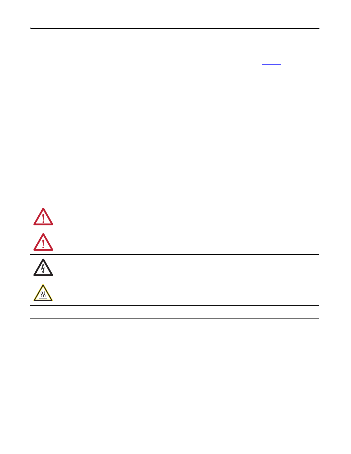
PowerMonitor 5000
Commu nication
Port Cover
Install a Communication Module
Follow these steps to install a new communication module.
1. Disconnect control and voltage sensing power from the power monitor.
2. Remove the optional communication port cover by prying gently with a
small, flat-bladed screwdriver.
Z
K
Y
Rx com Rx C
Rx O
Internal
S n
24 VDC
Scom
3. Verify that the fastening screws in the communication module are backed
out approximately 4 mm (0.16 in.) and that the fastening cams do not
protrude from the bottom of the module.
4. Carefully slide the communication module flat against the circuit board in
the slot, aligning the tabs along the module’s edges with the guides in the
socket.
When installing the module into the socket, make sure that the
communication module is properly aligned into the socket prior to applying
any force. Rough handling and/or excessive force in combination with
misalignment can cause mechanical damage to the communication module or
the power monitor.
Rockwell Automation Publication 1426-IN002A-EN-P - April 2013 3
Page 4
PowerMonitor 5000 Unit Optional Communication Modules
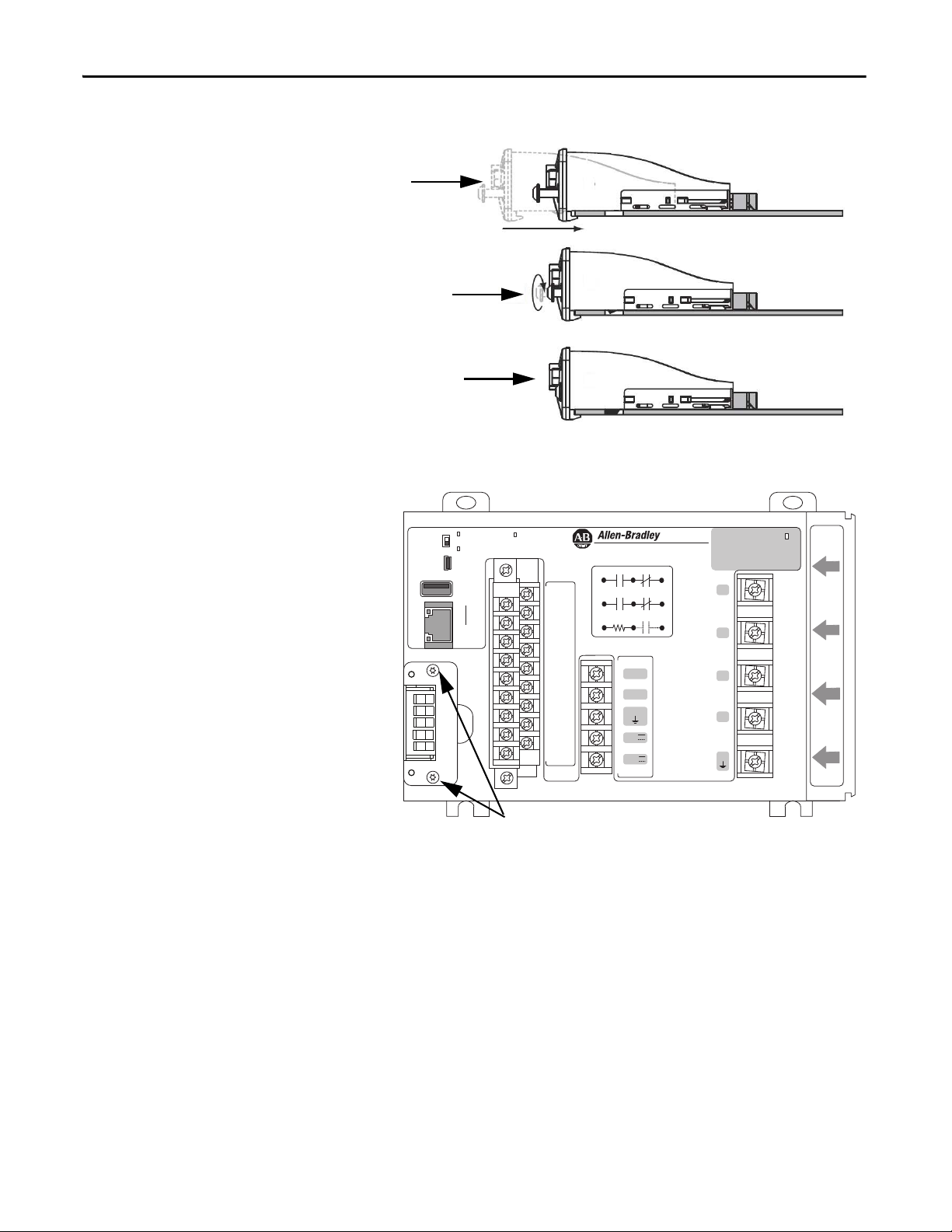
Step 5 Insert module
Step 6 Tighten to
0.25 N•m
(2.2 lb•in)
Step 7 Module bezel
aligns with the
front panel.
1
DS NS
2345
DeviceNet
Tighten to
0.25 N•m (2.2 lb•in)
5. Gently insert the module into its socket until the module is seated.
6. Tighten the screws with a Torx 8 screwdriver to 0.25 N•m (2.2 lb•in).
Config Loc
LNK
ACT
Module
status
Network
status
USB
Device
USB
Host
EtherNet √IP
Power
PowerMonitor 5000
Z
K
Y
---- S1
S2
---- S3
S4
---- S com
S com
---- K
Y
---- Z
R1 O
---- R1 com
R1 C
---- R2 O
R2 com
---- R2 C
R3 O
---- R3 com
R3 C
Rx O
Internal
24 VDC
Rx com Rx C
S n
L1
L2
GND
24V
com
Scom
V1
V2
V3
VN
VG
Virtual Wiring
Correction
7. Check that the module is properly seated.
The rear edge of the module bezel aligns with the front panel of the power
monitor. Tightening the screws engages the fastening cams with holes in
the circuit board, which helps resist efforts to remove the card.
I 1
I 2
I 3
I 4
4 Rockwell Automation Publication 1426-IN002A-EN-P - April 2013
Page 5
PowerMonitor 5000 Unit Optional Communication Modules
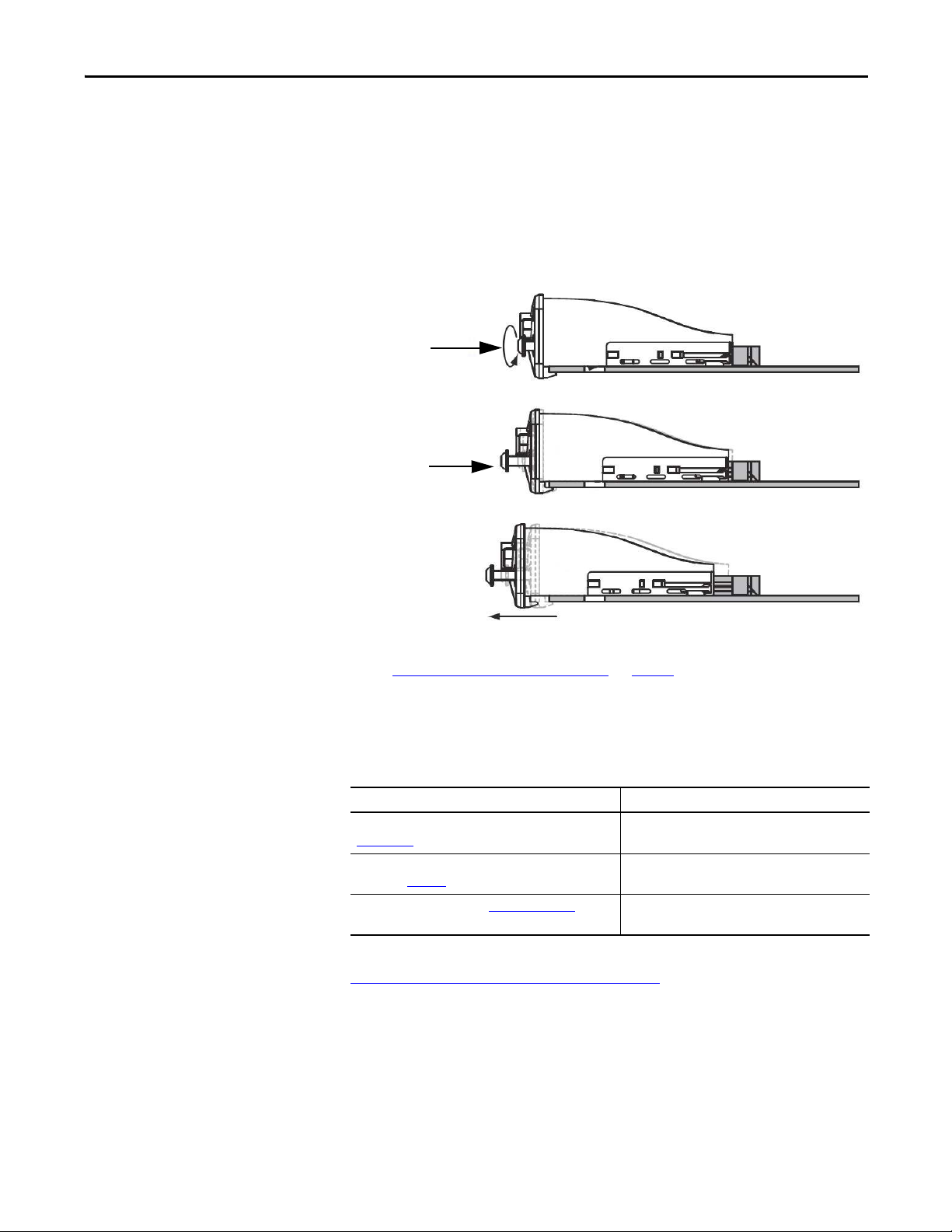
Step 2 Use Torx 8
Screwdriver
Step 2 Back out
approximately
4 mm
(0.16 in.)
Step 3 Remove the
communication
module.
Replace a Communication Module
Follow these steps to replace a communication module.
1. Disconnect control and voltage sensing power from the power monitor.
2. With a Torx 8 screwdriver, back out the fastening screws approximately
4 mm (0.16 in.).
Do not remove the screws.
3. Gently remove the communication module from the power monitor.
Additional Resources
4. Install the new communication module by following steps 3…7 under
Install a Communication Module
on page 3.
These documents contain additional information concerning related products
from Rockwell Automation.
Resource Description
PowerMonitor 5000 Unit User Manual, publication
1426-UM001
Industrial Automation Wiring and Grounding Guidelines,
publication 1770-4.1
Product Certifications website, http://www.ab.com
Provides information on installing, configuring, and
using the PowerMonitor 5000 unit.
Provides general guidelines for installing a Rockwell
Automation® industrial system.
Provides declarations of conformity, certificates, and
other certification details.
You can view or download publications at
http:/www.rockwellautomation.com/literature/
. To order paper copies of
technical documentation, contact your local Allen-Bradley distributor or
Rockwell Automation sales representative.
Rockwell Automation Publication 1426-IN002A-EN-P - April 2013 5
Page 6

Rockwell Automation Support
Rockwell Automation provides technical information on the Web to assist you in using its products.
At http://www.rockwellautomation.com/support
code and links to software service packs, and a MySupport feature that you can customize to make the best use of these
tools. You can also visit our Knowledgebase at http://www.rockwellautomation.com/knowledgebase
information, support chat and forums, software updates, and to sign up for product notification updates.
, you can find technical manuals, technical and application notes, sample
for FAQs, technical
For an additional level of technical phone support for installation, configuration, and troubleshooting, we offer
SM
Te c h C o nn e c t
representative, or visit http://www.rockwellautomation.com/support/
support programs. For more information, contact your local distributor or Rockwell Automation
.
Installation Assistance
If you experience a problem within the first 24 hours of installation, review the information that is contained in this
manual. You can contact Customer Support for initial help in getting your product up and running.
United States or Canada 1.440.646.3434
Outside United States or Canada Use the Worldwide L ocator
local Rockwell Automation representative.
at http://www.rockwellautomation.com/rockwellautomation/support/overview.page, or contact your
New Product Satisfaction Return
Rockwell Automation tests all of its products to help ensure that they are fully operational when shipped from the
manufacturing facility. However, if your product is not functioning and needs to be returned, follow these procedures.
United States Contact your distributor. You must provide a Customer Support case number (call the phone number above to obtain one) to your
distributor to complete the return process.
Outside United States Please contact your local Rockwell Automation representative for the return procedure.
Documentation Feedback
Your comments will help us serve your documentation needs better. If you have any suggestions on how to improve this
document, complete this form, publication RA-DU002
Allen-Bradley, Rockwell Software, Rockwell Automation, PowerMonitor, and TechConnect are trademarks of Rockwell Automation, Inc.
Trademarks not belonging to Rockwell Automation are property of their respec tive companies.
Publication 1426-IN002A-EN-P - April 2013
, available at http://www.rockwellautomation.com/literature/.
Copyright © 2013 Rockwell Auto mation, Inc. All rights reserved. Pr inted in the U.S.A.
 Loading...