

Page 1

Installation Instructions
Outside Air Temperature Transmitter
Catalog Number(s) 1414-ITZ03FAOAA,
1414-ITZ02FAOAA, 1414-CTZ03FAOAA
About Outside Air Temperature Transmitter
Designed specifically for outside air temperature measurement, this single-unit
device comes in a weather-proof gasketed PVC enclosure with a sun and wind
shield to protect it from false readings.
The temperature transmitter is designed to convert 1000 ohm RTD signal into an
analog output with ±0.15°C Class A, ±0.30°C Class B and 0.1% FSO accuracy for the
board..
Publication 1414-IN010A-EN-P - October 2005
Page 2
2 Outside Air Temperature Transmitter
Important User Information
Solid state equipment has operational characteristics differing from those of electromechanical equipment.
Safety Guidelines for the Application, Installation and Maintenance of Solid State Controls (Publication
SGI-1.1 available from your local Rockwell Automation sales office or online at
http://www.literature.rockwellautomation.com) describes some important differences between solid state
equipment and hard-wired electromechanical devices. Because of this difference, and also because of the
wide variety of uses for solid state equipment, all persons responsible for applying this equipment must
satisfy themselves that each intended application of this equipment is acceptable.
In no event will Rockwell Automation, Inc. be responsible or liable for indirect or consequential damages
resulting from the use or application of this equipment.
The examples and diagrams in this manual are included solely for illustrative purposes. Because of the many
variables and requirements associated with any particular installation, Rockwell Automation, Inc. cannot
assume responsibility or liability for actual use based on the examples and diagrams.
No patent liability is assumed by Rockwell Automation, Inc. with respect to use of information, circuits,
equipment, or software described in this manual.
Reproduction of the contents of this manual, in whole or in part, without written permission of Rockwell
Automation, Inc., is prohibited.
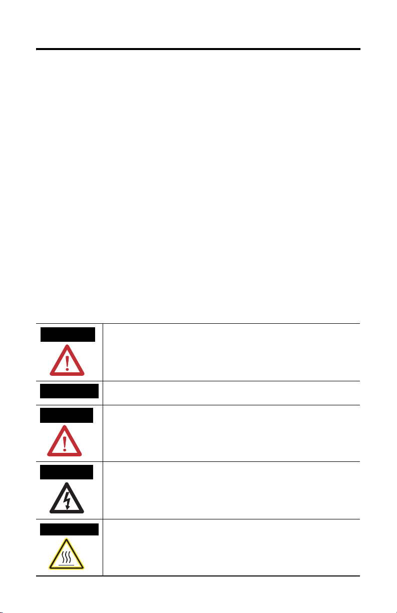
Throughout this manual, when necessary, we use notes to make you aware of safety considerations.
WARNING
IMPORTANT
ATTENTION
SHOCK HAZARD
BURN HAZARD
Identifies information about practices or circumstances that can cause an explosion in
a hazardous environment, which may lead to personal injury or death, property
damage, or economic loss.
Identifies information that is critical for successful application and understanding of
the product.
Identifies information about practices or circumstances that can lead to personal injury
or death, property damage, or economic loss. Attentions help you identify a hazard,
avoid a hazard and recognize the consequences.
Labels may be located on or inside the equipment (e.g., drive or motor) to alert people
that dangerous voltage may be present.
Labels may be located on or inside the equipment (e.g., drive or motor) to alert people
that surfaces may be dangerous temperatures.
Publication 1414-IN010A-EN-P - October 2005
Page 3

Outside Air Temperature Transmitter 3
Install the Outside Air Temperature Transmitter
For best results locate the sensor on the north side of the structure high under an
eave to prevent incorrect readings from direct sunlight and damage due to the
elements. Mount the OSA enclosure with the sensor module facing down to
prevent the accumulation of dirt or water.
North
OSA Sensor
Wire/Connect the Outside Air Temperature Sensor
The wiring diagram shows typical connections to a controller. For 4 to 20 mA loop
signal, only the PWR and OUT terminals are used.
2-wire RTD
Sensor
Temperature Transmitter
NEG
SEN
EXC
Loop power supply
+ 24 VDC -
OUT
PWR
COM
SPAN
ZERO
Analog Current Input
ANL IN 0 +
ANL IN 0 -
ANL COM
Field Calibration
The unit can be calibrated in the field by using precision resistor values equal to the
zero and span of the transmitter temperature range.
1. Disconnect the sensor from the transmitter and connect the resistor that
represents the zero value to the EXC and NEG terminals.
Publication 1414-IN010A-EN-P - October 2005
Page 4

TIP
If the unit uses a three-wire sensor, a jumper must be placed
between EXC and SEN.
2. Adjust the ZERO pot until the desired output is achieved.
3. Connect the resistor that represents the span value to the EXC and NEG
terminals.
4. Adjust the SPAN pot until the desired output is achieved.
Repeat these steps until no further adjustment is required.
Specifications
Duct Temperature Sensor Specifications
Specification Value
Operating Temperature Range -50 … 50 ° C (-58 … 122 °F)
Wiring Connections Terminal blocks
Enclosures Metal 1/2 LBA
Sensor Types 1000 Ω platinum Class A 0.15°C , Class B 0.3°C, 0.1% FSO for the board
All other trademarks are the property of their respective holders, and are hereby acknowledged.
Publication 1414-IN010A-EN-P - October 2005 PN 40055-240-01(1)
Supersedes Publication XXXX-X.X.X - Month Year Copyright © 2005 Rockwell Automation, Inc. A ll rights reserved. Printed in t he U.S.A.
 Loading...