

Page 1

Installation Instructions
Air Flow Transmitter
Catalog Number 1414-IFZ35FGDAA
Before you Install
In order for the transmitter to operate correctly all the information supplied in this
document must be followed.
IMPORTANT
Transmitter must not be mounted near elbows , damper vanes or
other restrictions that may cause turbulent air flow. Always install
in a straight section of duct.
About the Air Flow Transmitter
The Air Flow Transmitter is an airflow transducer which may be used for control,
monitoring and regulation of airflow speed in fresh air and ventilation units etc.
The transmitter registers airflow speed according to a thermal principle based on
the fact that the cooling action of air increases with airspeed. The action is
measured and converted to a 4 to 20 ma or a 0 to 10V signal corresponding to
airflow speeds from 0.5 to 8 m/s (100 to 1575 ft/min) or 0.5 to 16 m/s (100 to 3150
ft/min).
The micro-processor based electronics provides an output signal that is linear and
corrected for temperature changes. If a standard analog instrument is connected the
airflow speed and temperature can be read remotely.
The transmitter has a separate 0 to 10 Vdc output signal for measurement of the air
temperature 0 to 50ºC (32 to 122°F).
Publication 1414-IN001A-EN-P - October 2005
Page 2
2 Air Flow Transmitter
Important User Information
Solid state equipment has operational characteristics differing from those of electromechanical equipment.
Safety Guidelines for the Application, Installation and Maintenance of Solid State Controls (Publication
SGI-1.1 available from your local Rockwell Automation sales office or online at
http://www.literature.rockwellautomation.com) describes some important differences between solid state
equipment and hard-wired electromechanical devices. Because of this difference, and also because of the
wide variety of uses for solid state equipment, all persons responsible for applying this equipment must
satisfy themselves that each intended application of this equipment is acceptable.
In no event will Rockwell Automation, Inc. be responsible or liable for indirect or consequential damages
resulting from the use or application of this equipment.
The examples and diagrams in this manual are included solely for illustrative purposes. Because of the many
variables and requirements associated with any particular installation, Rockwell Automation, Inc. cannot
assume responsibility or liability for actual use based on the examples and diagrams.
No patent liability is assumed by Rockwell Automation, Inc. with respect to use of information, circuits,
equipment, or software described in this manual.
Reproduction of the contents of this manual, in whole or in part, without written permission of Rockwell
Automation, Inc., is prohibited.
Throughout this manual, when necessary, we use notes to make you aware of safety considerations.
WARNING
IMPORTANT
ATTENTION
SHOCK HAZARD
BURN HAZARD
Identifies information about practices or circumstances that can cause an explosion in
a hazardous environment, which may lead to personal injury or death, property
damage, or economic loss.
Identifies information that is critical for successful application and understanding of
the product.
Identifies information about practices or circumstances that can lead to personal injury
or death, property damage, or economic loss. Attentions help you identify a hazard,
avoid a hazard and recognize the consequences.
Labels may be located on or inside the equipment (e.g., drive or motor) to alert people
that dangerous voltage may be present.
Labels may be located on or inside the equipment (e.g., drive or motor) to alert people
that surfaces may be dangerous temperatures.
Publication 1414-IN001A-EN-P - October 2005
Page 3
Air Flow Transmitter 3
Install Air Flow Transmitter
The transmitter is mounted in such a way that the airflow passes the sensor head.
The power supply cables to the transmitter should be kept separated from high
voltage lines where heavy transients may occur.
The transmitter can be mounted in airflow channels with a diameter or channel
width of 100 to 370 mm (4 in to 15 in)
Wire and Connect Air Flow Transmitter
The length of the cable is not critical. Avoid placing it in parallel with other cables,
which may induce electrical noise on the voltage signal and thus disturb the
function of the transmitter.
The best installation is obtained with a separate cable to the transmitter. It is
recommended to use a shielded cable to the transmitter as this improves immunity
against noise when it is used in light-industrial areas. The shield should be
terminated at the supply point but not terminated at the transmitter.
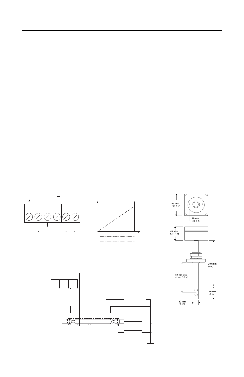
Wiring Diagram
Tem p 0- 10 VDC
6 5 4 3 2 1
Flow 0-10VDC
GRD
Flow 4-20Ma
- +
24 VAC
16-30 VDC
Wire to a Programmable Controller
Air Flow Transmitter
132
465
- +
Ground
Power
24 VAC,
Flow, 0-1 0 V
Temp 0-10 V
16-30 V DC
Flow, 4-20 mA
Output Signals Scales
mA
20
4
0
0
Loop power supply
Analog Current Input
V ou t( d c)
10
(3150 ft /min)
16 m/s
(1575 ft /min)
8 m/s
+ 24 VDC -
ANL IN 0 +
ANL IN 0 -
ANL COM
Publication 1414-IN001A-EN-P - October 2005
Dimensions
Page 4

Post-installation
The module is delivered with the range set at 0.5 to 8 m/sec (100 to 1575 ft/min). If
jumper SW1 is removed on the printed circuit board, the range 0.5 to 16 m/sec (100
to 3150 ft/min) is obtained.
Maintenance
As the thermal measuring principle is based on the cooling principle of the air, dirt
accumulation on the sensor will reduce the measuring accuracy. If the transmitter is
used in dirty air, the sensor head should be cleaned at suitable intervals.
Specifications
Air Flow Transmitter Specifications
Specification Value
Airflow speed 0.5…8 m/s (100…1575 ft/m, 0.5…16 m/s (100…3150 ft/m)
Standard current signal 4…20 ma (loop resistance < 500Ω)
Standard voltage signal 0…10V (max. 5mA)
Air temperature –10ºC…+60ºC (+14°F…140°F)
Ambient temperature –20ºC…+50ºC (-4°F…+122°F)
AC voltage supply 24V ac ±10% (120 ma)
DC voltage supply 16…30V dc (80 ma)
Absolute accuracy ±5% of full scale
Rise time 20 sec
Time constant 5 sec
Depth of insertion in channel 50…200 mm (2…8 in.)
Dimensions (HxWxD) 80 x 80 x 55 mm(3.15 x 3.15 x 2.17 in)
All other trademarks are the property of their respective holders, and are hereby acknowledged.
Publication 1414-IN001A-EN-P - October 2005 PN 40055-231-01(1)
Supersedes Publication XXXX-X.X.X - Month Year Copyright © 2005 Rockwell Automation, Inc. A ll rights reserved. Printed in t he U.S.A.
 Loading...