

Page 1
Installation Instructions
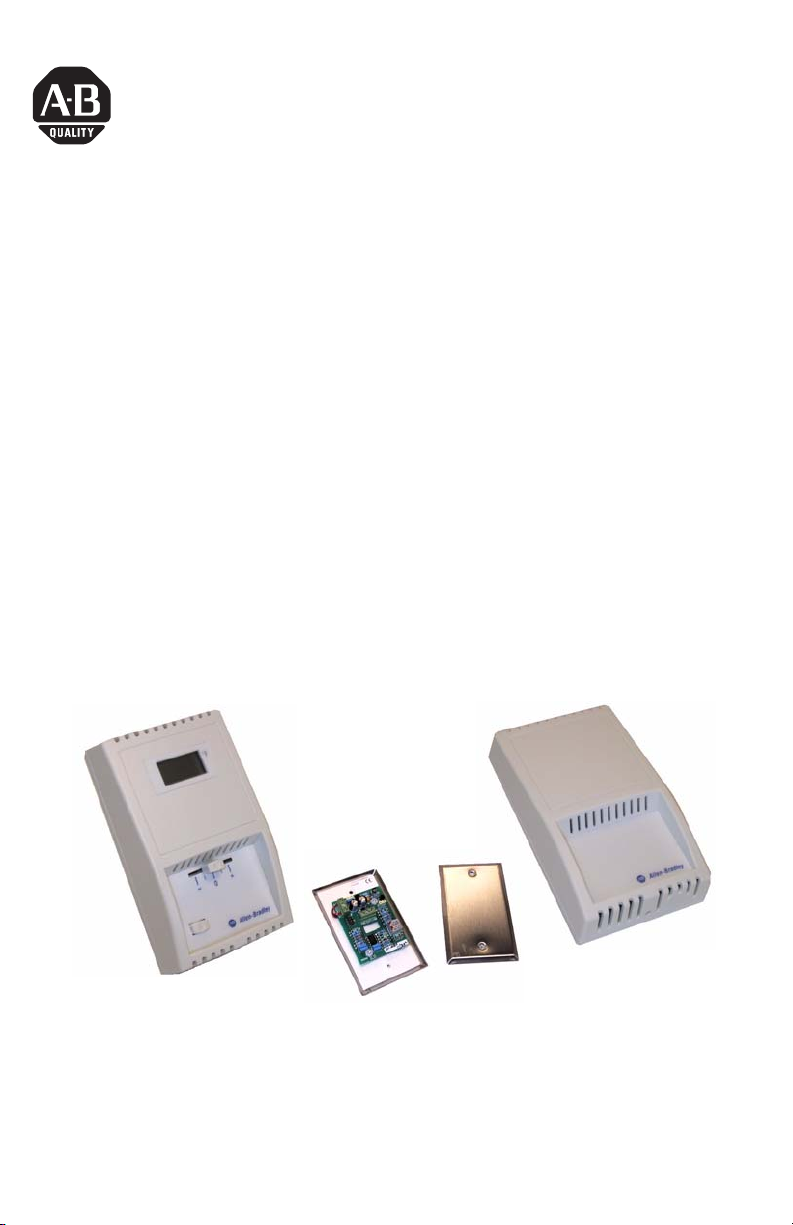
Space Temperature Transmitter
Catalog Number(s) 1414-CTZ03PBRAA,
1414-CTD03PBRAA, 1414-CTO03PBRAA,
1414-CTS03PBRAA, 1414-CTT03PBRAA,
1414-ITS03PBRAA, 1414-ITT03SBRAA,
1414-ITZ02GBRAA, 1414-ITD02GBRAA,
1414-ITO02GBRAA, 1414-ITT02SBRAA,
1414-ITO03GBRAA, 1414-ITS02GBRAA,
1414-ITZ03PBRAA, 1414-ITD03PBRAA
Publication 1414-IN012A-EN-P - October 2005
Page 2
2 Space Temperature Transmitter
Important User Information
Solid state equipment has operational characteristics differing from those of electromechanical equipment.
Safety Guidelines for the Application, Installation and Maintenance of Solid State Controls (Publication
SGI-1.1 available from your local Rockwell Automation sales office or online at
http://www.literature.rockwellautomation.com) describes some important differences between solid state
equipment and hard-wired electromechanical devices. Because of this difference, and also because of the
wide variety of uses for solid state equipment, all persons responsible for applying this equipment must
satisfy themselves that each intended application of this equipment is acceptable.
In no event will Rockwell Automation, Inc. be responsible or liable for indirect or consequential damages
resulting from the use or application of this equipment.
The examples and diagrams in this manual are included solely for illustrative purposes. Because of the many
variables and requirements associated with any particular installation, Rockwell Automation, Inc. cannot
assume responsibility or liability for actual use based on the examples and diagrams.
No patent liability is assumed by Rockwell Automation, Inc. with respect to use of information, circuits,
equipment, or software described in this manual.
Reproduction of the contents of this manual, in whole or in part, without written permission of Rockwell
Automation, Inc., is prohibited.
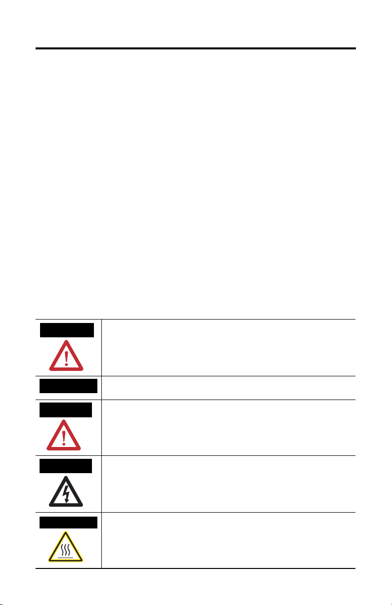
Throughout this manual, when necessary, we use notes to make you aware of safety considerations.
WARNING
IMPORTANT
ATTENTION
SHOCK HAZARD
BURN HAZARD
Identifies information about practices or circumstances that can cause an explosion in
a hazardous environment, which may lead to personal injury or death, property
damage, or economic loss.
Identifies information that is critical for successful application and understanding of
the product.
Identifies information about practices or circumstances that can lead to personal injury
or death, property damage, or economic loss. Attentions help you identify a hazard,
avoid a hazard and recognize the consequences.
Labels may be located on or inside the equipment (e.g., drive or motor) to alert people
that dangerous voltage may be present.
Labels may be located on or inside the equipment (e.g., drive or motor) to alert people
that surfaces may be dangerous temperatures.
Publication 1414-IN012A-EN-P - October 2005
Page 3

Space Temperature Transmitter 3
About Space Temperature Transmitter
The unit is designed to convert a 1000 ohm RTD signal and provide a 4 to 20 mA
analog output with ±0.15°C Class A, ±0.30°C Class B and 0.1% FSO accuracy for the
board.
Designed for temperature measurement of occupied spaces. Featuring several
enclosure styles to accommodate various job requirements.
Install Space Temperature Transmitter
Transmitters are mounted directly on a wall or to a wall box. For the most accurate
results, units should be mounted on an inside wall to a wall box, approximately 3
to 5 feet from the floor, away from any supply air exhausts and other sources of
heat or cold. The enclosure cover is held in place with a locking tab located to the
left of center at the bottom of the enclosure. Remove the setpoint knob before
removing the cover. Use a set screw (1/16” or 1.5 mm) to lock the cover at the
bottom of the enclosure after installation.
Wire and Connect Space Temperature Transmitter
Connect the transmitter to the controller using 18 to 22 AWG twisted pair wiring.
The transmitter requires two wires for DC 4 to 20 mA loop-powered operation. The
use of shielded cable is optional but recommended for the highest noise immunity.
Do not route signal wires in the same conduit with power cables as signal
degradation may occur. The controller Analog Input (AI) must be selected to match
the transmitter output before power is applied. The AI type must be a current input
with 250 or 500 ohm impedance. All transmitters have an operating range of
0 to 70 °C (32 to 158 °F). The transmitter board should not be mounted where
temperatures exceed these values. See the connection diagram for more details.
Options, if included on your unit, are wired at the Setpoint and Override terminals.
The Return terminal is used as the common for both of these options. The LCD
display is powered by the same supply as the transmitter.
Wire to a Programmable Controller
This section indicates typical wiring connections to a programmable controller.
When you use this connection scheme, the nominal setpoint is wired to a 0 to 20
mA analog input. The setpoint current signal is reverse acting with respect to the
position of the setpoint slider. The setpoint current varies from 1.2 mA at the
minimum position to 0.8 mA at the maximum position. An analog input with 14-bit
resolution provides a resolution of 0.06°F over a range of 60 to 80°F. Analog
Publication 1414-IN012A-EN-P - October 2005
Page 4

4 Space Temperature Transmitter
module configuration or user programming in the controller is required to scale the
raw analog signal to engineering units.
The temperature transmitter is wired to a 4 to 20 mA analog input. The ‘Common’
terminal is only wired when the transmitter is used in a 3-wire connection. A
2-wire, loop-powered connection is shown.
Loop power supply
+ 24 VDC -
Analog Current Input
Temperature Transmitter with Setpoint and Override
SETPOINT
RETURN
OVERRIDE
POWER
SIGNAL OUT
COMMON
ANL IN 0 +
ANL IN 0 -
ANL IN 1 +
ANL IN 1 -
ANL COM
24 VDC Discrete Input
DI 0
DI 1
DI COM
This is the configuration of a 1769-IF4 analog input for the example.
Publication 1414-IN012A-EN-P - October 2005
Page 5

Space Temperature Transmitter 5
Setpoint Input Data Range
Slider Position Temperature Setpoint Engineering Units
Minimum 60°F 1200 (1.2 mA)
Maximum 80°F 800 (0.8 mA)
This example rung converts the analog input engineering value into the setpoint in
degrees F.
Compute
Dest Temp_SP_deg_F
Expression 120 - 0.05 * Local: 1:I.CH0Data
This is the configuration of a 1756-IF16 analog input for the example. The module’s
channel data expresses the setpoint in degrees F withouit further converstion.
CPT
0.0
Specifications
Space Temperature Transmitter Specifications
Specification Value
Transmitter Accuracy 0.1% FSO
Temperature Sensor Type 1000 ohm platinum RTD 0.15°C, 0.3°C
Output Signal 4…20 mA current loop
Publication 1414-IN012A-EN-P - October 2005
Page 6

6 Space Temperature Transmitter
Space Temperature Transmitter Specifications
Operating Temperature 0 … 70°C (32 … 158°F)
Operating Humidity 0 … 95% RH (non-condensing)
4-20 mA Loop Power Supply 18 … 35 Vdc (with 250 ohm load and no LCD)
22 … 35 Vdc (with 250 ohm load and LCD)
Loop Current (Minimum) 2 mA nominal (occurs with shorted sensor)
Loop Current (Maximum) 22.5 mA nominal (occurs with open sensor)
Maximum Loop Load > 600 ohms at 24 Vac/dc with no LCD,
Protection Circuitry Reverse voltage protected and output limited
Display Accuracy ±0.2ºF over full range with respect to the output signal
Display Units ºF (Factory set)
Display Range 32.0 … 95°F
Display Resolution 0.1ºF for display of 00.0 to 99.9
Slide-pot 20 – 30K (L-R)
Switch Normally open pushbutton, 0.4 VA at 24 Vac/dc standard
> 325 ohms with LCD
Publication 1414-IN012A-EN-P - October 2005
Page 7

Space Temperature Transmitter 7
Publication 1414-IN012A-EN-P - October 2005
Page 8

All other trademarks are the property of their respective holders, and are hereby acknowledged.
Publication 1414-IN012A-EN-P - October 2005 PN 40055-242-01(1)
Supersedes Publication XXXX-X.X.X - Month Year Copyright © 2005 Rockwell Automation, Inc. A ll rights reserved. Printed in t he U.S.A.
 Loading...