

Page 1
Installation Instructions
Duct Temperature Transmitter
Catalog Numbers
1414-CTQ03AIDAA, 1414-CTQ03PDDAA, 1414-CTQ03PCDAA,
1414-CTQ03PBDAA, 1414-CTP03PDDAA, 1414-CTP03PCDAA, 1414-CTP03PBDAA,
1414-ITQ03ADDAA, 1414-ITQ03ACDAA, 1414-ITQ03ABDAA, 1414-ITP03ADDAA,
1414-ITP03ACDAA, 1414-ITP03ABDAA, 1414-ITQ02ADDAA, 1414-ITQ02ACDAA,
1414-ITQ02ABDAA, 1414-ITP02ADDAA, 1414-ITP02ACDAA, 1414-ITP02ABDAA
Top ic Pa ge
About the Duct Temperature Transmitter 1
Important User Information 2
Install the Duct Temperature Transmitter 3
Field Calibration 5
Specifications 5
Dimensions 7
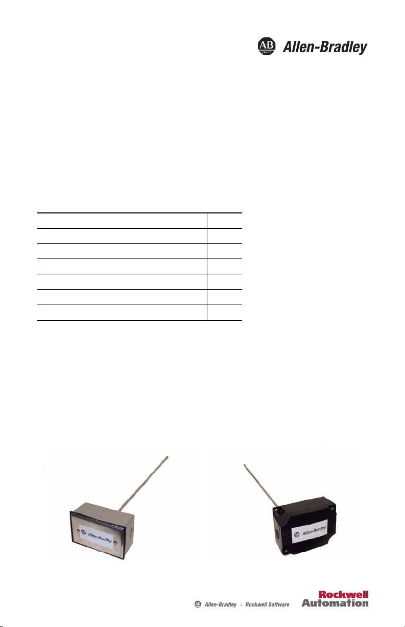
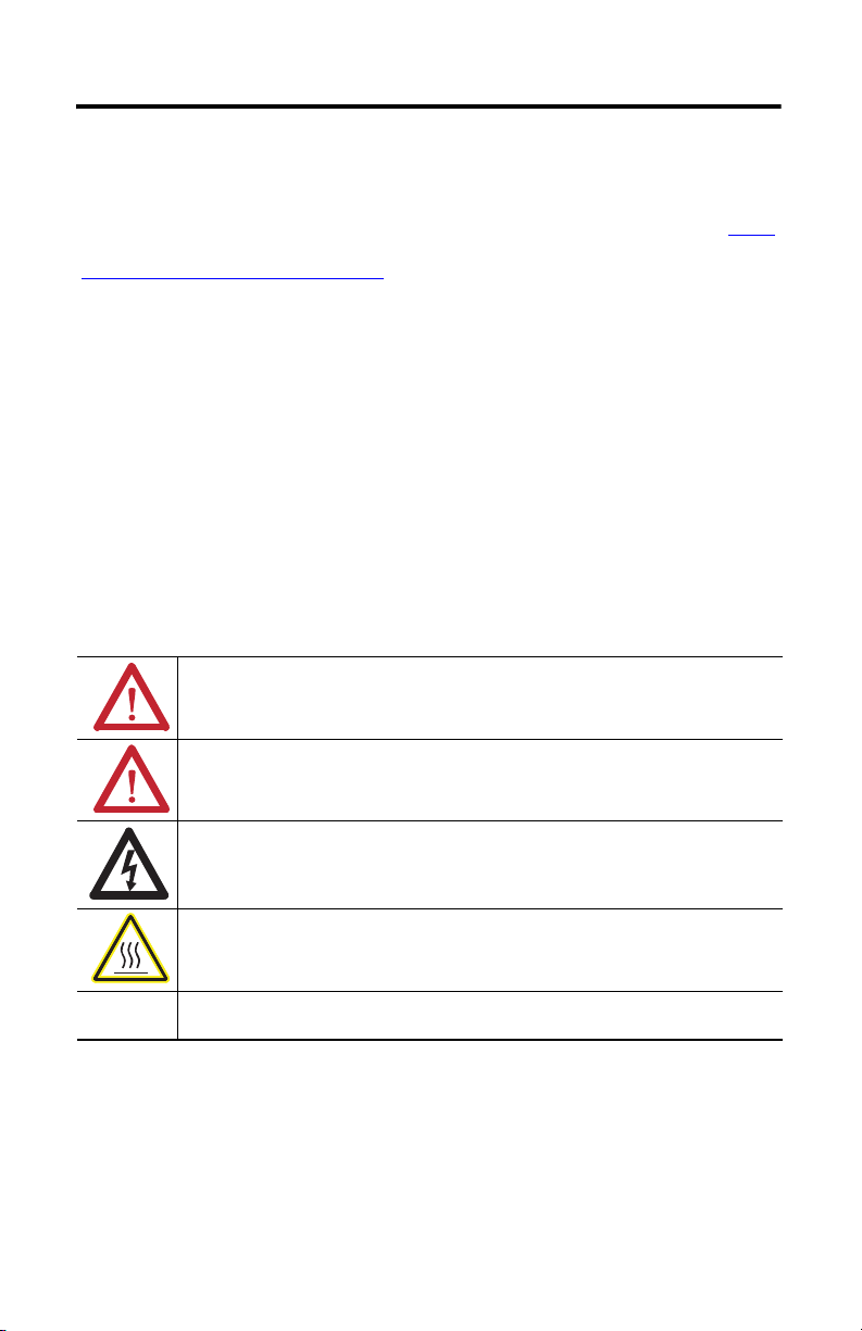
About the Duct Temperature Transmitter
This duct temperature transmitter is designed for single point monitoring. It is available with
two probe lengths and enclosures to fit commercial and light-industrial applications. The duct
temperature transmitter provides a 4…20 mA current signal proportional to the sensed
temperature and is loop powered.
The temperature transmitter is designed to convert 1000 ohm RTD signal into an analog output
with ±0.15 °C Class A, ±0.30 °C Class B, and 0.1% FSO accuracy for the board.
Page 2
2 Duct Temperature Transmitter
Important User Information
Solid-state equipment has operational characteristics differing from those of electromechanical equipment.
Safety Guidelines for the Application, Installation and Maintenance of Solid State Controls (Publication SGI-1.1
available from your local Rockwell Automation sales office or online at
http://www.rockwellautomation.com/literature/
equipment and hard-wired electromechanical devices. Because of this difference, and also because of the wide
variety of uses for solid-state equipment, all persons responsible for applying this equipment must satisfy
themselves that each intended application of this equipment is acceptable.
In no event will Rockwell Automation, Inc. be responsible or liable for indirect or consequential damages
resulting from the use or application of this equipment.
The examples and diagrams in this manual are included solely for illustrative purposes. Because of the many
variables and requirements associated with any particular installation, Rockwell Automation, Inc. cannot
assume responsibility or liability for actual use based on the examples and diagrams.
No patent liability is assumed by Rockwell Automation, Inc. with respect to use of information, circuits,
equipment, or software described in this manual.
Reproduction of the contents of this manual, in whole or in part, without written permission of Rockwell
Automation, Inc., is prohibited.
Throughout this manual, when necessary, we use notes to make you aware of safety considerations.
WARNING: Identifies information about practices or circumstances that can cause an
explosion in a hazardous environment, which may lead to personal injury or death, property
damage, or economic loss.
) describes some important differences between solid-state
ATTENTION: Identifies information about practices or circumstances that can lead to personal
injury or death, property damage, or economic loss. Attentions help you identify a hazard, avoid
a hazard and recognize the consequences.
SHOCK HAZARD: Labels may be on or inside the equipment, for example, drive or motor, to
alert people that dangerous voltage may be present.
BURN HAZARD: Labels may be on or inside the equipment, for example, drive or motor, to
alert people that surfaces may reach dangerous temperatures.
IMPORTANT Identifies information that is critical for successful application and understanding of the
product.
Publication 1414-IN005B-EN-P - July 2010
Page 3

Duct Temperature Transmitter 3
Install the Duct Temperature Transmitter
The duct type probes monitor a single point temperature within the duct. Follow these steps to
install the duct temperature transmitter.
1. Drill a 6.35 mm (0.25 in.) hole in a straight section of duct away from heating, cooling,
or humidifier elements.
2. Select a probe length that places the sensor well into the duct.
Probes are tip sensitive, this helps to avoid errors due to laminar flow.
3. Install the probe through the hole.
Wire and Connect the Duct Temperature Transmitter
Follow these steps to wire and connect the duct temperature transmitter.
IMPORTANT
1. Disconnect the power supply before making any connections to prevent electrical shock
or equipment damage.
2. Connect the transmitter to the controller using 14…22 AWG wire.
Use shielded cable for the highest noise immunity. The unit comes factory set for
4…20 mA loop powered operation with only the PWR and OUT required. The COM
terminal is used for voltage output types or for AC power.
IMPORTANT
3. Follow the example wiring diagram and make all connections in accordance with
national and local electrical codes.
4. Ensure the controller Analog Input (AI) matches the transmitter output signal type
before power is applied.
The device is reverse voltage protected and will not operate if connected backwards.
Follow specification ratings or inaccurate readings may result.
Follow anti-static precautions to prevent damage to the device.
Do not route signal wires in the same conduit with power cables as signal
degradation may occur.
Operation
1. Allow the product to warm-up for 20 minutes before you attempt to verify accuracy of
the transmitter.
2. Measure the signal by inserting a mA meter in series with the OUT terminal.
The signal should read between 4…20 mA.
Publication 1414-IN005B-EN-P - July 2010
Page 4

4 Duct Temperature Transmitter
3. Calibrate the unit in the field by using precision resistance values equal to the zero and
span of the temperature range.
4. Replace the attached probe with the resistor, then adjust the ZERO and SPAN pots
accordingly to obtain the correct output signal.
5. Repeat the adjustments until both values are correct.
Wiring Digram
Sinking 4…20 mA signal w/excitation from controller
Temp Sensor
CONTROLLER
Power Supply
24V DC
( - ) ( + )
COM
CONTROLLER
PT1000 ohm
NEG
SEN
EXC
24V DCIN
4…20 mA loop signal
4…20 mA signal w/external 24V DC power supply
PT1000 ohm
Temp Sensor
4…20 mA loop signal
IN
OUT
COM
PWR
SPAN
ZERO
NEG
SEN
EXC
PWR
OUT
COM
SPAN
ZERO
Publication 1414-IN005B-EN-P - July 2010
Page 5

Duct Temperature Transmitter 5
Field Calibration
The unit can be calibrated in the field by using precision resistor values equal to the zero and
span of the transmitter temperature range.
1. Disconnect the sensor from the transmitter and connect the resistor that represents the
zero value to the EXC and NEG terminals.
TIP
If the unit uses a three-wire sensor, a jumper must be placed between EXC and
SEN.
2. Adjust the ZERO pot until the desired output is achieved.
3. Connect the resistor that represents the span value to the EXC and NEG terminals.
4. Adjust the SPAN pot until the desired output is achieved.
Repeat these steps until no further adjustment is required.
Specifications
Technical Specifications - Duct Temperature Transmitter
Attribute 1414-CTQx, 1414-CTPx, 1414-ITQx, 1414-ITPx
Operating temperature range -20…105 °C (-4…221 °F)
PCB operating temperature range 0…70 °C (32…158 °F)
Sensor types PT1000 Ω Platinum RTD
Enclosures Plastic ABS - UL94-V - NEMA 1
Cable type PVC insulated, parallel bonded
Probe 304 stainless steel with spin welded tip
Output signal 4… 20 mA current loop
Transmitter accuracy ±0.1% of span, including linearity
Power supply 15…35V DC
Consumption Current: 22.5 mA Max. (with open sensor)
Wiring connections Screw terminal block (14…22 AWG)
Commercial and Hybrid: ±0.3% Class B
Industrial: ±0.2% Class A
Aluminum - NEMA 3R
Publication 1414-IN005B-EN-P - July 2010
Page 6

6 Duct Temperature Transmitter
Available Duct Transmitters, 4…20 mA
Description Commercial Hybrid Industrial with
cc-pcb
Plastic Enclosure Aluminum Enclosure
457 mm (18 in.) probe
0…100 °C (32…212 °F)
457 mm (18 in.) probe
0…50 °C (32…122 °F)
457 mm (18 in.) probe
0…35 °C (32…95 °F)
457 mm (18 in.) probe
-50…50 °C (-58…122 °F)
457 mm (18 in.) probe
-50…100 °C (-58…212 °F)
457 mm (18 in.) probe
-50…121 °C (-58…250 °F)
305 mm (18 in.) probe
-6.7…48.9 °C (20…120 °F)
305 mm (12 in.) probe
0…100 °C (32…212 °F)
305 mm (12 in.) probe
0…50 °C (32…122 °F)
305 mm (12 in.) probe
0…35 °C (32…95 °F)
305 mm (12 in.) probe
-50…50 °C (-58…122 °F)
305 mm (12 in.) probe
-6.7…48.9 °C (20…120 °F)
1414-CTQ03PDDAA 1414-ITQ02ADDAA
1414-CTQ03PCDAA 1414-ITQ02ACDAA
1414-CTQ03PBDAA 1414-ITQ02ABDAA
1414-ITQ02WADAA
1414-ITQ02WJDAA
1414-ITQ02WMDAA
1414-CTQ03AIDAA 1414-ITQ02AIDAA
1414-CTP03PDDAA 1414-ITP02ADDAA
1414-CTP03PCDAA 1414-ITP02ACDAA
1414-CTP03PBDAA 1414-ITP02ABDAA
1414-ITP02WADAA
1414-CTP03AIDAA 1414-ITP02AIDAA
Publication 1414-IN005B-EN-P - July 2010
Page 7

Dimensions
Duct Temperature Transmitter 7
Plastic ABS Enclosure (NEMA 1)
Aluminum Enclosure (NEMA 3R)
115.8 mm
114.3 mm
(4.50 in.)
(4.56 in.)
53.9 mm
(2.12 in.)
53.6 mm
(2.11 in.)
Various Lengths
Conduit Holes
Ø 12.7 mm (0.50 in.) (2X)
Conduit Holes
Ø 25. 6 mm (0.85 in.) (2X )
Various Lengths
Stainless Steel Probe
Foam Gasket
Stainless Steel Probe
6.35 mm
(0.25 in.)
72 mm
6.35 mm
(2.85 in.)
(0.25 in.)
84.3mm
(3.32 in.)
Mounting Holes
Ø 5.08 mm (0.2 in.) (2X)
25.4 mm
(1.0 in.)
85 mm
(3.35 in.)
96 mm
(3.78 in.)
Publication 1414-IN005B-EN-P - July 2010
Page 8

Rockwell Automation Support
Rockwell Automation provides technical information on the Web to assist you in using its products. At
http://www.rockwellautomation.com/support/
technical and application notes, sample code and links to software service packs, and a MySupport feature that
you can customize to make the best use of these tools.
For an additional level of technical phone support for installation, configuration and troubleshooting, we offer
TechConnect support programs. For more information, contact your local distributor or Rockwell Automation
representative, or visit http://www.rockwellautomation.com/support/
Installation Assistance
If you experience a problem within the first 24 hours of installation, please review the information that's
contained in this manual. You can also contact a special Customer Support number for initial help in getting your
product up and running.
United States or Canada 1.440.646.3434
Outside United States
or Canada
Use the Worldwide Locator
http://www.rockwellautomation.com/support/americas/phone_en.html
your local Rockwell Automation representative.
New Product Satisfaction Return
Rockwell Automation tests all of its products to ensure that they are fully operational when shipped from the
manufacturing facility. However, if your product is not functioning and needs to be returned, follow these
procedures.
, you can find technical manuals, a knowledge base of FAQs,
.
at
, or contact
United States
Outside United States
Contact your distributor. You must provide a Customer Support case number (call the
phone number above to obtain one) to your distributor to complete the return process.
Please contact your local Rockwell Automation representative for the return
procedure.
Documentation Feedback
Your comments will help us serve your documentation needs better. If you have any suggestions on how to
improve this document, complete this form, publication RA-DU002
http://www.rockwellautomation.com/literature/
Allen-Bradley, Rockwell Software, Rockwell Automation, and TechConnect are trademarks of Rockwell Automation, Inc.
Trademarks not belonging to Rockwell Automation are property of their respective companies.
Rockwell Otomasyon Ticaret A.Ş., Kar Plaza İş Merkezi E Blok Kat:6 34752 İçerenköy, İstanbul, Tel: +90 (216) 5698400
.
Publication 1414-IN005B-EN-P - July 2010 PN-79834
Supersedes Publication 1414-IN005A-EN-P - October 2005 Copyright © 2010 Rockwell Automation, In c. All rights reserved. Printed in the U.S.A.
, available at
 Loading...