

Page 1
Installation Instructions
Immersion Temperature Transmitter
Catalog Number(s) 1414-CTI03PBIAA,
1414-CTI03PDIAA, 1414-CTI03PEIAA, 1414-CTI03PFIAA,
1414-ITI03ABIAA, 1414-ITI03ADIAA, 1414-ITI03AEIAA,
1414-ITI03AFIAA, 1414-ITI02ABIAA, 1414-ITI02ADIAA,
1414-ITI02AEIAA, 1414-ITI02AFIAA
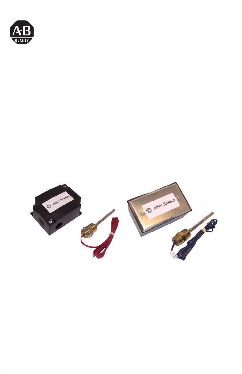
About the Immersion Temperature Transmitter
Immersion type probes are designed to measure the temperature inside pipes
carrying liquid or steam. They are to be used with a thermowell. Brass (for
non-corrosive liquids) and 304 stainless steel (for corrosive liquids) wells are
available. The immersion temperature transmitter provides 4 to 20 mA current
signal proportional to the sensed temperature and is loop powered. It is available
to fit industrial and commercial applications.
Publication 1414-IN008A-EN-P - October 2005
Page 2
2 Immersion Temperature Transmitter
Important User Information
Solid state equipment has operational characteristics differing from those of electromechanical equipment.
Safety Guidelines for the Application, Installation and Maintenance of Solid State Controls (Publication
SGI-1.1 available from your local Rockwell Automation sales office or online at
http://www.literature.rockwellautomation.com) describes some important differences between solid state
equipment and hard-wired electromechanical devices. Because of this difference, and also because of the
wide variety of uses for solid state equipment, all persons responsible for applying this equipment must
satisfy themselves that each intended application of this equipment is acceptable.
In no event will Rockwell Automation, Inc. be responsible or liable for indirect or consequential damages
resulting from the use or application of this equipment.
The examples and diagrams in this manual are included solely for illustrative purposes. Because of the many
variables and requirements associated with any particular installation, Rockwell Automation, Inc. cannot
assume responsibility or liability for actual use based on the examples and diagrams.
No patent liability is assumed by Rockwell Automation, Inc. with respect to use of information, circuits,
equipment, or software described in this manual.
Reproduction of the contents of this manual, in whole or in part, without written permission of Rockwell
Automation, Inc., is prohibited.
Throughout this manual, when necessary, we use notes to make you aware of safety considerations.
WARNING
IMPORTANT
ATTENTION
SHOCK HAZARD
BURN HAZARD
Identifies information about practices or circumstances that can cause an explosion in
a hazardous environment, which may lead to personal injury or death, property
damage, or economic loss.
Identifies information that is critical for successful application and understanding of
the product.
Identifies information about practices or circumstances that can lead to personal injury
or death, property damage, or economic loss. Attentions help you identify a hazard,
avoid a hazard and recognize the consequences.
Labels may be located on or inside the equipment (e.g., drive or motor) to alert people
that dangerous voltage may be present.
Labels may be located on or inside the equipment (e.g., drive or motor) to alert people
that surfaces may be dangerous temperatures.
Publication 1414-IN008A-EN-P - October 2005
Page 3
Immersion Temperature Transmitter 3
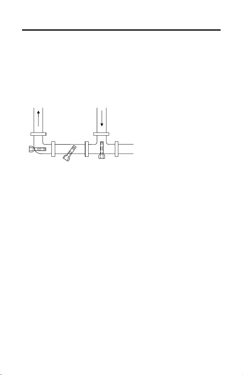
Install the Immersion Temperature Transimitter
Immersion probes must be installed into a thermowell. Mount the thermowell
either horizontally or with the open end facing down to allow any condensation to
drain and ensure that the well does not contact the inside of the pipe. For best
results, use thermal compound
(1)
inside the well and a spring loaded probe.
FLOW
Thermowell Installation Example
FLOW
Wire and Connect the Immersion Temperature Sensor
Connect the transmitter to the controller using twisted 18 to 22 AWG wire. The
transmitter requires two wires for DC 4 to 20 mA loop-powered operation. The use
of shielded cable is optional but recommended for the highest noise immunity. Do
not route signal wires in the same conduit with power cables as signal degradation
may occur. The controller Analog Input (AI) must be selected to match the
transmitter output before power is applied. The AI type must be a current input
with 250 or 500 ohm impedance. All transmitters have an operating range of 0 to
70°C (32 to 158°F). The transmitter board should not be mounted where
temperatures exceed these vaules. See the connection diagram for more details.
Typical wiring to a programmable controller is shown in the diagram.
(1) Use thermal compound from MAMAC Systems, part number A-505.
Publication 1414-IN008A-EN-P - October 2005
Page 4

4 Immersion Temperature Transmitter
2-wire RTD
Sensor
Temperature Transmitter
NEG
SEN
EXC
Loop power supply
+ 24 VDC -
Analog Current Input
ANL IN 0 +
ANL IN 0 -
ANL COM
3-wire RTD
Sensor
BLK
GRN
RED
NEG
SEN
EXC
OUT
PWR
COM
SPAN
ZERO
All two wire sensors are polarity insensitive. Three-wire RTD sensors are used in
high temperature range applications (maximum temperature > 212°F). If desired. a
three-wire sensor may be connected as two-wire by connecting together the
EXCitation and SENse lines. If used, wire splices should be made using either
buttsplices or soldering. The use of wire nuts is not recommended.
For 4 to 20 mA loop signal, only the PWR and OUT terminals are used.
High temperature probes have three wires; two wires of one color (usually black)
and the third wire a different color (usually white).
Field Calibration
The unit can be calibrated in the field by using precision resistor values equal to the
zero and span of the transmitter temperature range.
1. Disconnect the sensor from the transmitter and connect the resistor that
represents the zero value to the EXC and NEG terminals.
TIP
If the unit uses a three-wire sensor, a jumper must be placed
between EXC and SEN.
2. Adjust the ZERO pot until the desired output is achieved.
3. Connect the resistor that represents the span value to the EXC and NEG
terminals.
4. Adjust the SPAN pot until the desired output is achieved.
Publication 1414-IN008A-EN-P - October 2005
Page 5

Immersion Temperature Transmitter 5
Repeat these steps until no further adjustment is required.
Specifications
Immersion Temperature Transmitter Specifications
Specification Value
Standard Length 4”
Operating Temperature Range -40 … 105 ºC (-40 … 221 ºF)
Ambient Temperature Range 0 … 70°C (32 … 158°F)
Wiring Connections Terminal Blocks
Enclosures ABS, Metal or Weatherproof
Sensor Types 1000 Ω platinum Class A 0.15°C , Class B 0.3°C
Publication 1414-IN008A-EN-P - October 2005
Page 6

6 Immersion Temperature Transmitter
Publication 1414-IN008A-EN-P - October 2005
Page 7

Immersion Temperature Transmitter 7
Publication 1414-IN008A-EN-P - October 2005
Page 8

All other trademarks are the property of their respective holders, and are hereby acknowledged.
Publication 1414-IN008A-EN-P - October 2005 PN 40055-238-01(1)
Supersedes Publication XXXX-X.X.X - Month Year Copyright © 2005 Rockwell Automation, Inc. A ll rights reserved. Printed in t he U.S.A.
 Loading...