

Page 1
Installation Instruction
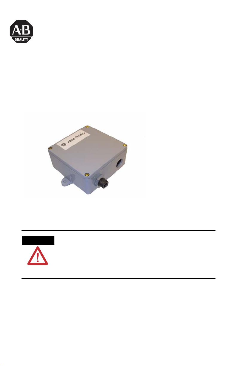
Gauge Liquid/Gas Pressure Transmitter
Catalog Number(s) 1414-CPZ10FSFAA,
1414-IPZ10FSFAA
Explosion Hazard
WARNING
Do not use in an explosive or hazardous environment, with
combustible or flammable gasses, as a safety or emergency stop
device or in any other application where failure of the product
could result in personal injury. Use electrostatic discharge
precautions during installation and do not exceed the device
ratings.
Publication 1414-IN015A-EN-P - October 2005
Page 2
2 Gauge Liquid/Gas Pressure Transmitter
Important User Information
Solid state equipment has operational characteristics differing from those of electromechanical equipment.
Safety Guidelines for the Application, Installation and Maintenance of Solid State Controls (Publication
SGI-1.1 available from your local Rockwell Automation sales office or online at
http://www.literature.rockwellautomation.com) describes some important differences between solid state
equipment and hard-wired electromechanical devices. Because of this difference, and also because of the
wide variety of uses for solid state equipment, all persons responsible for applying this equipment must
satisfy themselves that each intended application of this equipment is acceptable.
In no event will Rockwell Automation, Inc. be responsible or liable for indirect or consequential damages
resulting from the use or application of this equipment.
The examples and diagrams in this manual are included solely for illustrative purposes. Because of the many
variables and requirements associated with any particular installation, Rockwell Automation, Inc. cannot
assume responsibility or liability for actual use based on the examples and diagrams.
No patent liability is assumed by Rockwell Automation, Inc. with respect to use of information, circuits,
equipment, or software described in this manual.
Reproduction of the contents of this manual, in whole or in part, without written permission of Rockwell
Automation, Inc., is prohibited.
Throughout this manual, when necessary, we use notes to make you aware of safety considerations.
WARNING
IMPORTANT
ATTENTION
SHOCK HAZARD
BURN HAZARD
Identifies information about practices or circumstances that can cause an explosion in
a hazardous environment, which may lead to personal injury or death, property
damage, or economic loss.
Identifies information that is critical for successful application and understanding of
the product.
Identifies information about practices or circumstances that can lead to personal injury
or death, property damage, or economic loss. Attentions help you identify a hazard,
avoid a hazard and recognize the consequences.
Labels may be located on or inside the equipment (e.g., drive or motor) to alert people
that dangerous voltage may be present.
Labels may be located on or inside the equipment (e.g., drive or motor) to alert people
that surfaces may be dangerous temperatures.
Publication 1414-IN015A-EN-P - October 2005
Page 3

Gauge Liquid/Gas Pressure Transmitter 3
About the Gauge Liquid/Gas Pressure Transmitter
There are four different pressure ranges.
Range 1 2 3 4
Maximum Pressure 100 PSI 50 PSI 20 PSI 10 PSI
Install the Gauge Liquid/Gas Pressure Transmitter
The transmitter mounts on a vertical surface with the pressure ports and cable
entrance on the bottom using the two screw holes on the base of the unit. Ensure
there is enough space around the unit to make the pressure and electrical
connections. Avoid locations with severe vibrations or excessive moisture. The
enclosure has a standard ½” conduit opening and may be installed with either a
conduit coupler or a cable gland type fitting.
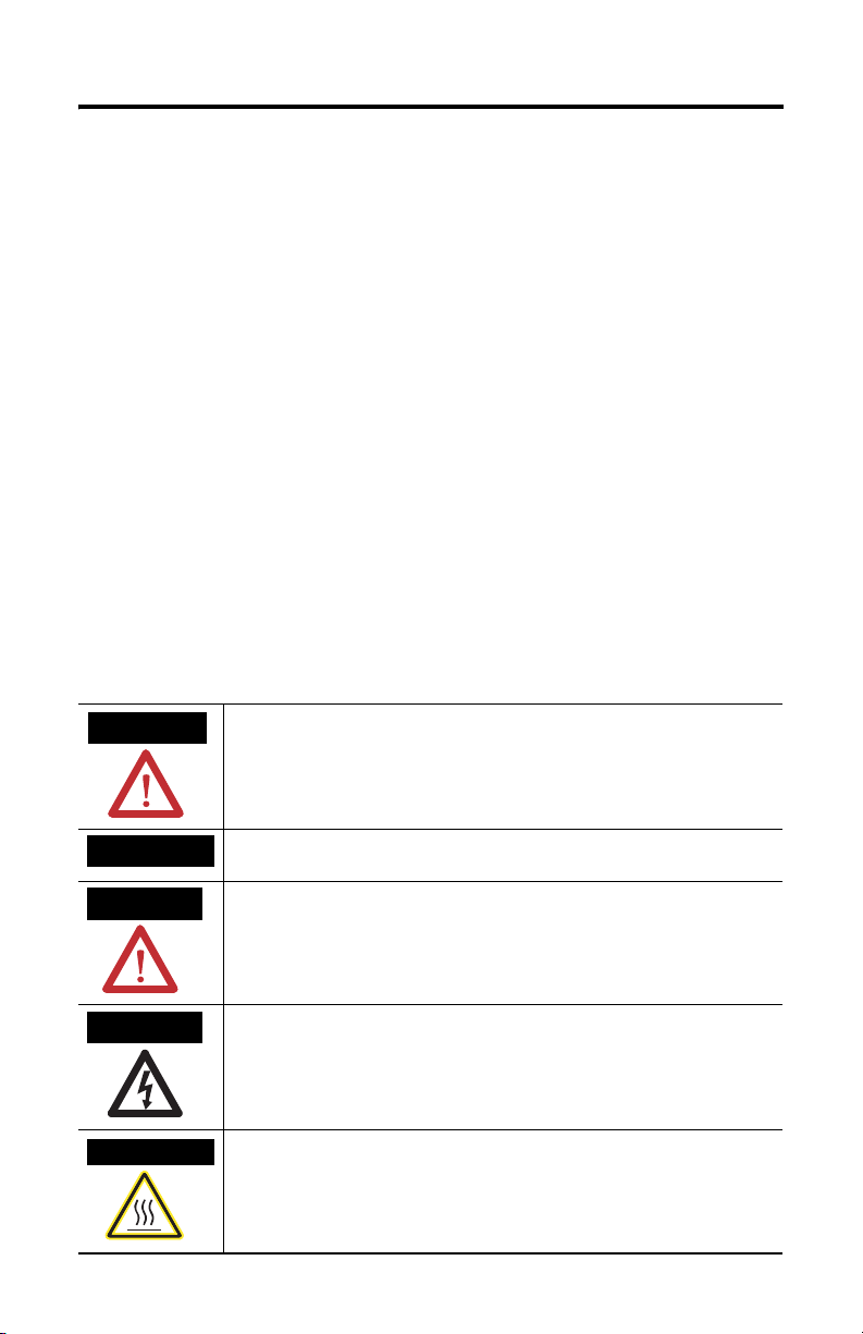
Wire and Connect the Gauge Liquid/Gas Pressure Transmitter
Use twisted-pair 18 to 22 AWG shielded wiring for all connections and do not locate
the device wires in the same conduit with wiring used to supply inductive loads
such as motors. Disconnect the power supply before making any connections to
prevent electrical shock or equipment damage. Make all connections in accordance
with national and local electrical codes.
This device is a 3-wire sourcing type transmitter. Connect the positive dc voltage or
the hot side of the ac voltage to the terminal marked PWR. The power supply
common is connected to the terminal marked COM. The device is reverse voltage
protected and will not operate if connected backwards. The analog output signal is
available on the OUT terminal. This signal is jumper selectable for either voltage or
4 to 20 mA output (factory default). In voltage mode, either 0 to 5 or 0 to 10V dc
can also be selected. These options are indicated on the circuit board.
The remote zero feature may be used by wiring a dry-contact (relay only) digital
output to the ZERO terminals. Do not apply voltage to the ZERO terminals.
Plumbing
Use an appropriately rated pressure tubing and arrange it to minimize stress on the
connections. Do not allow material to fall into the pressure ports as contamination
could damage the sensors.
Publication 1414-IN015A-EN-P - October 2005
Page 4

4 Gauge Liquid/Gas Pressure Transmitter
Configure the Gauge Liquid/Gas Pressure Transmitter
As shown on the printed circuit board diagram, push-on jumpers and switches are
used to select the output signal type, the input pressure range and several features.
The device is factory configured to operate in the 4-20 mA output mode but can be
changed to voltage mode by moving the two jumpers from the positions marked
Current to the positions marked Voltage. Always note the current jumper position
first and then move them to the new position. If the jumpers are rotated 90 degrees
and installed incorrectly the product will not work and damage may occur. In
voltage mode the output scale may be changed to either 0-5 or 0-10 Vdc by moving
the single jumper to the 5V or 10V position. The Range and Options switches can
be changed while the unit is operating. However, the output jumpers can only be
changed while the power is removed.
The jumper marked Light is not used. The input pressure range (as shown on the
product label) is set by moving the 4- position slide switch marked RANGE.
Slow damping and analog reverse functions are available by switching the
appropriate DIP switch position to ON.
• Slow Damping
This switch provides an 8-second averaging for surge dampening (normally
it is 4-seconds).
• Output Reverse
This switch reverses the output signal polarity. In reverse mode the analog
output is maximum when the pressure differential is zero and decreases as
pressure increases.
Operation
For normal operation such as 0-100 PSI, the port is used to measure a positive
pressure and 0 PSI = 4 mA and 100 PSI = 20 mA.
Calibration
With the port open to the ambient pressure (or with the port equalized at 0
pressure), press and hold the auto-zero button or provide contact closure on the
ZERO terminals for at least 3 seconds. Release the button or terminals and the
device will calculate and store the new zero point. To protect the unit from
accidental zeroing this feature is enabled only when the detected pressure on the
Publication 1414-IN015A-EN-P - October 2005
Page 5

Gauge Liquid/Gas Pressure Transmitter 5
port is less than 5% of the full range. It is not recommended that the span
calibration be performed in the field unless a high quality calibrator is available.
Optional switch settings. D efault is
Normal (switch set to off).
NO TE: The ra nge and opti ons switc h can be
cha nge d while the unit is pow er e d. Ho weve r,
the output jumpe rs ca n only be cha nge d while
the unit is unpowe red.
Remote zero switch
(optional)
ZERO
ZERO
PWR
OUT
COM
Output, Current or
Voltage.
Commo n is sha red wit h
power s upply
Power in, 24Vac/dc
Commo n is sha red wit h
output
DO NOT CONNECT POWER TO
THE ‘OUT’ TERMINAL AS THE
UNIT WILL BE DAMAGED!
Loop power supply
+ 24 V AC/DC -
Analog Current/
Voltage Input
ANL IN 0 +
ANL IN 0 -
ANL COM
Publication 1414-IN015A-EN-P - October 2005
Page 6

6 Gauge Liquid/Gas Pressure Transmitter
Specifications
Gauge Liquid/Gas Pressure Transmitter Specifications
Specification Value
Media compatibility 17-4 PH stainless steel
Input power 15 … 30 Vdc / 24 Vac nominal
Supply current @ 24 Vdc 35 mA
Output signal 4…20 mA, 0-5 or 0-10 Vdc
Proof pressure Max. 2x F.S. range
Burst pressure Max. 5x F.S. range
Accuracy +/-1 %F.S. (range 4 is +/- 2 %)
Surge damping 4 sec averaging (8 sec for slow)
Long term stability +/-0.25% typical (1 year)
Auto-zero adjust pushbutton and remote input
Sensor operating range -40 … 105 °C (-40 … 220 °F)
Operating environment 0 … 50 °C, 10 … 90 %RH n.c.
Fittings 1/8” NPT female
Enclosure 5” x 5” x 2.25” PVC NEMA 4
Publication 1414-IN015A-EN-P - October 2005
Page 7

Gauge Liquid/Gas Pressure Transmitter 7
All other trademarks are the property of their respective holders, and are hereby acknowledged.
Publication 1414-IN015A-EN-P - October 2005
Page 8

Rockwell Automation Support
Rockwell Automation provides technical information on the web to assist you in
using its products. At http://support.rockwellautomation.com, you can find
technical manuals, a knowledge base of FAQs, technical and application notes,
sample code and links to software service packs, and a MySupport feature that you
can customize to make the best use of these tools.
For an additional level of technical phone support for installation, configuration and
troubleshooting, we offer TechConnect Support programs. For more information,
contact your local distributor or Rockwell Automation representative, or visit
http://support.rockwellautomation.com.
Installation Assistance
If you experience a problem with a hardware module within the first 24 hours of
installation, please review the information that's contained in this manual. You can
also contact a special Customer Support number for initial help in getting your
module up and running:
United States 1.440.646.3223
Outside United
States
Monday – Friday, 8am – 5pm EST
Please contact your local Rockwell Automation representative for any
technical support issues.
New Product Satisfaction Return
Rockwell tests all of its products to ensure that they are fully operational when
shipped from the manufacturing facility. However, if your product is not
functioning and needs to be returned:
United States Contact your distributor. You must provide a Customer Support case number
Outside United
States
Publication 1414-IN015A-EN-P - October 2005 PN 40055-245-01(1)
Supersedes Publication XXXX-X.X.X - Month Year Copyright © 2005 Rockwell Autom ation, Inc. All rights reserv ed. Printed in the U.S.A.
(see phone number above to obtain one) to your distributor in order to
complete the return process.
Please contact your local Rockwell Automation representative for return
procedure.
 Loading...