

Page 1
Installation Instructions
Air Flow Switch
Catalog Number(s) 1414-CPN10APWAB,
1414-CPN10APQAB, 1414-CPM10APWAB
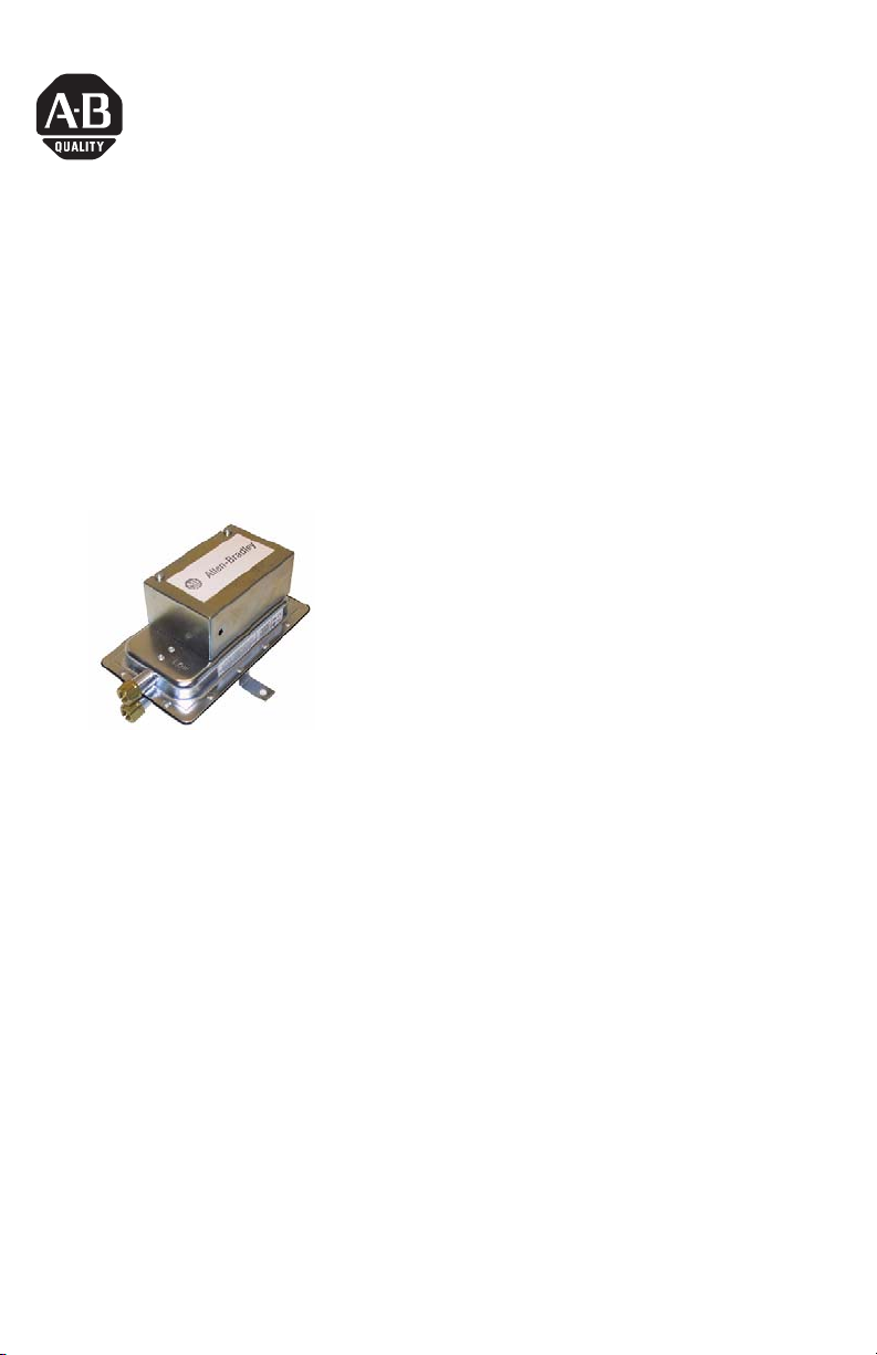
About Air Flow Switch (AFS)
The AFS is a general purpose airflow proving switch designed for HVAC and energy
management applications. It may be used to sense positive, negative or differential
air pressure.
The plated housing contains a diaphragm, a calibration spring and a snap-acting
SPDT (NC) switch.
The sample connections located on each side of the diaphragm accept a .25” OD
tubing via the integral compression and nut.
An enclosure cover guards against accidental contact with the live switch terminal
screws and the set point adjusting screw. The enclosure cover will accept a .5”
conduit connection. The AFS (1414-CPM10APWAB) has a reset button located on
the top surface of the enclosure cover.
Publication 1414-IN003A-EN-P - October 2005
Page 2
2 Air Flow Switch
Important User Information
Solid state equipment has operational characteristics differing from those of electromechanical equipment.
Safety Guidelines for the Application, Installation and Maintenance of Solid State Controls (Publication
SGI-1.1 available from your local Rockwell Automation sales office or online at
http://www.literature.rockwellautomation.com) describes some important differences between solid state
equipment and hard-wired electromechanical devices. Because of this difference, and also because of the
wide variety of uses for solid state equipment, all persons responsible for applying this equipment must
satisfy themselves that each intended application of this equipment is acceptable.
In no event will Rockwell Automation, Inc. be responsible or liable for indirect or consequential damages
resulting from the use or application of this equipment.
The examples and diagrams in this manual are included solely for illustrative purposes. Because of the many
variables and requirements associated with any particular installation, Rockwell Automation, Inc. cannot
assume responsibility or liability for actual use based on the examples and diagrams.
No patent liability is assumed by Rockwell Automation, Inc. with respect to use of information, circuits,
equipment, or software described in this manual.
Reproduction of the contents of this manual, in whole or in part, without written permission of Rockwell
Automation, Inc., is prohibited.
Throughout this manual, when necessary, we use notes to make you aware of safety considerations.
WARNING
IMPORTANT
ATTENTION
SHOCK HAZARD
BURN HAZARD
Identifies information about practices or circumstances that can cause an explosion in
a hazardous environment, which may lead to personal injury or death, property
damage, or economic loss.
Identifies information that is critical for successful application and understanding of
the product.
Identifies information about practices or circumstances that can lead to personal injury
or death, property damage, or economic loss. Attentions help you identify a hazard,
avoid a hazard and recognize the consequences.
Labels may be located on or inside the equipment (e.g., drive or motor) to alert people
that dangerous voltage may be present.
Labels may be located on or inside the equipment (e.g., drive or motor) to alert people
that surfaces may be dangerous temperatures.
Publication 1414-IN003A-EN-P - October 2005
Page 3
Air Flow Switch 3
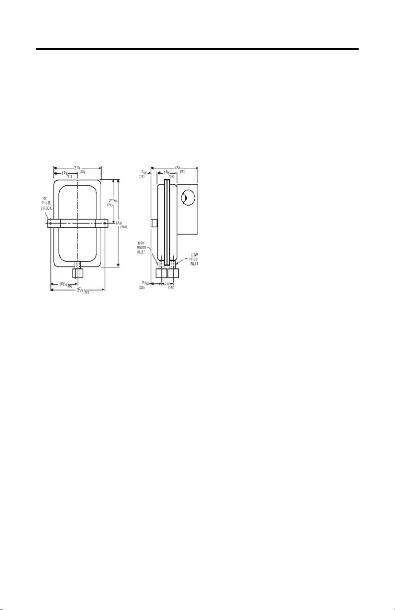
Install Air Flow Switch
Select a mounting location which is free from vibration. The AFS pressure switch
MUST be mounted with the diaphragm in any vertical plane in order to obtain the
lowest specified operating set point. Avoid mounting with the sample line
connections in the “UP” position. Surface mount via the two 3/16” diameter holes in
the integral mounting bracket. The mounting holes are 3 7/8” apart.
Figure 1 Dimensions
Air Sampling Connection
The AFS is designed to accept sample lines of .25” OD tubing by means of ferrule
and nut compression connections. Locate the sampling probe a minimum of 1.5
duct diameters down stream from the air source. Install the sampling probe as close
to the air stream as possible. The low pressure side is designated by the stamped
‘LOW’ on the housing of the diaphragm.
• Positive Pressure Only: Connect the sample line to the LOW side and the
HIGH side remains open to atmosphere.
• Negative Pressure Only: Connect the sample line to the HIGH side and the
LOW side remains open to atmosphere.
• Two Negative Samples: Connect the higher negative sample to the HIGH
side and the lower negative sample to the LOW side.
• Two Positive Samples: Connect the higher positive sample to the LOW side
and the lower positive sample to the HIGH side.
• One Positive and One Negative Sample: Connect the positive sample to the
LOW side and connect the negative sample to the HIGH side.
Publication 1414-IN003A-EN-P - October 2005
Page 4

4 Air Flow Switch
Figure 2 Alarm or Control
To prove excessive airflow or pressure
NO
C
NC
To prove insufficient airflow or pressure
NO
C
NC
Alarm
Con tr ol
Con tr ol
Alarm
Field Adjustment
From lowest operating point several turns of the adjusting screw are necessary to
engage the calibration spring. No change in set point will occur until the spring is
engaged. For higher set points continue turning screw in a clockwise direction. It
may be useful to connect a manometer in parallel with the switch when adjusting,
as the final operating point can be noted for future reference. Please see
specifications for actual ranges and set point information.
Specifications
Air Flow Switch Specifications
Specification 1414-CPN10APWAB 1414-CPN10APQAB 1414-CPM10APWAB
Sample Media Air Air Air
Mounting Position Diaphragm in any vertical
plane
Field Adjustable
Range
Switch Differential Progressive, increasing
Maximum Pressure .5” (0.03 bar) .5” (0.03 bar) .5” (0.03 bar)
Operating
Temperature Range
.05, ±.02” w.c. to 12” w.c. .05, ±.02” w.c. to 2” w.c. .40, ±.06” w.c. to 12” w.c
from approximately .02±
.01” w.c. at minimum set
point, to approximately .8”
w.c. at maximum set point.
-40°C … 82.2°C
(-40°F…180°F)
Publication 1414-IN003A-EN-P - October 2005
Diaphragm in any
vertical plane
Progressive, increasing
from 0.02± 0.01” w.c. at
minimum set point to
approximately 0.1” w.c.
at maximum set point.
-40°C … 82.2°C
(-40°F…180°F)
Diaphragm in any
vertical plane
Progressive, increasing
from approximately .06±
.01” w.c. at minimum set
point, to approximately
.8”w.c. at maximum set
point.
-40°C … 82.2°C
(-40°F…180°F)
Page 5

Air Flow Switch 5
Air Flow Switch Specifications
Specification 1414-CPN10APWAB 1414-CPN10APQAB 1414-CPM10APWAB
Life 100,000 cycles/min. at 5psi
Electrical Rating 300 va pilot duty at
Contact Arrangement SPDT SPDT SPDT
Electrical Connections Screw top terminals with
Sample Line
Connections
Automatic/Manual
Reset
max pressure each cycle
and at max electrical load.
115…277vac, 10 amp,
non-inductive, 277 vac,
60Hz.
cup washers
Ferrule and nut
compression type
connectors that accept .25”
OD rigid tubing.
Automatic Automatic Manual
100,000 cycles/min. at
5psi max pressure each
cycle and at max
electrical load.
300 va pilot duty at
115…277vac, 10 amp,
non-inductive, 277 vac,
60Hz.
Screw top term inals with
cup washers
Ferrule and nut
compression type
connectors that accept
.25” OD rigid tubing.
600 cycles/min. at 5psi
max pressure each cycle
and at max electrical
load.
300 va pilot duty at
115…277vac, 10 amp,
non-inductive, 277 vac,
60Hz.
Screw top terminals with
cup washers
Ferrule and nut
compression type
connectors that accept
.25” OD rigid tubing.
Publication 1414-IN003A-EN-P - October 2005
Page 6

6 Air Flow Switch
Publication 1414-IN003A-EN-P - October 2005
Page 7

Air Flow Switch 7
Publication 1414-IN003A-EN-P - October 2005
Page 8

All other trademarks are the property of their respective holders, and are hereby acknowledged.
Publication 1414-IN003A-EN-P - October 2005 PN 40055-233-01(1)
Supersedes Publication XXXX-X.X.X - Month Year Copyright © 2005 Rockwell Automation, Inc. A ll rights reserved. Printed in t he U.S.A.
 Loading...