

Page 1
Installation Instructions
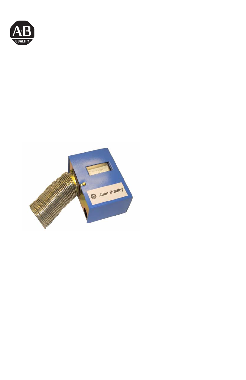
Low-limit Temperature Switch
Catalog Number(s) 1414-CLM20AHDAB,
1414-CLN20AHDAB
Install the Low-limit Temperature Switch
The switch can be mounted in any position. Avoid locations subject to excessive
vibration. On manual reset model, position control to permit convenient access to
the reset button . Use three mounting holes in rear of case for flush mounting to
duct or other flat surface. Install capillary element in horizontal serpentine pattern
across duct on downstream side of the coil so it is exposed to areas where low
temperatures will occur. Do not kink or apply excessive force to the capillary
element. Fasten capillary at sufficient points to prevent damage from air movement
or vibration.
Publication 1414-IN009A-EN-P - October 2005
Page 2
2 Low-limit Temperature Switch
Important User Information
Solid state equipment has operational characteristics differing from those of electromechanical equipment.
Safety Guidelines for the Application, Installation and Maintenance of Solid State Controls (Publication
SGI-1.1 available from your local Rockwell Automation sales office or online at
http://www.literature.rockwellautomation.com) describes some important differences between solid state
equipment and hard-wired electromechanical devices. Because of this difference, and also because of the
wide variety of uses for solid state equipment, all persons responsible for applying this equipment must
satisfy themselves that each intended application of this equipment is acceptable.
In no event will Rockwell Automation, Inc. be responsible or liable for indirect or consequential damages
resulting from the use or application of this equipment.
The examples and diagrams in this manual are included solely for illustrative purposes. Because of the many
variables and requirements associated with any particular installation, Rockwell Automation, Inc. cannot
assume responsibility or liability for actual use based on the examples and diagrams.
No patent liability is assumed by Rockwell Automation, Inc. with respect to use of information, circuits,
equipment, or software described in this manual.
Reproduction of the contents of this manual, in whole or in part, without written permission of Rockwell
Automation, Inc., is prohibited.
Throughout this manual, when necessary, we use notes to make you aware of safety considerations.
WARNING
IMPORTANT
ATTENTION
SHOCK HAZARD
BURN HAZARD
Identifies information about practices or circumstances that can cause an explosion in
a hazardous environment, which may lead to personal injury or death, property
damage, or economic loss.
Identifies information that is critical for successful application and understanding of
the product.
Identifies information about practices or circumstances that can lead to personal injury
or death, property damage, or economic loss. Attentions help you identify a hazard,
avoid a hazard and recognize the consequences.
Labels may be located on or inside the equipment (e.g., drive or motor) to alert people
that dangerous voltage may be present.
Labels may be located on or inside the equipment (e.g., drive or motor) to alert people
that surfaces may be dangerous temperatures.
Publication 1414-IN009A-EN-P - October 2005
Page 3

Low-limit Temperature Switch 3
Wire and Connect the Low-limit Temperature Switch
All wiring should comply with national and local electrical codes. An opening for
installing a connector for 1/2” conduit is provided in the bottom of the controller
case. Recommended wire size is 10 to 14 AWG solid copper wire. Use screwdriver
to loosen terminal screws. Strip wire ends 3/8” and insert into box connectors on
the switch block. Securely retighten terminal screws. For circuit testing, the DPDT
switches can be manually activated by using a screw driver to operate the test lever
located on the bottom portion of the controller scaleplate.
Switch action on decrese in temperature
(Contacts 11 to 14 and 21 to 24 Opens;
Contacts 11 to 12 and 21 to 22 Closes)
Install capillary in
horizontal pattern only
Setpoint Adjustment
The setpoint shown on the controller scaleplate is the temperature at which switch
contacts 21 to 24, 11 to 14 (DPDT) will OPEN on a fall in sensed temperature.
To change the setpoint, use a screwdriver or wrench to turn the range adjustment
screw located at the top of the spring housing. Clockwise rotation decreases the
controller setpoint. Counterclockwise rotation increases the setpoint.
Manual Reset Models
On a temperature fall to setpoint, switch contacts 21 to 24, 11 to 14 (DPDT) open
and contacts 21 to 22, 11 to 12 (DPDT) close.
The switch remains ‘locked’ in this position until the controller is manually reset by
depressing the reset button located in the top of the controller case.
The controller cannot be manually reset until the sensed temperature is at least 5ºF
(3ºC) above setpoint.
Publication 1414-IN009A-EN-P - October 2005
Page 4

Specifications
Low-limit Temperature Switch Specifications
Specification Value
Reset Action Automatic (1414-CLM20AHDAB)
Manual (1414-CLN20AHDAB)
Switch Action DPDT
Setpoint Range 1.1° to 21°C (34° to 70°F)
Differential 2.5°C (4.5°F) fixed
Comments Five capillary mounting clips supplied with each controler.
All other trademarks are the property of their respective holders, and are hereby acknowledged.
Publication 1414-IN009A-EN-P - October 2005 PN 40055-239-01(1)
Supersedes Publication XXXX-X.X.X - Month Year Copyright © 2005 Rockwell Automation, Inc. A ll rights reserved. Printed in t he U.S.A.
 Loading...