

Page 1
Installation Instructions
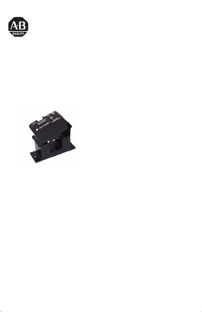
Current Switch
Catalog Number(s) 1414-CC20PTWZB
Publication 1414-IN002A-EN-P - October 2005
Page 2
2 Current Switch
Important User Information
Solid state equipment has operational characteristics differing from those of electromechanical equipment.
Safety Guidelines for the Application, Installation and Maintenance of Solid State Controls (Publication
SGI-1.1 available from your local Rockwell Automation sales office or online at
http://www.literature.rockwellautomation.com) describes some important differences between solid state
equipment and hard-wired electromechanical devices. Because of this difference, and also because of the
wide variety of uses for solid state equipment, all persons responsible for applying this equipment must
satisfy themselves that each intended application of this equipment is acceptable.
In no event will Rockwell Automation, Inc. be responsible or liable for indirect or consequential damages
resulting from the use or application of this equipment.
The examples and diagrams in this manual are included solely for illustrative purposes. Because of the many
variables and requirements associated with any particular installation, Rockwell Automation, Inc. cannot
assume responsibility or liability for actual use based on the examples and diagrams.
No patent liability is assumed by Rockwell Automation, Inc. with respect to use of information, circuits,
equipment, or software described in this manual.
Reproduction of the contents of this manual, in whole or in part, without written permission of Rockwell
Automation, Inc., is prohibited.
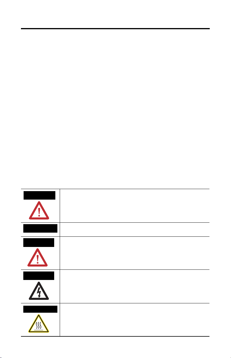
Throughout this manual, when necessary, we use notes to make you aware of safety considerations.
WARNING
IMPORTANT
ATTENTION
SHOCK HAZARD
BURN HAZARD
Identifies information about practices or circumstances that can cause an explosion in
a hazardous environment, which may lead to personal injury or death, property
damage, or economic loss.
Identifies information that is critical for successful application and understanding of
the product.
Identifies information about practices or circumstances that can lead to personal injury
or death, property damage, or economic loss. Attentions help you identify a hazard,
avoid a hazard and recognize the consequences.
Labels may be located on or inside the equipment (e.g., drive or motor) to alert people
that dangerous voltage may be present.
Labels may be located on or inside the equipment (e.g., drive or motor) to alert people
that surfaces may be dangerous temperatures.
Publication 1414-IN002A-EN-P - October 2005
Page 3

Current Switch 3
Install the Current Switch
Disconnect and lock-out all power sources during installation as severe injury or
death can result from electrical shock due to contact with high voltage conductors.
Ensure all installations are in compliance with applicable electrical codes and that
the installation is completed by qualified installers familiar with the standards and
proper safety procedures for high-voltage installation. Never rely on status
indicating devices only to determine if power is present in a conductor.
Ensure that the output circuit to be switched is within the device switch ratings as
shown in the chart, less than Switch V Max and less than Switch I Max.
Auto-range devices monitor any current over the entire range of Input I Min to
Input I Max Amps as shown in the table.
Install the Split-Core over the conductor to be monitored and close the sensor until
it latches, ensuring that the two halves are properly aligned. Operation of the
sensor will be impaired if any dirt particles prevents good contact between the core
pieces when the device is closed. Keep the sensor clean when it is opened.
Mount the switch in a suitable location using the two mounting holes in the base of
the unit.
The conductor may be looped more than once through the sensor to multiply the
sensitivity but this also divides the maximum current.
Connect the switch circuit to the two screw terminals; bear wire only. Typical
connections are shown in the wiring examples. The switchs are not polarity
sensitive and operate as a ‘dry contact’.
Using the Current Switch to control a load
M O TO R CUR RE NT W ITH TRIP POINT SET TO DETEC T A
Turn On
BR O KEN BELT OR CO UPLING
Norm al Running
Trip S etp oint
Off
Broken
Off
Publication 1414-IN002A-EN-P - October 2005
Page 4

Operation
The output switch of all devices is normally open. When the monitored current
exceeds the trip value of 1.5 Amps, the switch closes.
Specifications
Current Switch Specifications
Specification Value
Output Type Mosfet
Type AC/DC
Switch V Max 30Vac/40Vdc
I Max 500 mA
Von @ 24Vdc @ 150 mA <0.1 V
Leakage Current <25 µA
Auto Range Yes
Input I Min 1.5A
Input I Max 200A
All other trademarks are the property of their respective holders, and are hereby acknowledged.
Publication 1414-IN002A-EN-P - October 2005 PN 40055-232-01(1)
Supersedes Publication XXXX-X.X.X - Month Year Copyright © 2005 Rockwell Automation, Inc. A ll rights reserved. Printed in t he U.S.A.
 Loading...