

Page 1
Installation Instructions
Bulletin 140U / 140UE / 140M Rotary Operating Mechanism Kit
for H-Frame Circuit Breaker
(Cat 140U-H-_ _ _)
WARNING: To prevent electrical shock, disconnect from power source before installing or servicing. Follow NFPA 70E requirements. Install in suitable enclosure. Keep free from
contaminants.
Installation, adjustments, putting into service, use, assembly, disassembly, and maintenance shall be carried out by suitably trained personnel in accordance with applicable code of
practice. In case of malfunction or damage, no attempts at repair should be made.
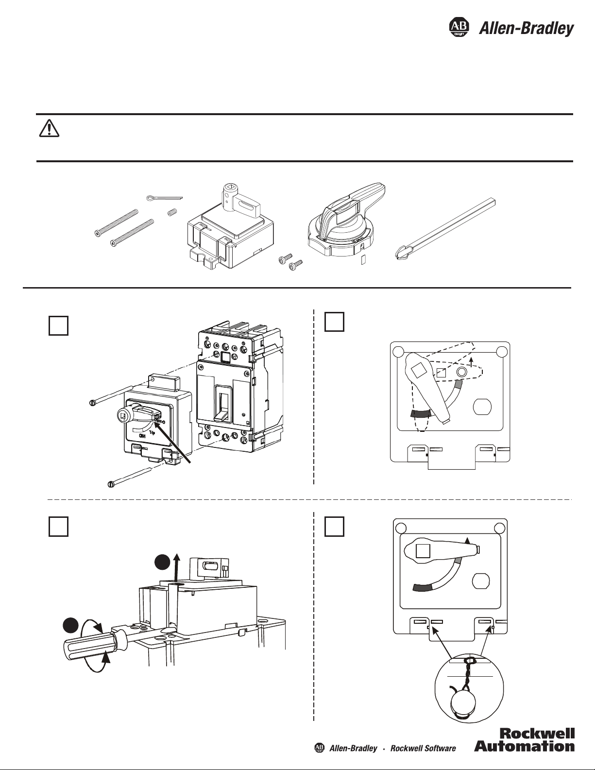
Operating Mechanism Installation
1
3 4
Place both handles
in OFF position
Remove wire tie
after installation
Remove covers to access breaker thermal adjustment and
push-to-trip switch.
2
1
Twist
2
Test for full range of motion
Trip
ON/I
ON/I
Reset
OFF/O
Reset
OFF/O
Trip
Customer supplied
safety wire
Page 2
Bulletin 140U / 140UE / 140M Rotary Operating Mechanism Kit for H-Frame Circuit Breaker
2
Operating Shaft Modication and Installation
mm
(in.)
C
C
C
1
116
-
4-19/32
-
21
C
MIN MAX
305
(12)
533
(21)
2
170.2
(6 - 11/16)
170.2
(6 - 11/16)
6.35
(1/4)
Ø 3
(Ø 1/8)
435
(17 - 1/8)
663.6
(26 - 1/8)
3
(1/8)
2
0.9 - 1.1 Nm
(8 - 10 lb-in)
3
1
3
Operating Handle Installation
1 2
1
2
Publication 140U-IN048A-EN-P - January 2013 PN-188949 DIR 10000484337 (Version 00)
Page 3

Bulletin 140U / 140UE / 140M Rotary Operating Mechanism Kit for H-Frame Circuit Breaker
Operating Handle Installation (Cont’d)
3
3
Drilling template
Gabarit de perforation
Bohrschablone
Plantilla de perforación
Modelo de perforação
Stampo preforato
2 - ø5.5 mm
2 - 7/32 in. dia.
ø 35
(ø 1-3/8)
mm
(in.)
TAPE
ø35 mm
1-3/8 in. dia.
or
ou
oder
o
PN-124909
DIR 10000207927
or
ou
oder
o
Partie frontale du panneau
Vorderseite des deckels
Parte frontale del panell
(Version 00)
2 - ø5.5 mm
2 - 7/32 in. dia.
Front of C
Frente de la tapa
Frente da tampa
Drilling template
Gabarit de perforation
Bohrschablone
Plantilla de perforación
Modelo de perforação
Stampo preforato
or
ou
Partie frontale du panneau
1.2 - 4.8
(3/64 - 3/16)
OR
oder
o
2 - ø5.5 mm
2 - 7/32 in. dia.
Front of Cover
Vorderseite des deckels
Frente de la tapa
Frente da tampa
Parte frontale del panello
ø 35
(ø 1-3/8)
31.5
(1-15/64)
63
(2-15/32)
2 - ø5.5 mm
2 - 7/32 in. dia.
ø35 mm
1-3/8 in. dia.
or
over
o
50
(1-31/32)
25
(63/64)
25
(63/64)
50
(1-31/32)
ou
oder
o
Cover Thickness:
4
/tN
(25 lb - in)
6 mm
1/4 in
(2) - ø 5.5
((2) - ø 7/32)
Front of Cover
T-20
Publication 140U-IN048A-EN-P - January 2013 PN-188949 DIR 10000484337 (Version 00)
(2) - ø 5.5
((2) - ø 7/32)
Page 4

Handle O - Open or Close Enclosure Lock handle O with Enclosure Door Interlock
2
1
1
2
Handle On - Open or Close Enclosure Handle On with Defeater Plug
2
1
1
2
3.5 mm Max.
.140 in. Max.
A
B
C
D
3 Pole Outline
4 Pole Outline
C
B
A
Allen-Bradley, Rockwell Software, and Rockwell Automation are trademarks of Rockwell Automation, Inc.
Trademarks not belonging to Rockwell Automation are property of their respective companies.
For 3 Pole Breaker Mounting:
Drill and tap four M4 x .7 holes into
mounting plate.
For 4 Pole Breaker Mounting:
Drill and tap six M4 x .7 holes into
mounting plate.
E
Breaker
3 Pole
4 Pole
96.8
(3-13/16)
Mounting Plate
A
76.2
(3)
101.6
(4)
139.7
(5-1/2)
51
(2-1/64)
114
(4-31/64)
BCD E
21.6
(27/32)
47
(27/32)
25.4
(1)
25.4
(1)
3.8
(5/32)
3.8
(5/32)
32.5
(1-9/32)
32.5
(1-9/32)
435
Max. (21” Operating Shaft)
(17 - 1/8)
663.6
Max. (12” Operating Shaft)
(26 - 1/8)
170.2
Min.
(6-11/16)
119.2
(4 - 13/32)
142.9
(5 - 5/8)
70.6
(2-25/32)
Line Side
Load Side
Mounting Plate
Publication 140U-IN048A-EN-P - January 2013
Copyright © 2013 Rockwell Automation, Inc. All Rights Reserved. Printed in USA.
DIR 10000484337 (Version 00)
PN-188949
 Loading...