

Page 1
.
CONTACT WITH ENERGIZED EQUIPMENT CAN
RESULT IN DEATH, SEVERE PERSONAL INJURY,
OR SUBSTANTIAL PROPERTY DAMAGE. DO NOT
ATTEMPT TO INSTALL OR PERFORM
MAINTENANCE ON EQUIPMENT WHILE IT IS ENERGIZED. ALWAYS VERIFY THAT NO VOLTAGE IS
PRESENT BEFORE PROCEEDING WITH THE TASK,
AND ALWAYS FOLLOW GENERALLY ACCEPTED
SAFETY PROCEDURES.
ALLEN-BRADLEY IS NOT LIABLE FOR THE MIS-
APPLICATION OR MISINSTALLATION OF ITS
PRODUCTS.
The user is cautioned to observe all recommendations,
warnings, and cautions relating to the safety of personnel and equipment as well as all general and local health
and safety laws, codes, and procedures.
The recommendations and information contained herein
are based on Allen-Bradley experience and judgement,
but should not be considered to be all-inclusive or
covering every application or circumstance which may
arise. If any questions arise, contact Allen-Bradley for
further information or instructions.
1. INTRODUCTION
WARNING
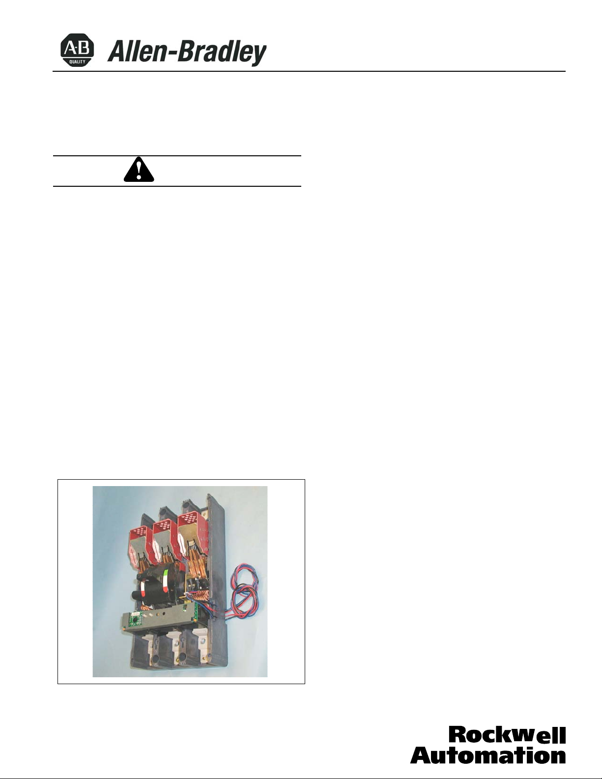
Fig. 1-1. Alarm Switch Installed in N-Frame Breaker
N-Frame Circuit Breaker
Installation Instructions for Alarm Switch and
Alarm Auxiliary Switch Combination
General Information
The alarm (signal)/lockout switch (ASL switch) (Fig. 1-1)
is attached to a plug-in module available in the following
combinations:
•
One or two ASL switches
•
One auxiliary switch and one ASL switch
•
Two auxiliary switches and one ASL switch
The plug-in module is mounted in slots in the top of the
trip unit and occupies the accessory mounting cavity in
the circuit breaker frame. The ASL switch provides
remote signaling and interlocking when the circuit breaker trips; it consists of one or two single-pole, doublethrow (SPDT) switches. Each SPDT switch has a make
(alarm) and a break (lockout) contact; it is mounted so
that the switch actuator arm is controlled by the position
of the circuit breaker crossbar.
When the circuit breaker is in the ON or OFF position,
the crossbar allows the make contact to open and the
break contact to close. When the circuit breaker is in the
tripped position, the make contact is closed and the
break contact is open. Any type of trip operation (for
example, automatic trip, shunt trip, or undervoltage
release) actuates the ASL switch.
The auxiliary switch(es) in the combination accessory
indicates circuit breaker contacts status, and is used for
remote signaling and system interlocking purposes.
Each SPDT switch has one "a" and one "b" contact. The
plug-in module is mounted in slots in the top of the trip
unit; it occupies the accessory cavity in the circuit breaker frame, and is positioned so that the switch actuator is
operated by the crossbar. When the crossbar is in the
contacts-closed position, the "a" contact of each SPDT
switch is closed and the "b" contact is open. When the
crossbar is in the tripped or contacts-open position, the
"a" contact is open and the "b" contact is closed.
Table 1-1 lists electrical rating data for the auxiliary switch.
For this publication, the term circuit breaker shall also
include molded case switch and motor circuit protector.
Bul. 140U
40752-094 (1) Effective 04/02
Page 2
Where local codes and standards permit and UL listing
is not required, internal accessories can be field
installed in sealed circuit breakers. In this case, UL list
ing becomes invalid and the label should be removed.
File E7819.
Before attempting to install the ASL switch or accessory combination, check that the catalog number is
correct as ordered and that the rating of the accessory(s) satisfies the job requirements.
Depending on the model ordered, connections for the
ASL switch and auxiliary switch contacts are in one of
four forms. The standard wiring configuration is pigtail
leads exiting the rear of the base directly behind the
accessory. Optional configurations include a terminal
block mounted on the same side of the base as the
accessory, leads exiting the side of the base where the
accessory is mounted, and leads exiting the rear of the
base on the side opposite the accessory. The 18-inch
long pigtail leads are color coded for identification; identification labels are provided for pigtail leads and terminal block points. For allowable locations of all accessories, refer to Selection Guide.
No more than three pigtail leads can be routed
through the rear trough in the circuit breaker base.
This instruction leaflet (IL) gives detailed procedures for
installing the ASL switch and ASL switch/auxiliary switch
combination (accessory combination).
Table 1-1. Alarm (Signal)/Lockout and Auxiliary Switch
Electrical Rating Data ①➁➂
Maximum Freq Maximum Dielectric
Voltage Current Withstand
(V) (A) Voltage (V)
600 50/60 Hz 6 2500
125 DC 0.5➃
250 DC 0.25➃
① Endurance- 400 electrical operations plus 5600
mechanical operations
➁ Pigtail wire size - No. 18 AWG (0.82 mm)
➂ Terminal block is listed for use with one or two No. 18 to
No. 14 AWG solid or stranded copper wires. Torque is
7 Ib-in (0.8 N.m)
➃ Non-inductive load
2. INSTALLATION
The ASL switch(es) and accessory combination can be
field-installed in N-Frame circuit breakers.
Page 2
NOTICE
NOTICE
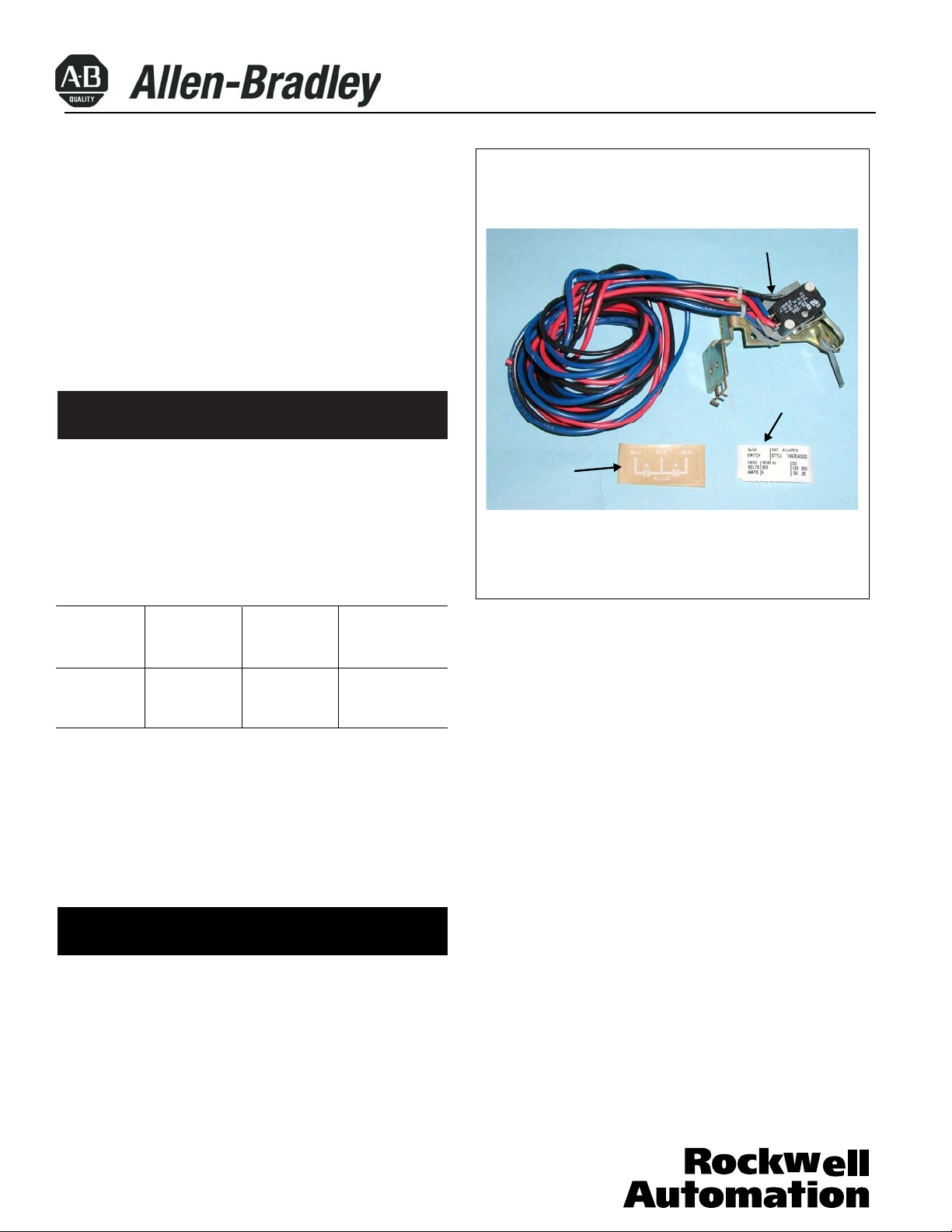
Fig. 2-1. Alarm (Signal) Lockout Switch Kit
Plug-in Module with
Pigtail Leads (single
ASL Switch Shown)
Accessory
Identification
Label
Connection
Diagram Label
(Pigtail Lead
Label Shown)
The ASL switch (shown in kit form in Fig. 2-1) and accessory
sory combination, is installed in the right or left accessory
mounting cavity of a 2-, 3-, or 4-pole circuit breaker. An
auxiliary switch must be installed in the circuit breaker
tem. To install the auxiliary switch, perform the following
before the circuit breaker is mounted in an electrical sys-
procedures:
40752-094 (1) Effective 04/02
Page 3
A circuit breaker that is mounted in an electrical
system must be removed to install the accessory.
To ensure correct accessory installation, the circuit
breaker must be placed on a horizontal surface.
General Installation
THE VOLTAGES IN ENERGIZED EQUIPMENT CAN
CAUSE DEATH OR SEVERE PERSONAL INJURY.
BEFORE REMOVING A CIRCUIT BREAKER
INSTALLED IN AN ELECTRICAL SYSTEM, MAKE
SURE THE CIRCUIT BREAKER IS SWITCHED TO
THE OFF POSITION AND THERE IS NO VOLTAGE
PRESENT WHERE WORK IS TO BE PERFORMED.
SPECIAL ATTENTION SHOULD BE PAID TO
REVERSE FEED APPLICATIONS TO ENSURE NO
VOLTAGE IS PRESENT.
Steps 2-1 through 2-8 and 2-11 through 2-17 are for
general installation and apply to the ASL switch and
the accessory combination. Step 2-9 covers installation of the ASL switch. Step 2-10 covers installation
of the accessory combination.
For new circuit breaker installation, the trip unit must
be installed in circuit breaker before attempting to
install an ASL switch or accessory combination.
2-1. Switch circuit breaker to OFF position.
2-3. Press PUSH-TO-TRIP button to trip operating
mechanism and check handle moves to trip position with
2-4. Remove circuit breaker cover screws and covers.
Page 3
For all combinations of accessories, leads from the
inner accessory switch must go to the wiring trough
or triple combination, leads from the outer accessory
switch must go to the center trough . PigtaiI leads exiting in this manner should be eased through trough as
mounting bracket is inserted into trip unit retaining
slots. Use center trough also for leads exiting the side
LEADS SHOULD BE FORMED AND ROUTED TO
CLEAR ALL MOVING PARTS WHEN ACCESSORY IS
PROPERLY INSTALLED. LEADS COULD BE DAMAGED IF IN CONTACT WITH MOVING PARTS.
bination, leads from the outer accessory switch must
go to center trough.
Alarm (Signal)/Lockout Switch Installation
a. Turn ASL switch mounting bracket to line up with slots in
trip unit.
NOTICE
WARNING
NOTICE
NOTICE
NOTICE
CAUTION
NOTICE
nearest the line end of the circuit breaker. For a double
of the circuit breaker.
2-5. Route wiring to meet installation requirements (see
Fig. 2-2
).
2-2. Disconnect and remove circuit breaker from instal-
lation and terminal connections.
white colored indicator visible in escutcheon window.l
For all combinations of accessories, leads from inner
accessory switch must go to the wiring trough nearest
line end of circuit breaker. For a double or triple com-
2-6. Insert the ASL switch as described in the following
steps (see Fig. 2-3
):
40752-094 (1) Effective 04/02
Page 4

Accessory labels show connection diagram for ASL
switch and/or auxiliary switch contacts. Pigtail leads
are color coded red, black, and blue. Be sure that
accessory terminal marking label is attached correctly
to leads and agrees with related leads at accessory.
2-10. Test ASL switch(es) by connecting continuity tester
or ohmmeter across pigtail leads or terminal block connections. Check continuity as follows:
a. Circuit breaker handle OFF
Check that make contact(s) are open and break contact(s)
are closed.
b. Circuit breaker handle ON
Check that make contact(s) are open and breaker contact(s) are closed.
NOTICE
Page 4
b. Slide ASL switch mounting bracket into slots until
retaining clip snaps into trip unit. For terminal block
assemblies, slide terminal block into mounting slot on
side of base as plug-in module is being positioned.
c. If required, complete routing of leads to opposite side
through rear wiring trough.
d. For double ASL switch with pigtail leads, attach wire
marking labels to bundle of three leads for each switch.
(Markers designated 1 and 2 are provided.)
e. For ASL/auxiliary switch accessory combinations with
pigtail leads, attach wire marking labels to bundle of
three leads for each switch. (Markers designated A and
B are provided if required. )
Accessory Combination Installation
2-7. Install accessory combination switch as described
in the following steps (see Fig. 2-4):
a. Turn accessory combination mounting bracket to line
up with slots in trip unit.
b. Slide accessory combination mounting bracket into
slots until retaining clip snaps into trip unit. For terminal
block assemblies, slide terminal block into mounting slot
on side of base as accessory combination is being positioned.
c. If required, complete routing of leads to opposite side
through rear wiring trough.
d. For double auxiliary switch pigtail leads, attach wire
marking labels to bundle of three leads for each switch.
(Markers designated 1 and 2 are provided if required.)
WHEN INSTALLING CIRCUIT BREAKER MAIN
COVER, MAKE SURE THAT ALL INTERNAL PARTS
ARE IN PLACE:
•
ALL LEADS ARE CLEAR OF THE COVER.
2-8. With circuit breaker handle in TRIPPED position
and acces- sory pigtail leads (if used) routed as
required, install circuit breaker covers. Secure with panhead cover screws. Torque large screws to 35-45 Ib-in.
(4.0-5.0 N.m.) and small screws to 24-30 lb-in (2.7-3.4 N.m).
2-9. Place accessory labels (supplied with kit) on circuit breaker (see Fig. 2-5).
CAUTION
c. Press PUSH-TO-TRIP button
Check that make contact(s) are closed and break
contact(s) are open.
d. If ASL switch(es) fails test, make sure that module is
properly seated in trip unit slots. If problem persists. contact
Allan-Bradley.
2-11. Test auxiliary switch(es) (when supplied). Connect
continuity tester or ohmmeter across pigtail leads or termi-
nal block connections. Check continuity as follows:
a. Circuit breaker handle OFF
"a" contacts(s)- open
"b" contact(s)- closed.
b. Circuit breaker handle ON
"a" contact(s) - closed
"b" contact(s) - open
c. Press PUSH-TO-TRIP button
"a" contact(s)- open
"b" contact(s) - closed
40752-094 (1) Effective 04/02
Page 5
Page 5
d. If auxiliary switch(es) fails test, make sure that auxiliary
switch(es) module is properly seated in trip unit slots. If
auxiliary switch(es) appears to be correctly installed and
the problem persists, contact Allen-Bradley.
2-12. Install circuit breaker.
2-13. Connect accessory leads as required (see Fig. 2-6).
Allen-Bradley assumes no responsibility for malfunctioning accessories installed improperly by the customer.
Rear Exiting Leads
(Preferred)
Terminal Back
Opposite-Side
Exiting Leads
Side Exiting Leads
Figure 2-2 Accessory Wiring Options
ASL
Switch
ASL
Switch
Actuator
Arm
Figure 2-3 Alarm (Signal) Lockout Switch Installation
Figure 2-4 Accessory Combination Installation
Auxiliary
Switch
ASL
Switch
Actuator
Arm
40752-094 (1) Effective 04/02
Page 6

Page 6
Modification
Label
Pigtail
Connection
Diagram
(When Used)
Accessory
Identification
Label
Terminal
Block
Connection Diagram
Label (When Used)
Figure 2-5 Preferred Mounting Locations for Accessory
Nameplate Labels
Figure 2-6 Alarm (Signal)/Lockout Switch - Auxiliary
Switch Connection Diagram
Pigtail Leads
ALS Switch
Blue
Make
(Alarm)
Break
(Lockout)
Red
Blue
Make
(Alarm)
Black
Break
(Lockout)
Red
Terminal Block
Leads are Bundled
and Tagged “B”
Leads are Bundled
and Tagged “A”
Red
a
Black
b
Blue
ASL Switch
Auxiliary Switch
40752-094 (1) Effective 04/02
Printed in U.S.A./TQC
 Loading...