

Page 1
40752-090(1) Effective 5/02
N-Frame Circuit Breakers
Instruction Leaflet for Drilling and Assembling Flex-Cable Handle Mechanism
DO NOT ATTEMPT TO INSTALL OR PERFORM
MAINTENANCE ON EQUIPMENT WHILE IT IS ENERGIZED. SEVERE PERSONAL INJURY, DEATH, OR
SUBSTANTIAL PROPERTY DAMAGE CAN RESULT
FROM CONTACT WITH ENERGIZED EQUIPMENT.
ALWAYS VERIFY THAT NO VOLTAGE IS PRESENT
BEFORE PROCEEDING WITH THE TASK, AND
ALWAYS FOLLOW GENERALLY ACCEPTED
SAFETY PROCEDURES.
ALLEN-BRADLEY IS NOT LIABLE FOR THE
MISAPPLICATION OR MISINSTALLATION OF ITS
PRODUCTS.
The user is cautioned to observe all recommendations,
warnings and cautions relating to the safety of personnel and equipment as well as all general local health
and safety laws, codes and procedures.
The recommendations and information contained herein
are based on Allen-Bradley experience and judg-
ment, but should not be considered to be all-inclusive or
covering every application or circumstance which may
arise. If any questions arise, contact Allen-Bradley for
further information or instructions.
!
WARNING
GENERAL INFORMATION
The Shaft Handle M
echanism provides a means of externally operating the circuit breaker and can be applied to
enclosures of varying heights and depths. The handle
can be used with NEMA 1, 3R, and 12 enclosure applications, plus NEMA 4 and 4x applications, depending on
the accessory components selected. An operating handle, flexible shaft, and mechanism are required for standard applcation. Three lengths of shafts are available for
use with the range of depths of various enclosures (4’, 5’,
and 6’). When selecting the length of the Flexible Shaft,
ensure Minimum Bending Radius of 5 inches is maintained to operate properly.
WHEN INSTALLING A NEW HANDLE MECHANISM,
OR A NEW CIRCUIT BREAKER AND HANDLE
MECHANISM IN AN EXISTING ELECTRICAL SYSTEM, MAKE SURE THERE IS NO VOLTAGE PRESENT WHERE WORK IS TO BE PERFORMED. SPECIAL ATTENTION SHOULD BE PAID TO REVERSE
FEED APPLICATIONS TO ENSURE NO VOLTAGE IS
PRESENT. THE VOLTAGE IN ENERGIZED EQUIPMENT CAN CAUSE DEATH OR SEVERE PERSONAL
INJURY.
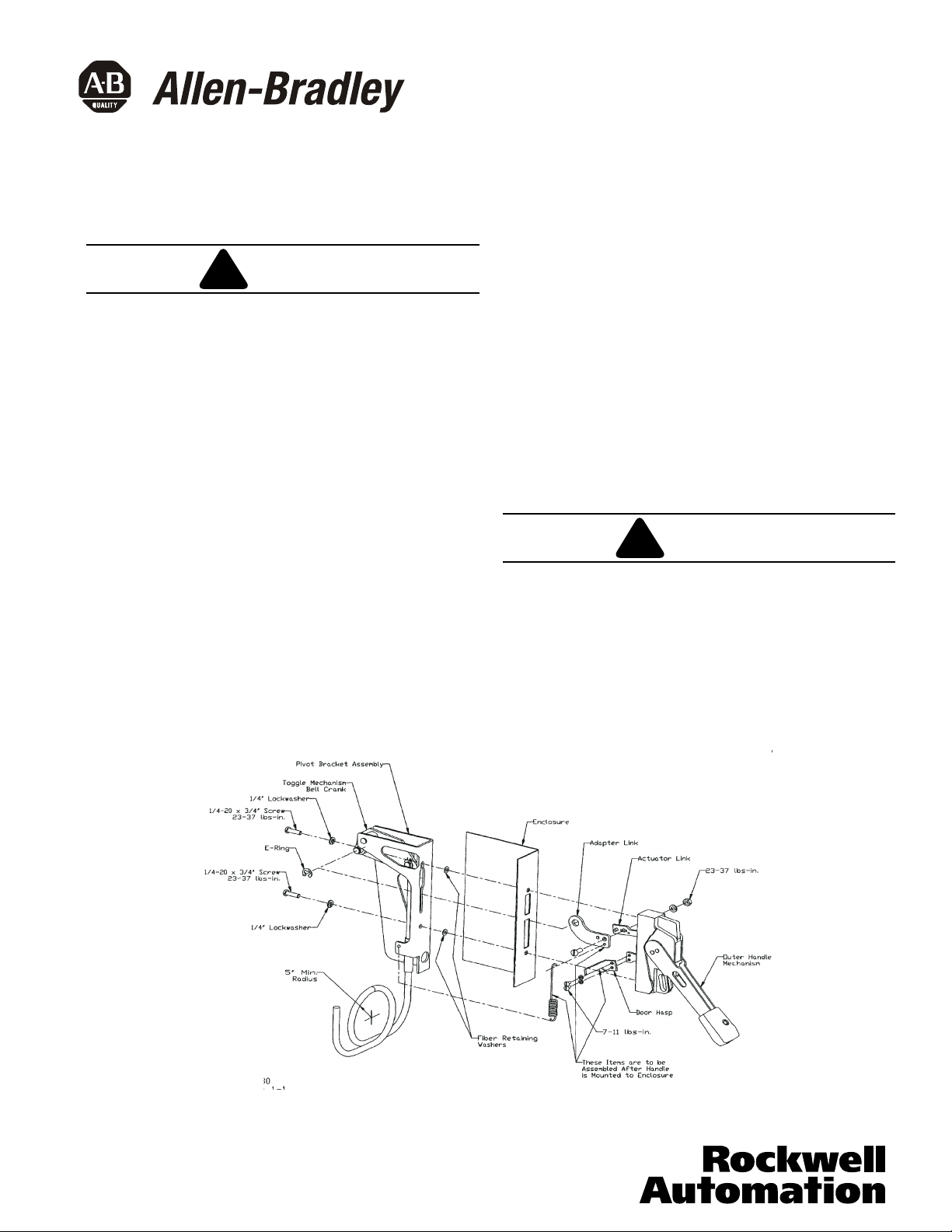
Figure 1-1 Pivot Bracket and Outer Handle Mechanism Assembly
!
WARNING
Bul. 140U
Page 2
Page 2
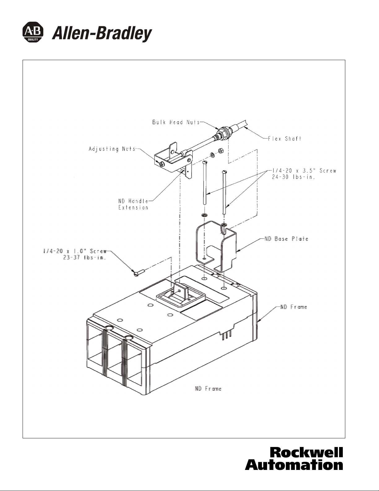
Figure 1-2 Mechanism Assembly
40752-090(1) Effective 5/02
Page 3

INSTALLATION
1.Remove the two 1/4-20 x 3/4" screws and
lockwashers from the outer handle mechanism.
kit. Place each screw and lockwasher though
the pivot bracket assembly Thread the fiber
retaining washers enclosed with the flex parts kit
onto the 1/4-20 x 3/4" screws. See Figure 1-1.
2.Install mechanism handle to enclosure by
placing the outer handle mechanism with gasket
over the enclosure cutout. Insert the mounting
screws from the pivot bracket assembly into
the outer handle mechanism.
3.Attach the adapter link to the handle actuator
Link and secure with 1/4-20 screw, lockwasher
and nut, Provided. See Fig 1-3.
6. Mount breakers Line end to enclosure using the
mounting hardware provided in the hardware kit.
the load end of the breaker per the following:
ND: Attach the load end of the bracket to the enclosure using hardware from the kit. Attach the base plate
to the circuit breaker using the ¼-20 x 3.5" screws and
¼" lockwashers enclosed in the parts kit at the load end
screws located between the trip unit and the two load
end mounting holes.
See fig 1-2 for illustration.
8. Place the outer handle mechanism in the full ON
position and the circuit breaker in the ON position.
Handle to the ON position. Place the handle extension
assembly onto the breaker handle and secure as
Shown on fig 1-2.
9. Locate bulk head nuts of the flexible shaft over the
groove of the base plate and tighten.
Page 3
10. Actuate the outer handle positions (ON,OFF,
RESET). If minor adjustments are necessary,
refer to the following adjustment checklist and
Figure 1-2.
Install door hardware (supplied); refer to
Adjustment Checklist
Situation:
tripped.
Adjustment:
Loosen the ¼-28 adjusting nut that is closest to the black
cap and turn towards the cap approximately 1.5-2 turns.
to the handle extension and inner adjusting nut.
Re-check for the ON, OFF, and RESET position. If not
successful, repeat procedure. If still not successful, and
the bulk head nuts, and shift the cable towards the load
end of the breaker. Re-tighten the bulk head nuts.
successful , repeat the beginning steps.
Situation:
Breaker resets after tripping, but does not turn ON.
referenced on Figure 1-3.
Adjustment:
Loosen the ¼-28 adjusting nut that is located on the end
approximately 1.5-2 turns. Re-tighten the adjusting nut
that is closest to the black cap to the handle extension
and RESET position. If not successful, and the adjusting
loosen the bulk head nuts, and shift the cable towards the
line end of the breaker. Re-tighten the bulk head nuts.
Re-check for the ON, OFF and RESET position. If not
successful, repeat the beginning steps.
If any other adjustment problems should arise, contact
your local Allen-Bradley representative.
4. Attach the E-Ring that attaches the adaptor
link to the toggle mechanism. See Fig 1-1.
5. Drill and tap the mounting holes for the circuit
breaker. See breaker frame instruction leaflet for
the drilling pattern.
NOTICE
Be certain that there is a 5 inch minimum
clearance between the load end of the breaker
and wall of the enclosure for the flex shaft.
reference figure 1-4.
Breaker turns ON and OFF, but will not RESET when
Re-tighten the adjusting nut that is on the end of the shaft
the adjusting nut is bottomed out onto the shaft, loosen
Re-check for the ON, OFF and RESET position. If not
7. Attach the base plate and mounting hardware to
of the breaker after removing the (2) load end cover
You must Release the Door Interlock to move the
of the shaft and turn towards the end of the shaft
and the outer adjusting nut. Re-check for the ON, OFF
nut on the end of the shaft is two threads from the end,
40752-090(1) Effective 5/02
Page 4
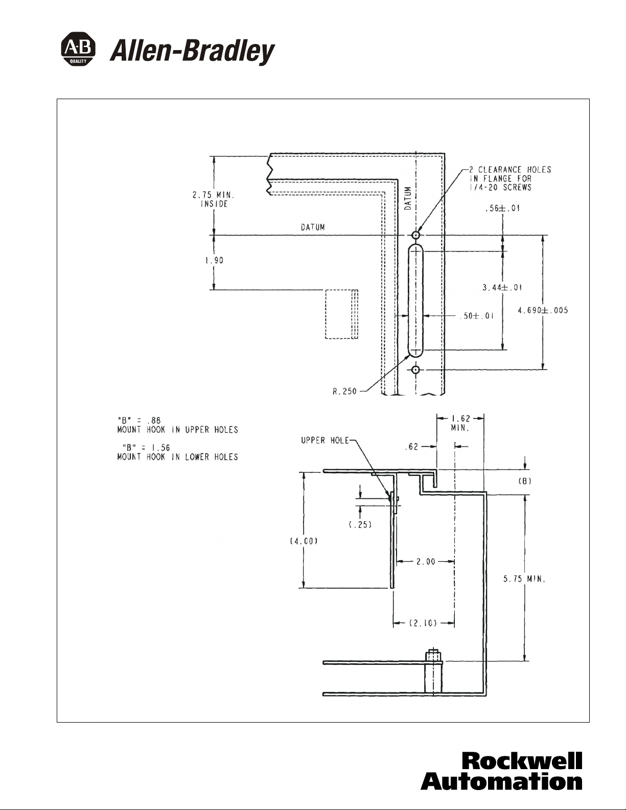
Figure 1-3 Flange Drilling Plan For Handle and Interlock Blade Mounting Dimensions
AMT-Vari-Depth Handle Mechanisms (Dimensions in Inches)
Outline and Drilling Plans
For Enclosure Door Interlock Assembly
Page 4
40752-090(1) Effective 5/02
Printed in U.S.A./TQC
 Loading...