

Page 1

Bul. 140U
K-Frame Circuit Breaker
Instruction Leaflet for Alarm Switch and Alarm /Auxiliary Switch Combination
a
DO NOT ATTEMPT TO INSTALL OR PERFORM MAIN
TENANCE ON EQUIPMENT WHILE IT
DEATH, SEVERE PERSONAL INJURY,
TIAL PROPERTY DAMAGE CAN RESULT FROM CON
TACT WITH ENERGIZED EQUIPMENT. ALWAYS
VERIFY THAT NO VOLTAGE
PROCEEDING WITH THE TASK, AND ALWAYS FOL
LOW GENERALLY ACCEPTED SAFETY PROCE
DURES.
ALLEN-BRADLEY
PLICATION OR MISINSTALLATION
UCTS.
The user is cautioned
warnings, and cautions relating to the safety of personnel
and equipment as well as all general and local health and
safety laws, codes, and procedures.
The recommendations and information contained herein
are based on Allen-Bradley experience and judgement,
but should not be considered to be all
ing every application or circumstance which may arise. If
any questions arise, contact Allen-Bradley for further
information or instructions.
1.
INTRODUCTION
WARNING
IS
ENERGIZED.
OR
SUBSTAN
IS
PRESENT BEFORE
IS
NOT LIABLE FOR THE MISAP
OF
ITS PROD
to
observe all recommendations,
-
inclusive or cover
-
-
-
-
-
-
-
-
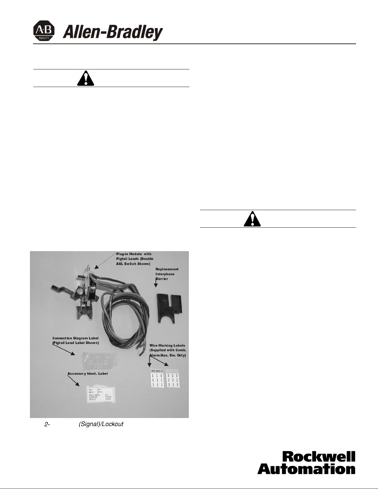
Fig.
I
-
1.
Alarm (Signal)/iockout
K-Frame Circuit Breaker
switch has a make (alarm) and a break (lockout) contact;
it is mounted so that the switch actuator arm is controlled
by the circuit breaker operating mechanism cradle. The
actuator arm extends past the operating mechanism cra
dle; therefore, only one plug-in module containing an
switch or switches can be used in a circuit breaker.
Switch
Installed in
-
ASL
General Information
The alarm (signal)/lockout switch
-
attached to a plug
combinations (see Fig.
One or two ASL switches
One auxiliary switch and one ASL switch
The plug
trip unit and occupies the accessory mounting cavity in
the circuit breaker frame.
The
ing when the circuit breaker trips; it consists of one or two
single
-
in module is mounted in slots in the top of the
ASL
switch provides remote signaling and interlock
-
pole, double-throw (SPDT) switches. Each SPDT
40752-035(1)
in module available in the following
1-1):
Effective 3/02
(ASL
switch) is
ON
or
When the circuit breaker is in the
cradle holds the make contact open and the break con
tact closed. When the circuit breaker is in the tripped
position, the make contact is closed and the break con
tact is open. Any type
matic trip, shunt trip, or undervoltage release) actuates
the
ASL
switch.
The auxiliary switch in the combination accessory indi
cates circuit breaker contacts status and is used for
remote signaling and system interlocking purposes. Each
SPDT switch has one “a” and one
module mounts in the accessory mounting cavity of the
circuit breaker
against the molded crossbar. When the molded crossbar
is in the contacts
SPDT switch is closed and the
so
of
trip operation (for example, auto
that the switch actuator arm rests
-
closed position, the “a” contact of each
“b” contact is open. When
OFF
“b” contact. The plug-in
position, the
-
-
-
-
Page 2

Page 2
the molded crossbar is in the tripped or contacts-open
‘(a”
position, the
closed.
Table 1-l lists electrical rating data for the ASL switch
and auxiliary switch.
Table l-1. Alarm
Auxiliary Switch Electrical Rating
Maximum Freq.
Voltage
P)
600
125
250
0
Endurance - 1000 electrical operations plus
5000 mechanical operations
0
Pigtail wire size -No. 18 AWG (0.82
0
Terminal block is listed for use with one or two
No. 18 to No. 14 AWG solid or stranded
copper wire. Torque is 7 lb-in (0.8 N.m)
@
Non-inductive load
contact is open and the “b” contact is
(Signal)/Lockout
Current
(A)
50/60
Hz
DC
DC
6
0.50
Switch and
Data@@@
Maximum Dielectric
Withstand
Voltage (V)
2500
0.250
mm2)
This Instruction Leaflet (IL) gives detailed procedures for
installing the ASL switch and ASL switch/auxiliary switch
combination (accessory combination.)
2. INSTALLATION
Note: The ASL
tion can be field-installed in K-Frame circuit
breakers.
Before attempting to install the ASL switch or acces-
sory combination, check that the catalog number is
correct and the rating of the accessory(s) satisfies
the job requirements.
The ASL switch and accessory combination, as shown in
kit form in Fig. 2-1, can be installed in the right or left
accessory mounting cavity of a 2-,3-, or 4-pole circuit
breaker. An ASL switch or accessory combination must
be installed in the circuit breaker before the circuit
breaker is mounted in an electrical system. To install the
ASL switch or accessory combination, perform the following procedures:
Note: A circuit breaker that is mounted in an electrical system must be removed to install the accessory.
To ensure correct accessory installation, the circuit
breaker must be placed on a horizontal surface.
switch(es)
and accessory combina-
Depending on the model ordered, connections for the
ASL switch and auxiliary switch contacts are in one of
four forms. The standard wiring configuration is pigtail
leads exiting the rear of the base directly behind the
accessory. Optional configurations include a terminal
block mounted on the same side of the base as the
accessory, leads exiting the side of the base where the
accessory is mounted, and leads exiting the rear of the
base on the side opposite the accessory, The
long pigtail leads are color coded for identification; identi-
fication labels are provided for pigtail leads and terminal
block points. For allowable locations of all accessories,
refer to Product Selection Guide.
Note: No more than three pigtail leads can be routed
through the rear trough in the circuit breaker base.
When the walking beam interlock is used with the circuit breaker, the rear trough cannot be used for
accessory pigtail leads.
18-inch
40752-035(1) Effective 3/02
Page 3
Page 3
General Installation
a
BEFORE REMOVING A CIRCUIT BREAKER
INSTALLED IN AN ELECTRICAL SYSTEM, MAKE
SURE THE CIRCUIT BREAKER IS SWITCHED TO THE
OFF POSITION AND THERE IS NO VOLTAGE
PRESENT WHERE WORK IS TO BE PERFORMED.
SPECIAL ATTENTION SHOULD BE PAID TO
REVERSE FEED APPLICATIONS TO ENSURE NO
VOLTAGE IS PRESENT. THE VOLTAGES IN ENERGIZED EQUIPMENT CAN CAUSE DEATH OR SEVERE
PERSONAL INJURY.
Note: Steps 2-1 through 2-11 and 2-14 through 2-19
are for general installation and apply to the ASL
switch and the accessory combination. Step 2-12
covers installation of the ASL switch. Step 2-13 covers installation of the accessory combination.
For new circuit breaker installation, the trip unit must
be installed in the circuit breaker before attempting
to install an ASL switch or accessory combination.
WARNING
Note: Molded case switch trip units are not equipped
with a Push-to-Trip button. For molded case
switches, omit step 2-2.
2-2.
2-3.
2-4.
Note: To install accessory, circuit breaker must be in
tripped position.
2-5.
DO NOT RESET CIRCUIT BREAKER AFTER MOLDED
HANDLE IS REMOVED. CRADLE RESET PIN MAY
FLY OUT AND CAUSE INJURY IF MECHANISM IS
TRIPPED.
Press PUSH-TO-TRIP button to trip operating
mechanism.
Disconnect and remove circuit breaker from installation and terminal connections.
Remove cover screws and cover.
For high instantaneous trip-type molded case
switches, locate recessed hole in either
of the trip unit outer poles. (Fig 2-2). Push a
fine point implement in one hole to trip the molded
case switch.
a
WARNING
2-
1.
A/arm
(Signal)/Lockout
2-l. Switch circuit breaker to OFF position.
Switch Kit
2-7.
Remove handle-retaining screws and molded han-
dle from handle arm. (See Fig. 2-3.)
2-8.
Remove interphase barrier between center pole
and pole in which accessory is to be mounted.
(See Fig. 2-3.)
Install replacement interphase barrier supplied with
2-9.
kit in base. (See Fig. 2-3.)
Note: Before the next step, be sure that replacement
interphase barrier has been installed in correct
accessory cavity side, and that cradle reset pin has
not fallen out of retaining-slot in handle arm.
2-10. Put molded handle on handle arm, and install
retaining screws.
Note: For all combinations of accessories, leads
from inner accessory switch must go to the wiring
trough nearest line end of circuit breaker. For a double combination, leads from the outer accessory
switch must go to center trough.
40752-035(1) Effective 3/02
Page 4

Page 4
Fig. 2-2.
Recessed
Hole
Location in K-Frame Trip Unit
Note: For an accessory having rear or opposite-side
exiting pigtail leads, thread leads through trough in
side of base before attempting to insert mounting
bracket. Pigtail leads exiting in this manner should
be eased through trough as mounting bracket is
inserted into trip unit retaining slots.
Fig. 2-4. Accessory Wiring Options
2-11. Route wiring to meet installation requirements.
Rear Exiting Leads
Preferred
Side Exiting Leads
(See Fig. 2-4.)
Terminal Block
Opposite-Side
Exiting Leads
ASL
Switch
Module
Position Actuator Ar
Under Cradle
m
Fig. 2-3. Interphase Barrier Replacement
40752-035(1) Effective 3/02
Fig. 2-5. Alarm
(Signal)/Lockout
Actuator Arm
Switch Installation
Page 5

Page 5
a
PIGTAIL WIRES SHOULD BE FORMED AND ROUTED
TO CLEAR ALL MOVING PARTS WHEN ACCESSORY
IS PROPERLY INSTALLED. PIGTAIL LEADS COULD
BE DAMAGED IF IN CONTACT WITH MOVING
PARTS.
Alarm (Signal)/Lockout Switch Installation
2-12. Insert ASL switch as described in the following
steps:
a.
Put tip of actuator arm through slot in replacement interphase barrier and under cradle. (See
Fig. 2-5.)
b.
Turn ASL switch mounting bracket to line up
with slots in trip unit.
c.
Slide ASL switch mounting bracket into slots
until retaining clip snaps into trip unit. Make
sure ASL switch actuator arm is positioned as
shown in Fig. 2-6. For terminal block assemblies, slide terminal block into mounting slot on
side of base as plug-in module is being positioned.
d.
If required, complete routing of leads to oppo-
site-side through rear wiring trough.
CAUTION
Crrcult
Breaker -- ---Handle
Fig. 2-6.
ASL Switch
Mounting
Bracket
Arm (Must Be
Positioned Under,
And Operated
By the Cradle)
[Interphase Barrier Omitted for Clarity)
Alarm
(Signal)/Lockout
Location
Switch Actuator Arm
Accessory
Combination Module
-
Position ASL Switch
Actuator Arm Under
Cradle
r
Trip
Unit
to
ASL Switch
ASL Switch
e.
For double ASL switch with pigtail leads, attach
wire marking labels to bundle of three leads for
each switch. (Markers designated 1 and 2 are
provided.)
Accessory Combination Installation
2-l 3. Install accessory combination switch as described
in the following steps:
a.
Put tip of ASL switch actuator arm through slot
in replacement interphase barrier and under
cradle (Fig. 2-7). Make sure ASL switch operat-
ing arm is positioned as shown in Fig. 2-6.
b.
Turn accessory combination mounting bracket
to line up with slots in trip unit.
40752-035(1) Effective 3/02
I
Arm
Show D&ail)
six
Cradle
1
Fig. 2- 7. Accessory Combination Ins talla tion
Slot In Replacement
L
Interphase Barrier
Page 6

c.
Slide accessory combination mounting bracket
into slots until retaining clip snaps into trip unit.
Be sure that auxiliary switch operating arm is
between accessory operating projection on the
molded crossbar and arc extinguisher
(Fig. 2-8). For terminal block assemblies, slide
terminal block into mounting slot on side of
base as accessory combination is being posi-
tioned.
Trip Unit
r
Auxiliary Switch
Mounting Bracket
Page 6
General Installation
a
WHEN INSTALLING CIRCUIT BREAKER COVER,
MAKE SURE THAT ALL INTERNAL PARTS ARE IN
PLACE:
. SLIDING HANDLE BARRIERS ARE INSTALLED
SO THAT THE HANDLE OPENING IS ALIGNED
WITH THE HANDLE.
l PIGTAIL LEADS ARE CLEAR OF COVER.
CAUTION
Ctip
Auxiliary Switch
Operating Arm
Fig. 2-8.
d.
e.
-
Breaker
Handle
Accessory Operating g
Projection
Auxiliary Switch Operating Arm Location
If required, complete routing of leads to opposite-side through rear wiring trough.
For
ASUauxiliary
tion with pigtail leads, attach wire marking
labels to bundle of three leads for each switch.
(Markers designated A and B are provided.)
switch accessory combina-
WHEN REMOVED AND REINSTALLED,
FORMING SCREWS TRY TO REFORM THE THREADS
IN THE CIRCUIT BREAKER BASE. CARE SHOULD
BE TAKEN EVERY TIME A THREAD-FORMING
SCREW IS USED TO ENSURE THAT THE SCREW
STARTS IN THE ORIGINAL THREADS. DAMAGED
THREADS CAN RESULT IN IMPROPER CIRCUIT
BREAKER COVER RETENTION.
2-14. With circuit breaker handle in TRIPPED position
and accessory pigtail leads (if used) routed as
required, install circuit breaker cover. Secure with
pan-head screws followed by thread-forming
screws, as shown in Fig. 2-10.
2-15. Place accessory labels (supplied with kit) on circuit
breaker. (See Fig. 2-11.)
Note: Accessory labels show connection diagram for
ASL switch and/or auxiliary switch contacts. Pigtail
leads are color coded red, black, and blue.
that wire marking label is attached correctly to leads
and agrees with related leads at accessory.
2-16. Test ASL switch by connecting continuity tester or
ohmmeter across pigtail leads or terminal block
connections. Check continuity as follows:
THREAD-
Be
sure
40752-035(1) Effective 3/02
a.
Circuit breaker handle OFF - Check that
make contact(s) are open and break contact(s)
are closed.
Page 7

Pigtail Leads
ASL Switch
Blue
1
Make
(Alarm)
T
Page 7
Auxiliary Switch
Red
a
Fig. 2-
IO.
Cover Screw
lnstalla
tion Positions
Modification
r
Label
Leads Are Bundled and
Tagged “B”
Terminal Block
Blue
--CBreak +(Lockout)
Red
ASL Switch
Fig. 2- 12. Alarm
Switch Connection Diagram
b.
Circuit breaker handle ON - Check that make
contact(s) are open and break contact(s) are
closed.
C.
Press PUSH-TO-TRIP button - Check that
make contact(s) are closed and break contact(s) are open.
Lo
-
(Signat)lLockout
Leads Are Bundled and
Tagged “A”
Red
-
-b
+t
b
Blue
Auxiliary Switch
-
Switch - Auxiliary
Terminal Black
I
Terminal Block
Connection
Diaaram
(When Used)
Label
Pigtail Lead
Connection
Diagram
Label
(When Used)
Fig. 2- I I. Preferred Mounting Locations for Accessory
Nameplate Labels
40752-035(1) Effective 3/02
d.
If ASL switch fails test, make sure that module
is properly seated in trip unit slots. If problem
persists. contact Allen-Bradley.
2-17. Test auxiliary switch (when supplied). Connect con-
tinuity tester or ohmmeter across pigtail leads or
terminal block connections. Check continuity as fol-
lows:
a.
Circuit breaker handle OFF
-
“a” contact - open
“b” contact
b.
Circuit breaker handle ON
-
closed.
-
“a” contact - closed
“b” contact
-
open.
Page 8

c. Press PUSH-TO-TRIP button
-
‘la’’ contact - open
“b” contact - closed.
d. If auxiliary switch fails test, make sure that
module is properly seated in trip unit slots. If
problem persists, contact Allen-Bradley.
-
1 8. Install circuit breaker
2
-
19. Connect accessory leads
2
-
(See Fig. 2
Allen-Bradley assumes
12.)
no
as
required.
responsibility for malfunc
tioning accessories installed by the customer.
Page 8
-
40752-035(1)
Effective 3/02
 Loading...