

Page 1
:のため、けまたはのはからりしてく
ださい。なケースにけてください。また、がないことを
してください。(
:,。
。。(NFPA70E)
140G-R_
3000A ONLY 3000A ONLY
Installation instruction for 140G-R
Istruzioni di installazione
Installationsanleitung
Instructions pour l’installation
Instrucciones de instalación
Installation - Installazione - Instalación
Instalação - -
WARNING:
installing or servicing. Install in suitable enclosure. Keep free from contaminants.
(Follow NFPA70E requirements).
AVVERTENZA:
manutenzione. Installare in custodia idonea. Tenere lontano da contaminanti.
(Seguire i requisiti NFPA70E).
WARNUNG:
Vermeidung von elektrischen Unfällen trennen. Die Geräte müssen in einem
passenden Gehäuse eingebaut und gegen Verschmutzung geschützt werden. (Befolgen
Sie die Anforderungen nach NFPA70E).
AVERTISSEMENT:
secteur pour éviter toute décharge. Prévoir une mise en coffret ou armoire appropriée.
Protéger le produit contre les environnements agressifs. (Vous devez respecter la
norme NFPA70E).
ADVERTENCIA:
del servicio, a fin de impedir sacudidas eléctricas. Instálelo en una caja apropiada.
Manténgalo libre de contaminantes. (Cumpla con los requisitos NFPA70E).
ATENÇÃO:
instalação ou a manutenção. Instalar em caixa apropriada. Manter livre de
contaminantes. (Cumpra as exigências da norma NFPA70E).
To prevent electrical shock, disconnect from power source before
Per prevenire infortuni, togliere tensione prima dell'installazione o
Vor Installations- oder Servicearbeiten Stromversorgung zur
Avant le montage et la mise en service, couper l'alimentation
Desconéctese de la corriente eléctrica, antes de la instalación o
Para evitar choques, desconectar da corrente elétrica antes de fazer a
Bul. 140G/140MG
3p
4p
のにってください)NFPA70E
X1
X2 X48 X24
DIR 1000682R0002 (L5757)DIR 1000682R0002 (L5757)
X1
X32X64X2
Page 2

Index
1. Description ................................................................. 3
1.1 General characteristics ......................................................... 3
1.2 External front view of the circuit-breaker ............................. 3
2. Checking on receipt ................................................... 3
3. Storage, lifting and weights ..................................... 3
4. Installation .................................................................. 4
4.1 Installation conditions .......................................................... 4
4.2 Installation of the flange on the compartment door (Fig. 8) . 5
5. Electrical connections ................................................ 5
5.1 Power circuit connections .................................................... 5
5.1.1 Shapes of the terminals ........................................................ 5
5.1.2. Examples of connection busbar layouts depending on the
types of terminals ................................................................ 5
5.2.3 Assembly procedures for the connection busbars .............. 6
5.2 Wiring of the auxiliary circuits of the circuit-breaker ............ 6
6. Putting into service .................................................... 7
6.1 General procedures .............................................................. 7
7. Instructions for use .................................................... 8
7.1 Operating and signalling components ................................ 8
7.2 Circuit-breaker closing and opening procedures ................. 8
11. Protection releases - References ............................. 20
11.1 Safety notes ....................................................................... 20
11.1.1. Notes for dielectric strength tests ...................................... 20
11.2 General characteristics ....................................................... 20
12. Overall dimensions .................................................. 21
13. Circuit diagrams ....................................................... 26
8. Maintenance ............................................................ 10
8.1. Warnings ............................................................................ 10
8.2. Maintenance program ........................................................ 10
8.2.1. Circuit-breaker life .............................................................. 10
8.2.2. Maintenance program ....................................................... 10
8.3. First Level maintenance operations ................................... 11
8.3.1. Preliminary operations: ....................................................... 11
8.3.2. General inspections and cleaning: ..................................... 11
8.3.3. Circuit-breaker connections and connections between
circuit-breaker and switchboard ........................................ 11
8.3.4. Flange and escutcheon plate disassembly operations ...... 11
8.3.5. Mechanical operating mechanism ..................................... 12
8.3.6. Electrical and mechanical accessories .............................. 12
8.3.7. Protection releases ............................................................. 13
8.3.8. Maintenance operations; final inspections ......................... 13
8.4. Second Level maintenance operations .............................. 14
8.4.1. Preliminary operations: ....................................................... 14
8.4.2. General inspections and cleaning: ..................................... 14
8.4.3. Circuit-breaker connections and connections between
circuit-breaker and switchboard ........................................ 14
8.4.4. Flange and escutcheon plate disassembly operations ...... 14
8.4.5. Mechanical operating mechanism ..................................... 15
8.4.6. Electrical and mechanical accessories .............................. 16
8.4.7. Protection releases ............................................................. 16
8.4.8. Maintenance operations; final inspections ......................... 16
9. Measures to be taken if operating faults occur ....... 17
10. Accessories .............................................................. 18
10.1 Electrical accessories ......................................................... 18
10.2 Mechanical locks ................................................................ 19
DIR 1000682R0002 (L5757)
(2)
Page 3
1. Description
1.1 General characteristics
140G-R circuit-breakers and disconnectors consist of a plastic structure which houses the operating mechanism, the poles and the auxiliary parts.
Each pole is insulated from the others and contains the circuit breaking parts and the current sensor of the corresponding phase.
The fixed version circuit-breaker has its own terminals for connection to the power circuit.
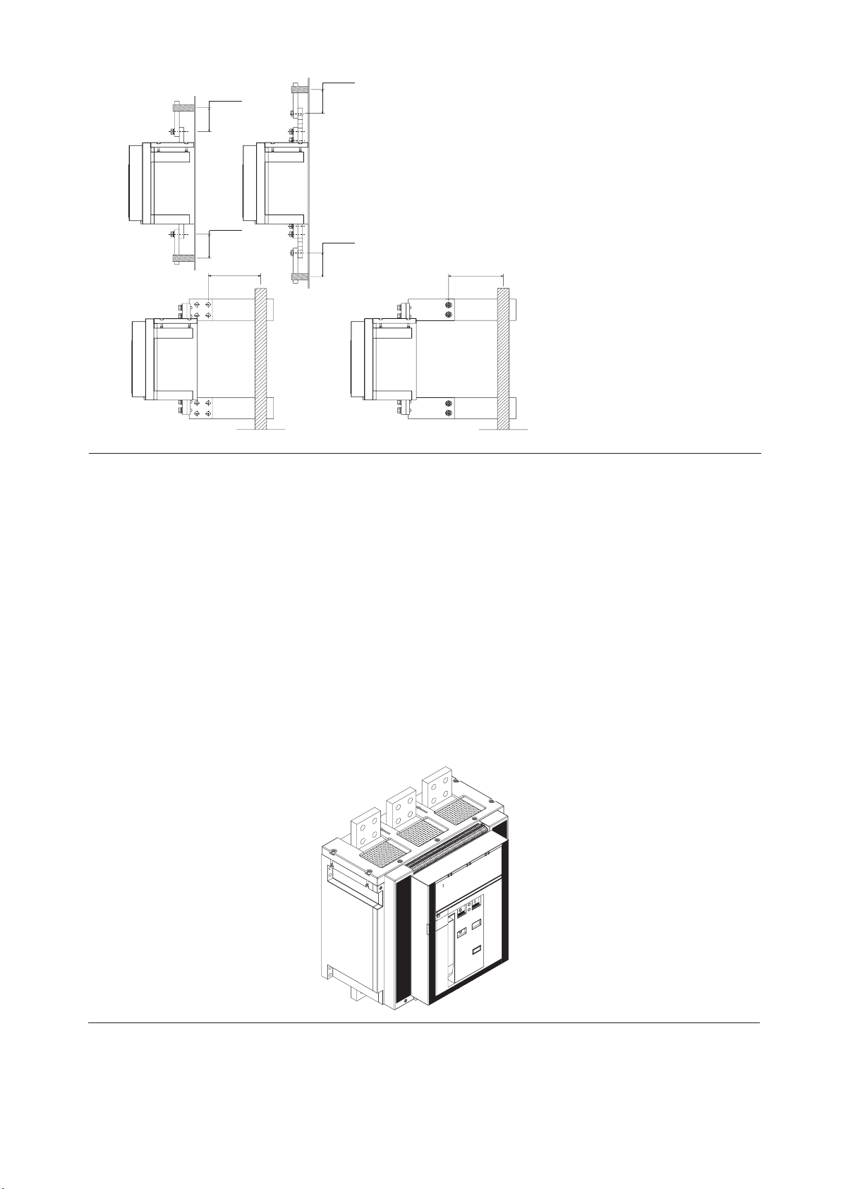
1.2 External front view of the circuit-breaker
1
2
Fig. 1
1 LSIG electronic microprocessor-based release
2 Operating and control parts of the operating mechanism and release-tripped signals
3 Rating plate
3
2. Checking on receipt
Examine the condition of the material received and make sure that it corresponds to what was ordered. Any damage or non-compliance found
when the material has been unpacked, which must be carried out with due care, must be notified within 5 days of receipt and the number of the
shipping notice must be indicated on the notification.
3. Storage, lifting and weights
Protected by an external wooden crate, the circuit-breaker is fastened with screws to the pallet used for transport or to the bottom of the packing crate.
If the circuit-breaker must be stored for even a short period of time before being put into service, after having been checked on receipt it must
be its back into its container and covered with a waterproof tarpaulin.
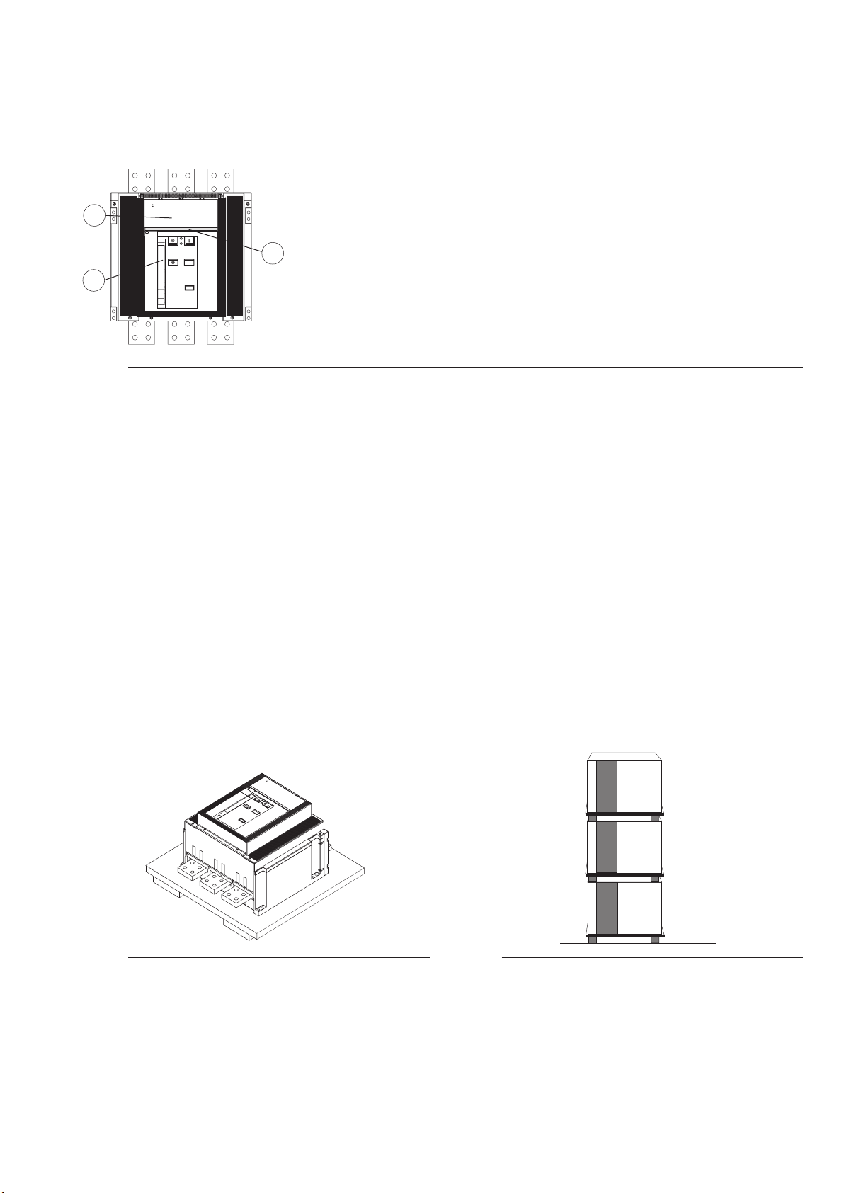
Caution
– Store the circuit-breaker in a dry, dust-free room well away from aggressive chemicals.
– Place the circuit-breaker and any fixed part on a horizontal surface, not in direct contact with the floor but on a suitable support (Fig. 4).
– The maximum number of circuit-breakers that can be stacked on top of each other is shown in figure 5.
– Keep the circuit-breaker in the open position with the closing springs unloaded to prevent unwarranted stress and the risk of accidents to the
personnel.
Fig. 4
DIR 1000682R0002 (L5757)
Fig. 5
(3)
Page 4
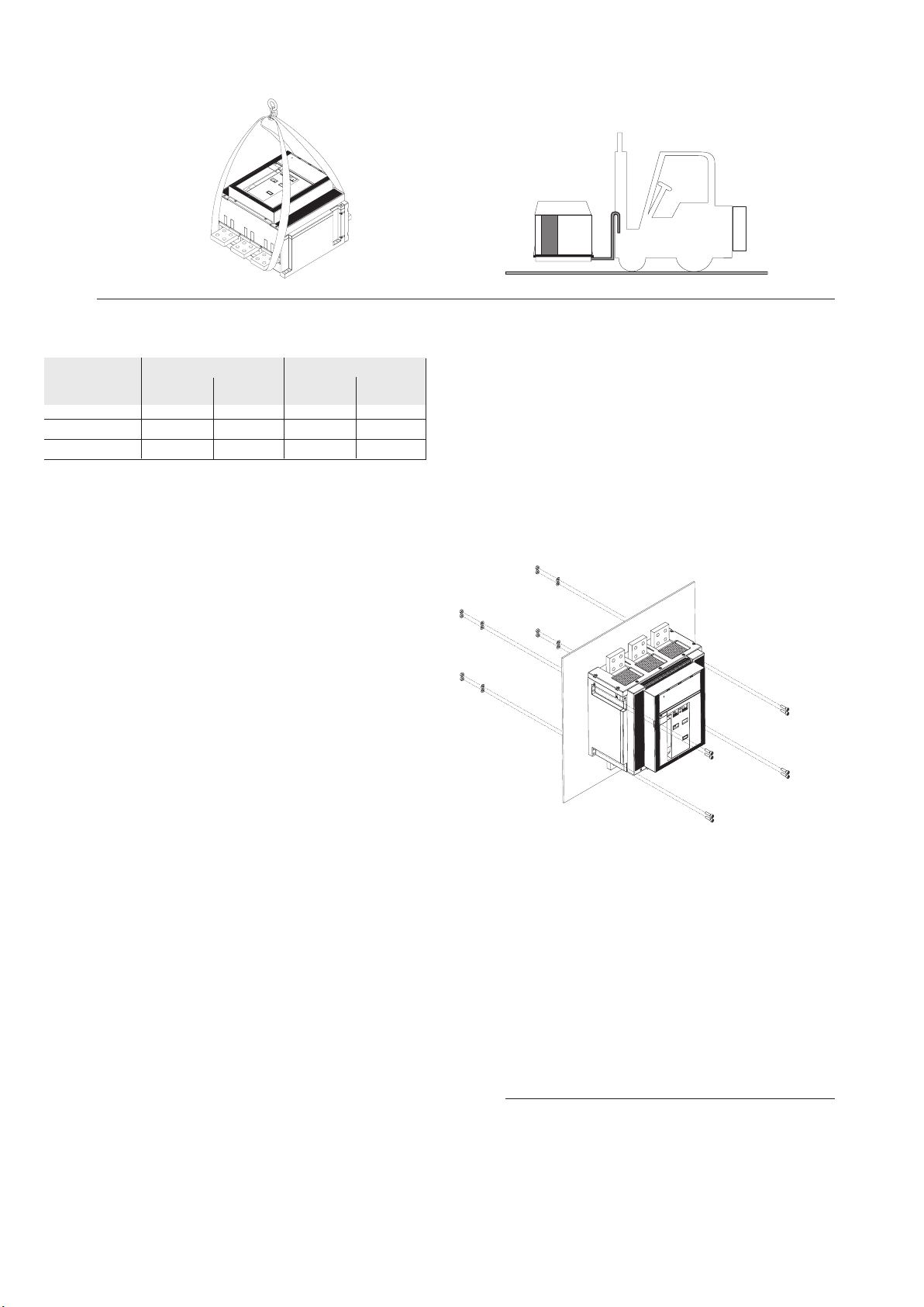
Comply with the following instructions when lifting the circuit-breaker: the circuit-breakers must be placed on a sturdy surface and preferably lifted
with an appropriate fork-lift truck. The use of ropes is, however, permitted: In this case, the lifting ropes ust be attached as shown in the figure.
Fig. 6
Table of circuit-breaker weights (kg)
Circuit-breaker 3 poles 4 poles
kg lbs kg lbs
T8 2000 73 161 95 209
T8 2500 73 161 95 209
T8 3000 95 209 125 276
Note
The weights given in the table refer to circuit-breakers complete with LSIG releases and relative current sensors, excluding the accessories.
4. Installation
4.1 Installation conditions
Install the circuit-breaker in a dry, dust-free, non-corrosive place where it
will not be subjected to shocks or vibrations. When this is not possible,
assemble it inside a switchboard with a suitable degree of protection.
For preparation of the installation ambient, refer to the “Overall dimensions” chapter, which provides information about the following points:
– minimum installation volumes of the circuit-breakers and derived
versions
– clearances to be respected for circuit-breakers in compartments
– overall dimensions of the circuit-breakers
– drilling holes for fixing purposes
– drilling holes in the compartment door
The operations required for installation, putting into service, routine and
supplementary maintenance must be performed by skilled personnel
with detailed knowledge of the equipment.
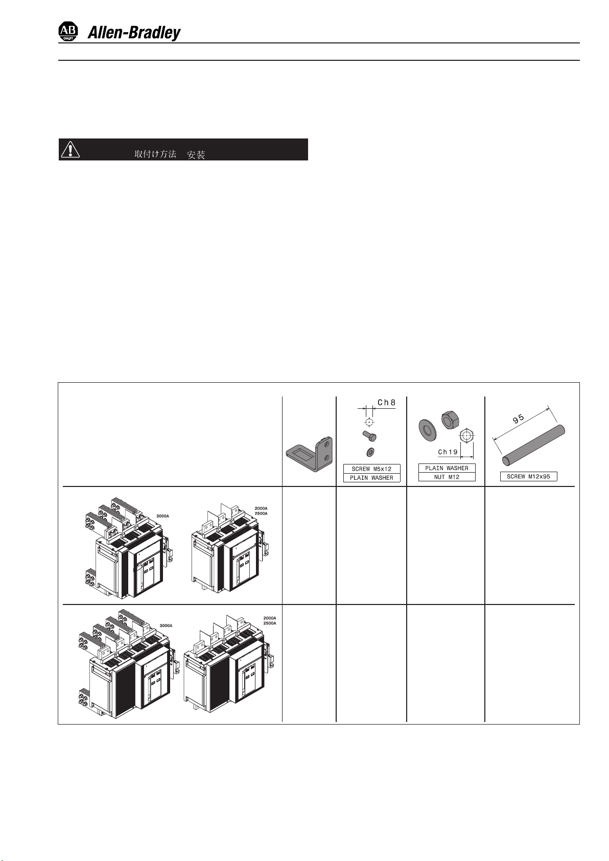
To install a circuit-breaker in the switchboard, just fix it to a vertical
surface with M8 screws. (fig. 7 )
The circuit-breaker must only be installed in a vertical position.
DIR 1000682R0002 (L5757)
Fig.7
(4)
Page 5
4.2 Installation of the flange on the compartment door (Fig. 8)
– Drill the holes in the compartment door indicated in the section entitled “Overall dimensions”.
– Apply the flange (1) to the front of the compartment door and fix it from the inside with the self-tapping screws (2).
2
1
Fig. 8
5. Electrical connections
5.1 Power circuit connections
Use insulated bars/ perform specific type tests on the installation.
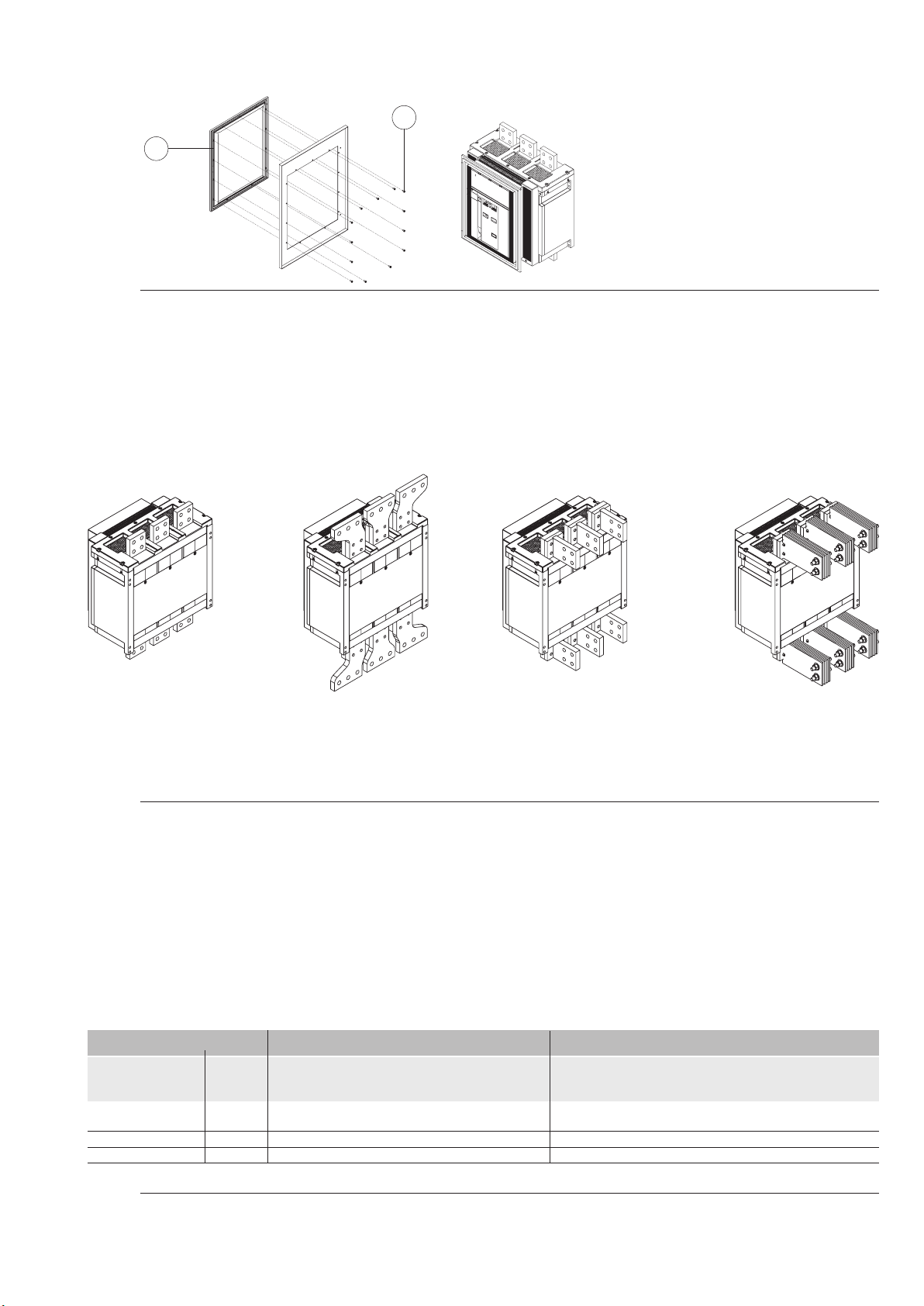
5.1.1 Shapes of the terminals
F ES
Front terminals
Fig. 9
Note
The drawings provide a schematic illustration of the type of terminal. The exact shape of the terminals is given in the chapter entitled “Overall
dimensions". The terminals installed on the upper and lower parts (input and output) can be different from each other.
Extended front
terminals
(IEC)
nals for flat bar ( VR for
VR
Adjustable rear termi-
IEC/UL; HR for IEC)
VR
Vertical rear
terminals
5.1.2. Examples of connection busbar layouts depending on the types of terminals
The busbars allow connections to be made between the terminals of the circuit-breaker and the busbars of the switchboard. They must be accurately sized by the switchboard design engineer.
This section illustrates examples of possible constructions, depending on the shape and size of the circuit-breaker terminals.
It is normally advisable to use the entire contact surface of the terminal, thus the width of the busbar should be the same as that of the terminal.
Different capacities can be obtained for the connections by adjusting the thickness and number of busbars in parallel. In certain cases, reductions
in the width of the connection in relation to that of the terminal can be allowed, as shown in the examples below.
Front terminals Vertical rear terminals
Circuit-breaker Iu [A] Busbar cross-section Busbar cross-section
[mm2]/[in2] [mm2]/[in2]
140G-R 2000 3x(100x5) / 3x(3.94x0.2) 3x(100x5) / 3x(3.94x0.2)
140G-R 2500 4x(100x5) / 4x(3.94x0.2) 4x(100x5) / 4x(3.94x0.2)
140G-R 3000 - 5x(102x6.4) / 5x(4x0.25)
Fig. 10
DIR 1000682R0002 (L5757)
(5)
Page 6
Positioning the rst anchor plate of the busbars
Anchoring to the switchboard
190
7.48"
190
7.48"
190
7.48"
190 190
7.48"
Fig. 11
190
7.48"
7.48"
5.2.3 Assembly procedures for the connection busbars
Check the state of the contact surfaces of the connections very carefully: they must be very clean and free from burrs, dents and traces of rust
- which must be removed with a fine file or emery cloth to prevent localized increases in temperature. On completion of the operation, remove
any traces of grease or dust with a cloth soaked in a suitable solvent.
When aluminium connections are used, the contact surfaces must be tin-plated.
Make sure that the connections are unable to exert any strain on the terminals in any direction.
Always insert a flat washer with a large diameter (to distribute the tightening pressure over the widest possible area) and a spring washer.
Establish contact between the connection and terminal and fully tighten the fixing screws.
Always use two wrenches (to prevent the insulating parts from being unduly stressed) and apply the tightening torque of the main terminals = 70
Nm/615 lb in for M12 high-strength screws. Check tightness after 24 hours.
5.2 Wiring of the auxiliary circuits of the circuit-breaker
There is a special terminal board fitted with screw terminals for connecting the auxiliary circuits.
The terminals are marked with alphanumerical identification codes as indicated in the electrical circuit diagram.
The terminal board is accessed immediately when the compartment door is opened.
Fig. 12
DIR 1000682R0002 (L5757)
(6)
Page 7

6. Putting into service
6.1 General procedures
– Make sure that the power connections to the circuit-breaker terminals are tight
– Perform al the preparatory operations on the release
– Make sure that the power supply voltage of the auxiliary circuits is between 85% and 110% of the rated voltage of the electrical applications
– To avoid temperature rises, make sure that there is sufficient air exchange in the installation area
– Also perform the inspections indicated in the following table.
Item inspected
1 Manual operating mechanism
2 Gearmotor (if provided)
3 Undervoltage release
(if provided)
4 Shunt closing release (if provided)
5 Shunt opening release (if provided).
6 Lock for circuit-breaker in open position
(key or padlock)
7 Auxiliary circuit-breaker contacts
Procedure
Perform a few opening, closing and release
operations (see chap. 7.2).
WARNING
When there is an undervoltage release, the circuit-breaker can only be closed after the release
itself has been electrically energized.
Supply the spring loading gearmotor at the
relative rated voltage.
Perform a few closing and opening operations.
Note. Supply the undervoltage release at the
relative rated voltage (if provided).
Supply the undervoltage release at the relative
rated voltage and perform the circuit-breaker
closing operation.
Turn off the voltage supply to the release.
Supply the undervoltage release at the relative
rated voltage and perform the circuit-breaker
closing operation.
Close the circuit-breaker.
Supply the shunt opening release at the relative
rated voltage.
Open the circuit-breaker.
Power the shunt closing release at the its
rated voltage.
Open the circuit-breaker, turn the key and
remove it. Attempt the circuit-breaker closing
operation.
Insert the auxiliary contacts into appropriate
signalling circuits. Perform a few circuit-breaker
closing and opening operations.
Successful check
The spring loading lever moves normally.
The springs are loaded normally.
The signals are normal.
The gearmotor stops when the springs have
been loaded.
The gearmotor reloads the springs after each
closing operation.
The circuit-breaker closes normally. The signals
are normal.
The circuit-breaker opens. The signal changes
over.
The circuit-breaker opens normally. The signals
are normal.
The circuit-breaker closes normally. The signals
are normal.
Both manual and electrical closing are prevented.
Signalling occurs normally.
DIR 1000682R0002 (L5757)
(7)
Page 8
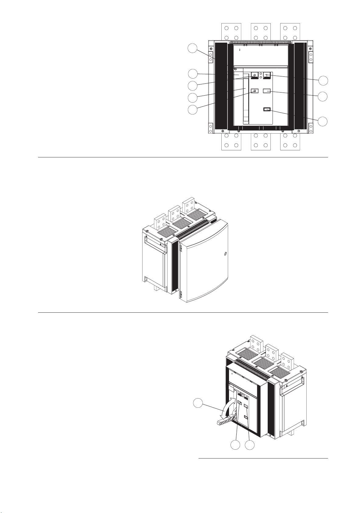
7. Instructions for use
7.1 Operating and signalling components
1 Push-button for the manual opening operation
2 Lever for manual loading of the closing springs
3 Mechanical indicator for circuit-breaker open “O” and closed “I”
4 Mechanical indicator for protection release tripped
5 Pushbutton for the manual closing operation
6 Indicator for springs loaded - unloaded
7 Operation counter (to order)
8 Key lock on the closing operation (to order)
Fig.13
Note
On request, a transparent cover that increases the degree of protection to IP54 can be installed on the front of the circuit-breaker. The cover is
equipped with a key lock.
4
8
1
2
3
5
6
7
Fig. 14
7.2 Circuit-breaker closing and opening procedures
Circuit-breaker operation can be either manual or electrical.
a) Manual operation for loading the closing springs
– Make sure that “O” (circuit-breaker open) is displayed by the indicator
– Make sure that the indicator (6) is WHITE (springs unloaded)
– Repeatedly operate the lever (2) until the colour of the indicator (6)
changes to YELLOW
b) Electrical operation for loading the closing springs
Electrica operation of the circuit-breaker is possible when the following
accessories are present (supplied to order):
– gearmotor for automatic loading of the closing springs
– shunt closing release
– shunt opening release.
The gearmotor automatically reloads the springs after each closing
operation until the yellow indicator appears (6, Fig. 15). If there is a
power failure during the loading operation, the gearmotor stops and
automatically continues with the spring loading operation once the
power returns. However, it is always possible to complete the reloading
operation in the manual mode.
Fig. 15
2
3
6
DIR 1000682R0002 (L5757)
(8)
Page 9
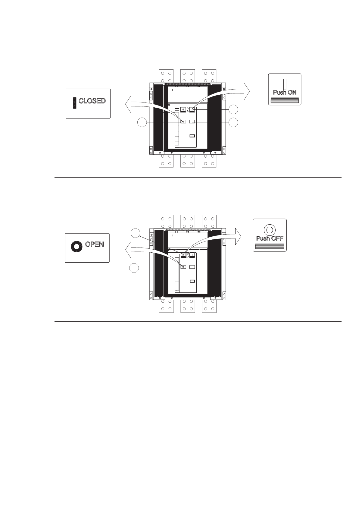
c) Circuit-breaker closing
This operation can only be carried out when the closing springs are fully loaded.
Press the push-button (5) marked with the letter “I” for closing in the manual mode. When there is a shunt closing release, the operation can also
be carried out in the remote mode by means of the special control circuit. Closing is signalled by the relative indicator (3), which moves to the
“I” position. Moreover, the indicator of the state of the springs (6) moves to the WHITE position. The control has enough energy for the opening
operation even when the closing springs are unloaded. If present, the gearmotor immediately begins the automatic spring loading operation.
5
3
Fig. 16
d) Circuit-breaker opening
Press the push-button “O” (1) to open the circuit-breaker in the manual mode. When there is a shunt opening release, the operation can also
be carried out in the remote mode by means of the special control circuit. The open state is signalled by the appearance of the letter “O” in the
indicator (3).
1
3
6
Press
Press
Fig. 17
DIR 1000682R0002 (L5757)
(9)
Page 10

8. Maintenance
8.1. Warnings
WARNING: before proceeding with any maintenance operation, it is obligatory to:
- Oen the circuit-breaker and make sure that the springs of the operating mechanism are unloaded;
- if work must be performed on xed circuit-breakers or on xed parts, disconnect the power supply to the power
circuit and auxiliary circuits and visibly earth the terminals on both the supply side and load side;
- Set the equipment to safe conditions as established by the standards and laws in force.
WARNING RISK OF ELECTRIC SHOCK: Risk of electric shock or accident.
AB declines all liability for damage to persons or property caused by failure to comply with the instructions in this document.
The maintenance operations must be performed by skilled personnel with detailed knowledge of the equipment.
8.2. Maintenance program
8.2.1. Circuit-breaker life
When regular maintenance is performed, 140G-R circuit-breakers - with or without shunt opening or shunt closing devices - can
withstand the following operating cycles without replacement of parts.
Rated uninterrupted
current
Iu (40 °C)
[A]
Mechanical life
N° of
operations
x 1000
T8
T8
T8
(1)
These data refer to the standard installation in accordance with the product standards.
(2)
Extreme weather conditions, polluted atmosphere or vibrations can reduce the life of the application.
2000 15 60 4,5 30
2500 15 60 4 30
3000 15 60 3 30
(2)
Frequency
operations/
hour
(1)
Electrical life
415 V ~
N° of operations x 1000
(2)
Frequency
operations/hour
8.2.2. Maintenance program
We hereby include the table indicating the frequency with which maintenance should be carried out and the relative routine
maintenance operations required.
Compliance with the following rules is also recommended:
- Even circuit-breakers that are operated infrequently or that remain closed or open for long periods of time must be subjected
to programmed maintenance.
- Installation of the mechanical operation counter (supplied on request) is recommended for circuit-breakers equipped with LSIG
releases.
- During service, visually inspect the circuit-breaker from the outside to make sure there is no dust, dirt or damage of any kind.
Intervals
Maintenance operations
First Level
One year, or 20% of mechanical life, or 20%
Installations in normal places
of electrical life
Three years, or 50% of mechanical life, or
Second Level
50% of electrical life, or after a trip under
short-circuit
(1)
These data refer to the standard installation in accordance with the product standards.
(2)
Extreme weather conditions, polluted atmosphere or vibrations can reduce the life of the application.
Installations in dusty or polluted places
(1) = level of dust measured > 1 mg/m³ ]
6 months, or 10% of mechanical life, or 10%
of electrical life
18 months, or 25% of mechanical life, or
25% of electrical life, or after a trip under
short-circuit
( 1)/( 2)
[
8.3. First Level maintenance operations
DIR 1000682R0002 (L5757)
(10)
Page 11

8.3.1. Preliminary operations:
- open the circuit-breaker and make sure that the springs of the operating mechanism are unloaded.
WARNING: if work must be performed on the circuit-breakers, disconnect the power circuit and auxiliary circuits
and earth the terminals in a visible way on both the supply side and load side.
8.3.2. General inspections and cleaning:
- Check to make sure that the device is clean. Remove any dust and traces of oil or grease with a clean, dry cloth (use a mild
detergent if necessary - A cleaning product such as Henkel’s 273471 or equivalent can be used if there is a heavy coating of dirt).
- Make sure that the rating plates with the technical specifications of the apparatus are affixed.
- The rating plates must be cleaned with a clean, dry cloth.
- Remove all traces of dust, mould, condensation and tarnish
- Make sure that there are no foreign bodies in the circuit-breaker compartment.
8.3.3. Circuit-breaker connections and connections between circuit-breaker and switchboard
- Remove any dust and dirt with a brush and dry cloth - use a mild detergent if necessary. Use a cleaning product such as Henkel’s 273471 or equivalent if there is a heavy coating of dirt.
- Make sure that there are no traces of localized overheating on the terminals. This problem is denoted by the change in the colour
of the parts in contact. These parts are usually silvery in colour.
- Make sure that the bolts of the terminal connections are well tightened (M12 - 619.5 lb-in / 70 Nm).
WARNING: if work must be performed on the circuit-breakers, disconnect the power circuit and auxiliary circuits
and earth the terminals in a visible way on both the supply side and load side.
- Make sure that the cable connecting screws are well tightened in the terminal boxes (6.19 lb-in / 0.7 Nm).
Fig. 18
8.3.4. Flange and escutcheon plate disassembly operations
– Make sure that the circuit-breaker has been set to safe conditions as described in sect. 8.1
– Remove the flange (1) of the release as shown in figure 19.
– Remove the front escutcheon plate (2) by removing the four screws (3).
– Remove both the side guards (4) by removing the front screws (5).
4
5
1
3
3
2
T8 3p
5
1
2
Fig. 19
4
T8 4p
DIR 1000682R0002 (L5757)
(11)
Page 12

- If the undervoltage release is installed, disassemble the coil support and unload the springs of the operating mechanism by
1
closing and opening the circuit-breaker.
Fig. 20
8.3.5. Mechanical operating mechanism
- Clean the points indicated in figure 21. Use a cleaning product such as Henkel’s 273471 or equivalent if there is a heavy coating of dirt.
- Lubricate the opening and closing latches and the shafts in the points indicated in figure 21.
- Make sure that the opening and closing shafts are free to turn.
Fig. 21
8.3.6. Electrical and mechanical accessories
- Make sure that the accessories are securely fixed to the circuit-breaker.
- Make sure that the electrical accessories are correctly connected to the circuit-breaker.
- Gearmotor: after every 10000 operations, check the brushes for wear and replace the gearmotor if necessary.
- Make sure that the releases (opening/undervoltage/closing) are in good conditions (absence of excessive wear, overheating,
breakages) Fig. 22.
Make sure that the mechanical operation counter functions correctly (if applicable) by operating the circuit-breaker.
WARNING: warning lever has to be activated only in case of coils set substitution. Do not operate it in other
conditions
Warning
lever
2
1
17.7 lb-in
2 Nm
Fig. 22
DIR 1000682R0002 (L5757)
(12)
Page 13

8.3.7. Protection releases
- -Power the protection release with a battery unit.
- Make sure that the protection release functions correctly: release test with the “Trip Test”.
- Make sure that the front leds do not indicate the presence of alarms.
- Make sure that the cables are correctly connected to the release modules and to the release itself (if applicable).
- Remove the battery unit from the relay upon termination.
8.3.8. Maintenance operations; nal inspections
- Fit all the parts back in place and re-connect the auxiliary power supply if necessary.
- Re-assemble the escutcheon plate as shown in figure 23.
- Using the different auxiliaries in succession, perform the operations 10 times:
- Opening (in both the local and remote modes, if applicable)
- Closing (in both the local and remote modes, if applicable)
- Release by means of the trip test via relay
- Check the operations in accordance with the following sequence:
- Open - Springs unloaded
- Open - Springs loaded
- Closed - Springs unloaded
- Closed - Springs loaded
- Make sure that the accessories (if installed) function correctly
- Make sure that the gearmotor (if installed) functions correctly
- Make sure that the undervoltage release functions correctly (if installed)
- Make sure that the shunt opening release functions correctly (if installed)
- Make sure that the shunt closing release functions correctly (if installed)
- Make sure that the circuit-breaker's auxiliary contacts function correctly (if installed)
- Make sure that the lock for circuit-breaker in open position (key or padlock) functions correctly (if installed)
DIR 1000682R0002 (L5757)
(13)
Page 14

8.4. Second Level maintenance operations
8.4.1. Preliminary operations:
- open the circuit-breaker and make sure that the springs of the operating mechanism are discharged.
WARNING: if work must be performed on the circuit-breakers, disconnect the power circuit and auxiliary circuits
and earth the terminals in a visible way on both the supply side and load side.
8.4.2. General inspections and cleaning:
- Check to make sure that the device (interrupting part) is clean. Remove any dust and traces of oil or grease with a clean, dry
cloth (use a mild detergent if necessary - A cleaning product such as Henkel’s 273471 or equivalent can be used if there is a
heavy coating of dirt).
- Make sure that the rating plates with the technical specifications of the apparatus are affixed
- The data plates can be cleaned with a clean, dry cloth.
- Remove all traces of dust, mould, condensation and tarnish
- Make sure that there are no traces of overheating or cracks, which could impair the isolating parts of the circuit-breaker
- Make sure that there are no foreign bodies in the circuit-breaker compartment
- Make sure that the screws that fasten the fixed part to the switchboard are well tightened (M8 - 221.3 lb-in / 25 Nm).
8.4.3. Circuit-breaker connections and connections between circuit-breaker and switchboard
- Remove any dust and dirt from the isolating parts with a brush and dry cloth (use a mild cleaning product if necessary - A
cleaning products such as Henkel’s 273471 or equivalent can be used if there is a heavy coating of dirt).
- Make sure that there are no traces of localized overheating on the terminals. This problem is denoted by the change in the
colour of the parts in contact. These parts are usually silvery in colour.
- Make sure that the bolts of the terminal connections are well tightened (M12 - 619.5 lb-in / 70 Nm).
WARNING:
if work must be performed on the circuit-breakers, disconnect the power circuit and auxiliary circuits and earth
the terminals in a visible way on both the supply side and load side.
- Make sure that the cable connecting screws are well tightened in the terminal boxes (6.19 lb-in / 0.7 Nm).
Fig. 24
8.4.4. Flange and escutcheon plate disassembly operations
– Make sure that the circuit-breaker has been set to safe conditions as described in sect. 8.1
– Remove the flange (1) of the release as shown in figure 25.
– Remove the front escutcheon plate (2) by removing the four screws (3).
– Remove both the side guards (4) by removing the front screws (5).
4
5
1
1
3
4
5
2
Fig. 25
DIR 1000682R0002 (L5757)
T8 3p
(14)
3
2
T8 4p
Page 15

- If the undervoltage release is installed, disassemble the coil support and unload the springs of the operating mechanism by
det.A
det.B
closing and opening the circuit-breaker.
Fig. 26
8.4.5. Mechanical operating mechanism
- Clean (use a cleaning product such as Henkel’s 273471 or equivalent if there is a heavy coating of dirt) and lubricate (in the
points indicated in figure 27, det. A, as per the First Level) the shafts and opening closing latches.
- Clean (use a cleaning product such as Henkel’s 273471 or equivalent if there is a heavy coating of dirt) and lubricate the operating shaft supports, including those on the sides of the circuit-breaker (see figure 27, det. B).
- Make sure that the opening and closing shafts are free to turn.
Fig. 27
- Contact AB if the springs are deformed or tarnished, if rings are missing or if the control is excessively worn.
DIR 1000682R0002 (L5757)
(15)
Page 16

8.4.6. Electrical and mechanical accessories
17.7 lb-in
2
Warning
lever
1
1
9.7 lb-in
- Make sure that the accessories are securely fixed to the circuit-breaker.
- Make sure that the electrical accessories are correctly connected to the circuit-breaker.
- Gearmotor: after every 10000 operations, check the brushes for wear and replace the gearmotor if necessary.
- Make sure that the releases (opening/undervoltage/closing) are in good conditions (absence of excessive wear, overheating,
breakages) Fig. 28.
- Make sure that the mechanical operation counter functions correctly (if applicable) by operating the circuit-breaker.
WARNING: warning lever has to be activated only in case of coils set substitution. Do not operate it in other
conditions
Fig. 28
8.4.7. Protection releases
- -Power the protection release with a battery unit.
- Make sure that the protection release functions correctly: release test with the “Trip Test”.
- Make sure that the front leds do not indicate the presence of alarms.
- Make sure that the cables are correctly connected to the release modules and to the release itself (if applicable).
- Remove the battery unit from the relay upon termination.
8.4.8. Maintenance operations; nal inspections
- Fit all the parts back in place and re-connect the auxiliary power supply if necessary.
- Re-assemble the escutcheon plate as shown in figure 30.
Fig. 29
- Using the different auxiliaries in succession, perform the operations 10 times:
- Opening (in both the local and remote modes, if applicable)
- Closing (in both the local and remote modes, if applicable)
- Release by means of the trip test via relay
- Check the operations in accordance with the following sequence:
- Open - Springs unloaded
- Open - Springs loaded
- Closed - Springs unloaded
- Closed - Springs loaded
- Make sure that the accessories (if installed) function correctly
- Make sure that the gearmotor (if installed) functions correctly
- Make sure that the undervoltage release functions correctly (if installed)
- Make sure that the shunt opening release functions correctly (if installed)
- Make sure that the shunt closing release functions correctly (if installed)
- Make sure that the circuit-breaker's auxiliary contacts function correctly (if installed)
- Make sure that the lock for circuit-breaker in open position (key or padlock) functions correctly (if installed)
DIR 1000682R0002 (L5757)
(16)
Page 17

9. Measures to be taken if operating faults occur
The circuit-breaker fails to open when the opening pushbutton is pressed
The circuit-breaker fails to open because opening coil has tripped
The circuit-breaker fails to open because undervoltage release undervoltage has tripped
The circuit-breaker fails to open when the protection relay release test is performed
The circuit-breaker fails to close when the closing pushbutton is pressed
The circuit-breaker fails to close because closing coil has tripped
The closing springs cannot be loaded with the manual loading lever
The closing springs cannot be loaded with the spring-loading motor
The circuit-breaker cannot be locked in the open position
Possible causes
•
• • •
The opening solenoid of the relay is not
connected properly
Relay tripping signal not reset
Faults
Checks and solutions
Make sure that the opening solenoid is connected correctly
Press the mechanical pushbutton to reset the
relay tripping signal
• •
• •
•
• • •
• • •
• •
• •
• •
• •
• •
• • •
Supply votage of the auxiliary circuits too
low
Supply voltage different from the value indicated on the nameplate of these releases
Faulty switching circuit
Loose clamping screws of the wires and
auxiliary circuits
Incorrect electrical connections in the
power supply circuit
Coil damaged Replace the coil
Operating mechanism locked
Open position key lock activated Unlock by inserting the key
Undervoltage release not energized
Shunt opening release remains permanently energized
Operating mechanism locked Call Rocwell Automation
The fuse that protects the spring loading
•
motor protection has tripped
Faulty gearmotor for automatic spring
•
loading
Circuit-breaker closed
•
Lock in open position defective Call AB
•
Measure the voltage: it must not be less than
85% of the rated voltage of the coil
Check the voltage indicated on the nameplate of
the releases
Check the connections, fuses, interlocks, protection switches and accept contacts
Make sure that the wire clamping screws are
tight
Check the connections with the relative functional diagram
Operate in the manual mode. Contact AB if the
fault persists
Check the relative supply circuit and the supply
voltage
Check the supply circuit
Replace the fuse
Replace the gearmotor
Press the opening pushbutton and activate the
lock
WARNING: If the fault or failure of the circuit-breaker in your application could cause injuries, material damage
or is highly critical, the circuit-breaker itself must be immediately removed so that it can be inspected or repaired.
DIR 1000682R0002 (L5757)
(17)
Page 18

10. Accessories
10.1 Electrical accessories
Shunt opening / closing release (YO/YC)
Allows the device to be opened or closed by remote control. Given the characteristics of the circuit-breaker operating mechanism, opening (with
the circuit-breaker closed) is always possible, whereas closing is only possible when the closing springs are loaded. Most of the releases can
operate with both direct and alternate current.
This release provides an instantaneous service (*), but can be supplied permanently (**).
In uses where the shunt closing release is supplied permanently, the shunt closing release must be momentarily de-energized in order to reclose
the circuit-breaker after opening (the circuit-breaker operating mechanism is, in fact, fitted with an anti-pumping device).
(*) In the case of instantaneous service, the current impulse must last at least 100 ms.
(**) In the case of permanent power supply to the shunt opening release, wait for at least 30 ms before transmitting the control to the shunt closing release.
Reference figure in the electrical circuit diagrams: YO (4) - YC (2)
Power supply [Un] 24 V DC
30 V AC/DC
48 V AC/DC
60 V AC/DC
110-120 V AC/DC
120-127 V AC/DC
220-240 V AC/DC
240-250 V AC/DC
380-400 V AC
440 V AC
Operating limits
(Standard CEI EN 60947-2)
Inrush power consumption (Ps)
Inrush power time ~100 ms
Continuous power (Pc)
Opening time (YO) (max) 60 ms
Closing time (YC) (max) 80 ms
Insulation voltage 2500V 50 Hz (for 1 min.)
(YO) : 70…110% Un
(YC) : 85…110% Un
DC = 200 W
AC = 200 VA
DC = 5 W
AC = 5 VA
Undervoltage release (YU)
The undervoltage release opens the circuit-breaker when there is a sensible reduction or lack of the voltage that powers it. It can be used for
remote tripping (by means of normally closed pushbuttons), as a lock on closing or to control the voltage in primary or secondary circuits. The
release power supply is therefore branched on the supply side of the circuit-breaker or from an independent source. Circuit-breaker closing is
only allowed with the release powered (the closing lock is obtained mechanically). The release can operate with both direct and alternate current.
Power supply [Un] 24 V DC
30 V AC/DC
48 V AC/DC
60 V AC/DC
110-120 V AC/DC
120-127 V AC/DC
220-240 V AC/DC
240-250 V AC/DC
380-400 V AC
Operating limits: (YO-YO2): 70% ... 110% Un
Standard CEI EN 60947-2. (YC): 85% ... 110% Un
440 V AC
Circuit-breaker opening takes place with power supply voltage values of the release equivalent to 35 - 70% Un.
Circuit-breaker closing can take place with power supply voltage values of the release equivalent to 85 - 110% Un.
IT can be fitted with a signalling contact for undervoltage release energized (C. aux YU).
Reference figure in the electrical circuit diagrams: YU (6)
Inrush power consumption (Ps):
Continuous power (Pc):
Opening time (YU):
Insulation voltage
DIR 1000682R0002 (L5757)
DC = 200 W
AC = 200 VA
DC = 5 W
AC = 5 VA
30 ms
2500V 50 Hz (per 1 min.)
(18)
Page 19

Gearmotor for automatic loading of the closing springs (M)
Automatically loads the closing springs of the circuit-breaker's operating mechanism. Once the circuit-breaker has closed, the gearmotor immediately begins to reload the closing springs.
The closing springs can still be loaded in the manual mode (using the relative lever of the operating mechanism) in a power failure or during
maintenance work.
Power supply
100-130 V AC/DC
220-250 V AC/DC
Operating limits:
Insulation voltage: 2500 V 50 Hz (for 1 min.)
IT is always supplied with limit contacts and microswitch for signalling closing springs loaded.
Reference figure in the electrical circuit diagrams: M (1)
24-30 V AC/DC
48-60 V AC/DC
85…110% Un (Standard CEI EN 60947-2)
Inrush power consumption (Ps):
Rated power (Pn):
Inrush time 0.2 s
Loading time: 4-5 s
DC = 500 W
AC = 500 VA
DC = 200 W
AC = 200 VA
Mechanical and electrical trip signalling for overcurrent releases
The following signals are available after the overcurrent release has tripped:
a) Mechanical trip signalling for overcurrent releases
Enables visual signalling on the operating mechanism by pushing the trip button in when the circuit-breaker has been opened after the overcurrent
releases have tripped. The circuit-breaker can only be closed again by putting the pushbutton back in its normal p osition in the s tandard configurat ion.
Reference figure in the electrical circuit diagrams: S51 (13).
b) Electrical trip signalling for overcurrent releases
Enables visual signalling on the operating mechanism (mechanical) and remotely (electrically, by means of a change-over switch) of the circuitbreaker having opened after tripping of the overcurrent releases. The mechanical indicator pushbutton must be reset before the circuit-breaker
can be reset. Reference figure in the electrical circuit diagrams: S51 (13).
Auxiliary contacts
Auxiliary contacts installed on the circuit-breaker are available and allow an indication of the circuit-breaker's state to be obtained. A special version of the auxiliary contacts is also available (gold plated contacts) for use at less than 24 V rated voltage (digital signals).
Un In max T
125 V DC 0.3 A 10 ms
250 V DC 0.15 A 10 ms
The following versions are available:
a) Electrical signalling of circuit-breaker open/closed
ELECTRICAL signalling of the circuit-breaker state (open/closed) can be obtained with 4 auxiliary contacts.
The auxiliary circuits can have following configuration: 4 break/make contacts (4 change-over position contacts)
Reference figure in the electrical circuit diagrams: Q/1 to 4 (22)
b) Contact for signalling closing springs loaded/unloaded
This consists of a microswitch, which allows remote signalling of the state of the closing springs of the circuit-breaker operating mechanism.
The contact is always supplied with the spring loading gearmotor.
Reference figure in the electrical circuit diagrams: S33 M/2 (11)
Un In max cosϕ
250 V AC 5 A 0,3
400 V AC 2 A 0,3
Sensors for the neutral conductor outside the circuit-breaker
The sensor allows neutral protection to be achieved by means of connection to the overcurrent release and is only available for three-pole circuitbreakers. It is supplied on request.
Reference figure in the electrical circuit diagrams: UI/N
10.2 Mechanical locks
Lock in open position
The circuit-breaker can be locked in open position by means of a padlocks up to 3 padlocks (not supplied): Ø 4 mm.
Mechanical lock for compartment door
Supplied as standard, this device stops the compartment door from being operated when the circuit breaker is closed and prevents the circuit
breaker from being closed when compartment door is open.
IP54 door protection
This is provided by means of a transparent plastic escutcheon plate which fully protects the front of the circuit-breaker and allows the IP54 degree
of protection to be obtained. It is assembled on hinges and equipped with a key lock.
DIR 1000682R0002 (L5757)
(19)
Page 20

11. Protection releases - References
The 140G-R circuit-breaker can be accessorized with LSIG protection release.
Details about the operation of the relays are given in the following documents:
1000587R0001 Operating instructions for the protection releases of 140G-N, 140G-NS and 140G-R circuit-breakers
1000592R0001 LSIG Getting started
11.1 Safety notes
WARNING: this symbol highlights information about operations, actions or circumstances that can cause injuries to the personnel,
damage to the unit or economic losses.
Read this manual, the specific manuals of the electronic releases and the getting started manuals carefully and fully.
This device must only be used by qualified and expert personnel.
Ifb there are doubts about whether it can be used safely, the unit must be put out of service to prevent it from being used accidentally.
You must assume that the device is not safe to use if:
1. The unit shows visible signs of damage.
2. The unit does not function (e.g. with autotest or with the trip test unit).
3. The unit has been damaged during transport.
The circuit-breaker must be open before any servicing or replacements are made.
Also remember to disconnect any power supplies connected.
11.1.1. Notes for dielectric strength tests
it is forbidden to perform dielectric strength tests on the inputs and outputs of the releases.
11.2 General characteristics
The following table clearly illustrates the technical characteristics and the mix-and-matchability of the three relays.
Function/Unit LSIG
Current protections (L, S, I, G) S
Thermal memory S
Local bus for external accessory units S
PR030/B (Separate power supply unit) O
Key:
S : standard function/unit,
O : optional function/unit,
DIR 1000682R0002 (L5757)
(20)
Page 21

12. Overall dimensions
Version with front terminals 2000A (80% and 100% rated)/2500A (80% rated)
N
N
Key
1 Inside edge of compartment door
2 Drilled M8 holes for fixing circuit-
breaker (use M8 screws)
Fig. 31
DIR 1000682R0002 (L5757)
3 Insulating or insulated metal wall
5 No.2 holes for IP54 protection
6 Panle door internal plane reference
7 No.2 holes for door interlock (use
M5 screws)
(21)
Page 22

Version with extended front terminals 2000A/2500 - (Terminals not UL listed)
N
3
1
N
2
Note: For mechanical lock for compartment door dimensions refer to overall dimensions of 140G-R with
front terminals
2
Key
1 Inside edge of compartment door
2 Drilled M8 holes for fixing circuit-
breaker (use M8 screws)
3 Insulating or insulated metal wall
Fig. 32
DIR 1000682R0002 (L5757)
(22)
Page 23

Version with adjustable rear terminals in flat bar 2000A (80% and 100% rated)/2500A (80% rated)
N
3
1
N
2
Note: For mechanical lock for compartment door dimensions refer to overall dimensions of 140G-R with
front terminals
2
Key
1 Inside edge of compartment door
2 Drilled M8 holes for fixing circuit-
breaker (use M8 screws)
3 Insulating or insulated metal wall
Fig. 33
DIR 1000682R0002 (L5757)
(23)
Page 24

Version with vertical rear terminals 2500A (100% rated)/3000A (80% and 100% rated)
N
3
1
N
2
Note: For mechanical lock for compartment door dimensions refer to overall dimensions of 140G-R with
front terminals
2
Key
1 Inside edge of compartment door
2 Drilled M8 holes for fixing circuit-
breaker (use M8 screws)
3 Insulating or insulated metal wall
Fig. 35
DIR 1000682R0002 (L5757)
(24)
Page 25

Compartment dimensions Holes drilled in compartment door
Depth
3 POLES
4 POLES
Fig.36
Insulation distances for installation in metal cubicle
Fig.37
Fig.38
DIR 1000682R0002 (L5757)
(25)
Page 26

13. Circuit diagrams
WARNING:
Carefully read notes F and O on the circuit diagrams before installing the circuit-breaker.
OPERATING STATE SHOWN
The diagram illustrates the components in the following conditions:
- circuit-breaker open
- circuits de-energized
- releases not tripped
- motor operator with unloaded springs.
VERSIONS
Version without overcurrent release
The applications indicated in figures 13, 14, 41, 42, 43, 44, 45, 46, 62 cannot be provided with this version.
KEY
= Figure number of the diagram
* = See note indicated by the letter
A1 = Circuit-breaker appications
A4 = Example switchgear and connections for operation and signalling, outside the circuit-breaker
F1 = Delayed-trip fuse
K51 = LSIG electronic release with the following protection functions:
- L overload protection with inverse long-time delay trip setting I1
- S short-circuit protection with inverse or definite short time-delay trip setting I2
- I short-circuit protection with instantaneous time-delay trip-setting I3
- G earth fault protection with inverse short time-delay trip-setting I4
M = Motor for loading the closing springs
Q = Circuit-breaker
Q/1...5 = Auxiliary contacts of the circuit-breaker
S33M/1...3 = Limit contacts of the spring loading motor
S51 = Contact for electrical signalling of circuit-breaker open due to tripping of the overcurrent release.
The circuit-breaker can only be closed after the reset pushbutton has been pressed,or after the coil has been energized
S51/P1 = Programmable contact (signals overload in progress - start by default)
SC = Pushbutton or contact for closing the circuit-breaker
SO = Pushbutton or contact for opening the circuit-breaker
SO2 = Pushbutton or contact for opening the circuit-breaker with instantaneous trip
TI/L1 = Current transformer located on phase L1
TI/L2 = Current transformer located on phase L2
TI/L3 = Current transformer located on phase L3
TU = Isolation voltage transformer (see note O)
Uaux. = Auxiliary power supply voltage (see note F)
UI/L1 = Current transformer (Rogowski coil) located on phase L1
UI/L2 = Current transformer (Rogowski coil) located on phase L2
UI/L3 = Current transformer (Rogowski coil) located on phase L3
UI/N = Current transformer (Rogowski coil) located on neutral
W2 = Serial interface with the accessories of releases LSIG (internal bus)
X1...X7 = Connectors for the circuit-breaker appications
XK1 = Connector for the power circuits of releases LSIG.
XO = Connector for YO1 release
XR3…XR13 = Connectors for the auxiliary circuits of releases LSIG.
XV = Delivery terminal box for the auxiliary circuits of the circuit-breaker
YC = Shunt closing release
YO = Shunt opening release
YO1 = Overcurrent shunt opening release (trip coil)
YU = Undervoltage release (see notes B and Q)
for electrical reset (if available)
DESCRIPTION OF FIGURES
Fig.1 = Circuit of the motor for loading the closing springs.
Fig.2 = Circuit of shunt closing release.
Fig.4 = Shunt opening release.
Fig.6 = Instantaneous undervoltage release (see notes B and Q).
Fig.11 = Contact for electrical signalling of springs loaded.
Fig.13 = Contact for electrical signalling of circuit-breaker open due to tripping of the overcurrent release.
The circuit-breaker can only be closed after the reset pushbutton has been pressed, or after the coil has
been energized for electrical reset (if available)
Fig.22 = Auxiliary contacts of the circuit-breaker
Fig.41 = Auxiliary circuits of the LSIG release (see note F).
NOTES
B) The undervoltage release is supplied for operation using a power supply branched on the supply side of the circuit-breaker or from an
independent source: the circuit-breaker can only close when the release is energized (there is a mechanical lock on closing).
If there is the same power supply for the closing and undervoltage releases and the circuit-breaker must close automatically when the
auxiliary voltage returns, a 30 ms delay must be introduced between the accept instant of the undervoltage release and energizing of
the closing release. This can be achieved by means of a circuit outside the circuit-breaker comprising a permanent closing contact, the
contact indicated in fig. 12 and a time-delay relay.
F) The auxiliary voltage Vaux allows all the functions of LSIG releases to be activated.
Since a Vaux isolated from earth is required, it is necessary to use “galvanically separated converters” conforming to standards
DIR 1000682R0002 (L5757)
(26)
Page 27

IEC 60950 (UL 1950) or equivalent, able to guarantee a common mode current or leakage current (see IEC 478/1, CEI 22/3) of no more
than 3.5mA, IEC 60364-41 and CEI 64-8.
U) The shield of the connection cable must be earthed on the circuit-breaker side only. The connection must be made with shielded two-wire
cable (the BELDEN 3105A type) no more than 15 meters in length.
Z) Short-circuit T5 and T6 if the outside neutral current sensor (UI/N) is not connected.
Circuit diagram symbols (Standards IEC 60617 and CEI 3-14...3-26)
Shield (may be drawn in any
shape)
Time delay
Mechanical or electrical
connection
Manual mechanical control
(general case)
Rotating control
Pushbutton control
Equipotentiality
Terminal or clamp
Socket and plug
(female and male)
Motor
(general symbol)
Current transformer
Voltage transformer
Winding of three-phase
transformer, star connection
Make contact
Change-over position contact with momentary circuit
breaking (limit contact)
Power isolator with automatic opening action
Switch-disconnector
Control coil
(general symbol)
Instantaneous
overcurrent relay
Overcurrent relay
with adjustable short
time-delay trip
Overcurrent relay with
inverse short time-delay
trip
DIR 1000682R0002 (L5757)
Galvanically separated
converter
Shielded cable conductors
(e.g. three conductors)
Conductors or stranded
cables (e.g. 3 conductors)
Conductor connections
Break contact with
automatic breaking
Change-over contact
Make position contact
(limit contact)
Break position contact
(limit contact)
(27)
Overcurrent relay
with inverse long time-delay
trip
Overcurrent relay
for earth fault with inverse
short
time-delay
Fuse
(general symbol)
Current sensor
Page 28

Circuit diagram - Operating state
Three-pole circuit-breaker with LSIG electronic release
Four-pole circuit-breaker with LSIG electronic release
Z
U
Motor operator, opening, closing and undervoltage releases
U
DIR 1000682R0002 (L5757)
(28)
Page 29

Allen-Bradley, Rockwell Software, and Rockwell Automation are trademarks of Rockwell Automation, Inc.
Copyright © 2013 Rockwell Automation, Inc. All Rights Reserved.
Signalling contacts
(B)(A)
W2
Q/5
XR11
64
XR1113
63
61
2 XR11
K21
K21
S51/P1
ACHTUNG: Anmerkung F
ATENCIÓN: leer la nota F
WARNING: read note F
ATTENTION: lire remarque F
ATTENZIONE: vedere nota F
N)
*
K14
K11
K15
K14
K15
SZin(DFin)
SZout(DFout)
K11
K51K51
GZout(DBout)
GZin(DBin)
K51
K13
K13
K51
K12
K12
W4
W4W3
W3
-
+
*
F)
24V
K2
K2
K1
K1
K51
Uaux.
PR332/P
7XR38XR3
XR3 19XR3 20 XR3 9
98P
98P
10XR3
95P
95P
XR3 17 XR3 18
16XR315XR314XR313XR3
Auxiliary circuits of releases LSIG
F)
*
-
+
A4
XV
A1
K51
XV
K1
K1
20XR3 19XR3 9XR3
XR3 8 XR3 7 XR3 10
W3
W3 W4
Uaux.
24V
K2
W4
WARNING: read noteF
ATTENZIONE: vedere notaF
ACHTUNG: Anmerkung F
ATTENTION:lire remarque F
ATENCIÓN: leer la notaF
K2
S51/P1
41
98P
98P
PR331/P
95P
95P
A4
(A) (B)
W2
Trademarks not belonging to Rockwell Automation are property of their respective companies.
Pubblication 140G-IN074A-MU-P - April 2013
DIR 1000682R002 (L5757) - L8271
 Loading...