

Rockford Fosgate POWER 650 MOSFET Owner's Manual

POWER
650
MOSFET
POWER
AMPLIFIER

INDEX
INTRODUCTION
........................................
1
Amplifier Features
.......................................
2
MOSFET Power Amplifiers
...............................
2
System Flexibility
........................................
3
Amplifier Bridging
.......................................
3
Speaker Impedance
.....................................
4
Amplifier Block Diagram
.................................
5
Why Biamplify? .........................................
6
Speaker Power Ratings
..................................
7
Speaker Fusing
..........................................
8
Internal Fusing.. ........................................
8
Crossover System
.......................................
9
Using the Crossovers
....................................
9
Typical Crossover Settings
..............................
10
Speaker Phasing
.......................................
10
Crossover Response Curves
............................
11
Amplifier Power Wiring
..................................
12
Din Interconnect Cable
.................................
13
Input Mode Switch
.....................................
13
Battery and Charging System
...........................
14
Passive Crossovers
.....................................
14
6 dB/Octave Crossovers
................................
16
12 dB/Octave Crossovers
...............................
17
18 dB/Octave Crossovers
...............................
18
Turn on Connection
....................................
19
Amplifier Mounting
.....................................
19
Power 650 MOSFET Specifications
......................
20
Biamplified Stereo Mode Wiring Diagram
................
22
Biamplified Stereo Diagram
.............................
23
Biamplified Stereo Bridged Mono Woofer Diagram
.......
24
Dual Stereo Diagram
...................................
25
Bridged Stereo Diagram
................................
26
Bridged Mono Biamplified Diagram
...................... 27

INTRODUCTION
The Power 650 MOSFET is a high-performance four-channel
power amplifier for cars, vans, or wherever a 12-volt battery is
available. It is designed to be used with a Rockford-Fosgate
equalizer/pre-amplifier and/or any high-quality radio, tape
player, compact disc player, or other music source.
Power amplifiers with rugged, fast MOSFET design and forced-
air cooling system combined produceeffortless performance at
over 650 Watts total output power. Switch-controlled crossovers
and easily-bridgeable, load-tolerant amplifiers make biamplified
systems, bridged systems, four-channel systems, and combinations easy to design.
Protection circuitry in the amplifier prevents damage due to
load shorts, system power problems, and internal failures. The
amplifier incorporates internal battery line filtering and extensive noise prevention circuitry.
The Power 650 MOSFET is designed to be professionally
installed. The length and nature of your warranty are dramat-
ically affected if you attempt to install it yourself (see Warranty).
Skill and experience are required to achieve high-end sound,
reliability, and appearance in a high-powered autosound
system. If you want to install your own unit, read this booklet
completely, research speaker systems and source units
extensively
-
and good luck!

POWER 650 MOSFET FEATURES
The Power 650 MOSFET amplifier combines a number of
capabilities that make it the highest-performance amplifier on
the road.
l 650 Watts total power (stereo mode, 4-Ohm loads)
l 4-, 3-, or 2-channel operation, biamplified or stereo
l Rugged and fast MOSFET design
l 30-Ampere peak current capacity each channel
l Thermostatically controlled fan for cooling
l Built-in selectable electronic crossovers
l Built-in bridging capability
l 2-Ohm load rated, each channel
l Selectable independant stereo operation
l Extensive noise-rejection circuitry
l Full internal protection
l Single-chassis, easy-installation design
MOSFET POWER AMPLIFIERS
Conflicting demands on the power output transistors of high
power amplifiers often force compromises in performance.
Designing for the raw power and current required to force a
recalcitrant woofer into position calls for large, rugged power
transistors, which may be too sluggish to reproduce transients
and high frequency material cleanly.
The new MOSFET (Metal Oxide Silicon Field Effect Transistor)
power devices combine the compactness and efficiency of
bipolar transistors with many of the advantages of tubes.
Compared to an equivalent bipolar transistor, the MOSFET is
much faster, more rugged, more linear, and requires less drive
power. The Power 650 MOSFET output stages take advantage
of MOSFET performance to improve virtually every performance characteristic. Speed, distortion, current capacity,
and ruggedness are exceptional.
The result is an amplifier with superb smoothness and transient
response, combined with the raw power and current required to
drive complex low impedance loads effortlessly. In essence, the
amplifier will cleanly drive any load which does not blow its
internal fuses.
-2-

SYSTEM FLEXIBILITY
A combination of switched crossovers and four bridgeable
channels in the Power 650 MOSFET provides unmatched
system flexibility with simple wiring changes. Some of the
possibilities are:
Biamplified Stereo
-
A pair of channels drives mid and high
frequency speakers; another pair drives woofers. The cross-
overs are set to separate the input frequencies into high and
low frequencies for each speaker system.
Biamplified Stereo with Bridged Mono Woofer
-
Otherwise
similar to the Biamplified stereo system above, this arrange-
ment bridges the two low channels into a single woofer.
Bridged Stereo
-
Each pair of channels on Left and Right sides
is bridged into a full-range speaker system. The crossovers
are set at Flat position.
Bridged Mono Biamplified
-
Both Left and Right channels
combine into one mono channel. The high-frequency
channel pair is bridged into midtweeter speaker system and
the low-frequency pair is bridged into a woofer. The crossovers are set to separate woofer and midrange frequencies.
Dual Stereo
-
With the crossovers set at “Flat” position, the
power amp will act as two separate stereo amplifiers, one
channel pair for rear full range speakers, one pair for front
full-range speakers. If only one set of speakers can handle
bass frequencies, the “High” crossover can be set to cut off
the front speakers’ low frequency drive.
All of these system configurations are obtained with simple
wiring variations; there are no special “black boxes” to buy and
the system may be modified at any time.
AMPLIFIER BRIDGING
Operating an amplifier in the “bridged” or “strapped mono”
mode means driving one speaker or speaker system with two
amplifier channels. Each channel will put out full power into its
half of the speaker load, so the system can drive the speaker with
double the power that a single amplifier channel would be
capable of.
-3-

When amplifiers are bridged into a single speaker, each
amplifier “sees” half of the total speaker impedance.
New Rockford-Fosgate amplifiers are designed so that con-
necting the amplifier for bridged mode is a simple matter of
using the correct speaker leads as shown in the appropriate
system diagram. In these amplifiers, one channel of each pair is
inverted in the amplifier. In normal stereo use, the inverted
channel output is connected to the negative lead of its speaker
load, thus preserving the system’s polarity. In bridged mode, the
inverted channel is connected to the negative lead of the
speaker to be bridged, and the positive lead of the speaker is
connected to the non-inverted channel. This provides the outof-phase drives required for bridged operation.
The Power 650 MOSFET is designed so that the four amplifier
sections can be bridged in several ways. Right High and Left
High-Frequency channels can be bridged, the Right Low and
Left Low-Frequency channels can be bridged, the Right High
and Right Low channels can be bridged together, and the Left
High and Left Low channels can be bridged. These combina-
tions allow an unmatched flexibility in designing stereo,
biamplified, and hybrid bridged systems.
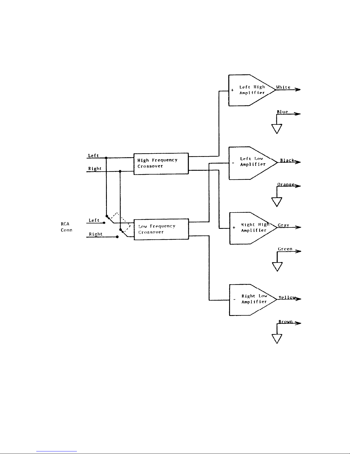
The Amplifier Block Diagram shows a simplified diagram of the
crossover and amplifier system. In the amplifier blocks, the
input shows a “+” for the non-inverted channels and a “-” for the
inverted channels. Each
“+”
channel can be mated to a
“-”
channel into a bridged speaker load.
SPEAKER IMPEDANCE
The Power 650 MOSFET is designed to drive 2-Ohm minimum
speaker loads on each of its four channels, or 4-Ohm minimum
loads when used in Bridged mode (two amplifier sections
driving the same speaker). A 2-Ohm load is formed by
paralleling two 4-Ohm speakers or four 8-Ohm speakers. Of
course, higher-impedance loads than the minimum are entirely
acceptable to the amplifier.
Speakers which are isolated from the amplifier by series
capacitors or high-pass crossovers (for instance, tweeters) do
not usually have a large effect on the amplifier load and should
not be considered in calculating load impedance. The 650
DIN
Conn
INPUTS
POWER 650 MOSFET
AMPLIFIER BLOCK DIAGRAM
-5-

MOSFET is also very tolerant of reactive loads, so complex
multiple-element passive crossover systems should pose no
problems if well-designed.
WHY BIAMPLIFY?
For the performance. Biamplified systems can play cleanly at
higher output levels than stereo systems of the same total
power.
For the
convenience. Building a satisfactory crossover system
for woofer-to-midrange crossover frequencies requires large,
expensive inductors and capacitors, as well as design time and
mounting problems. With a biamplified system it’s all done for
you in the active crossover.
Biamplified systems consist of an active (electronic) crossover
system and two stereo amplifiers. The crossover separates the
input signal into low and high-frequency groups and sends each
group of frequencies to a separate amplifier pair. In most
installations, the low-frequency amplifiers drive a pair of
woofers and the high-frequency amplifiers drive a
midrange-
tweeter pair.
In ordinary stereo systems, as the output level increases, the
low-frequency, high-power notes of the music start to drive the
amplifier into clipping. When the bass (drums, rhythm, etc.)
start to overload the amplifier, all higher frequencies are
naturally clipped as well, so midrange distortion is immediately
audible. The harshness and “gargling“ effects of clipping are
obnoxious to listen to and may destroy tweeters.
In a well-designed biamplified system, when the low frequencies
start to clip only the low-frequency amplifiers overload. The
high-frequency amplifiers are still reproducing the music
cleanly. Harshness and other overload effects are not heard in
the middle and high frequencies until the high-frequency
amplifiers clip, at a much higher level. The worst effects of the
bass amplifiers’ clipping will usually not be audible, since the
woofers won’t reproduce the high-frequency harmonics of the
clipped drive, and the clean middle and high frequencies cover
the low-frequency blurring and muddiness of the bass.
We have found that, for crossover frequencies up to about 600
Hertz, it is best to use approximately equal power for the low and
-6-

high frequency amplifiers of biamplified systems. If the highfrequency amplifiers are significantly lower in power, the highs
will clip before bass distortion is audible, and much of the bass
power capability will be wasted.
Triamplifying; that is, using another active crossover and stereo
amplifier to run the tweeters only, is technically interesting but
less cost-effective. For one thing, there is little or no masking
effect from the very high frequencies for midrange distortion, so
the biggest performance advantage of multiple-amp systems
isn’t available. Crossover components for passive midrange-totweeter crossovers are reasonably small and inexpensive.
Running a separate tweeter amp system will prevent tweeter
burnout due to heavy midrange clipping, and this is the most
substantial advantage of triamplified systems.
SPEAKER POWER RATINGS
The Power 650 MOSFET is a very high-powered amplifier, and
special care must be taken to be sure that the speakers can
handle the power level. Speaker manufacturers’ recommendations for power levels and crossover frequencies should be
observed. The power capacity required for speakers corresponds to the rated output of the amplifier and the mode of
operation. Minimum output into various loads is shown below:
MODE 4-Ohm Speaker 8-Ohm Speaker
Stereo
125 Watts 75 Watts
Bridged 325 Watts 250 Watts
Woofers with high power ratings sometimes “pop”, “clang”,
“snap”, or otherwise show signs of bottoming. These speakers
are designed to use the “air spring” of an enclosed box to
prevent bottoming at high power inputs. This applies to most
woofers originally designed for home or professional use. One
solution is to use speakers designed for “infinite baffle” use,
which have very stiff suspensions. The best solution is to build
boxes for the woofers.
As with woofers, midrange drivers’ power capabilities are
determined by voice coil and suspension design. The most
common power-handling problems for mid-ranges arise when
they are crossed over at too low a frequency or with too shallow
a crossover slope. For every doubling of the crossover
-7-
 Loading...