

Rockford Fosgate Power 360, Power 650 Installation Manual

INSTALLATION MANUAL
FOR
ROCKFORD
FOSGATE
POWER 360
AND
POWER 650
Rockford
Corporation
613 South
Rockford Drive
Tempe
Arizona
85281
(602) 967-3565

INDEX
Introduction .............................................
1
Amplifier Features .......................................
2
System Flexibility ........................................
3
Amplifier Bridging .......................................
4
Amplifier Block Diagram .................................
5
Why Biamplify?
.........................................
6
Speaker Impedance
.....................................
7
Speaker Wire
............................................
7
Power Ratings
...........................................
8
Piezoelectric Tweeters
...................................
8
Crossover System .......................................
9
Using the Crossovers ...................................
10
Crossover Settings .....................................
11
Crossover Response Curves ............................
12
Amplifier Power Wiring .................................
13
DIN Interconnect Cable .................................
14
Input Mode Switch .....................................
14
Turn-on Connection ....................................
15
Mounting the 360 .......................................
15
Power 650 Specifications
...............................
17
Power 360 Specifications ...............................
18
Biamplified Mode Wiring Diagram .......................
19
Power 6501360 Stereo Biamplified Mode Wiring Diagram . 19
Biamplified Stereo Diagram .............................
20
Biamplified Stereo Bridged Mono Woofer Diagram
.......
21
Dual Stereo Diagram ...................................
22
Bridged Stereo Diagram ................................
23
Bridged Mono Biamplified Diagram ......................
24

INTRODUCTION
The Power 650 and Power 360 are state-of-the-art 4 channel
power amplifiers for cars, vans, or wherever a
12-volt
battery is
available.
The amplifiers are designed to be used with a Rockford-Fosgate
equalizer/pre-amplifier
and any high-quality radio, tape, or
other music source. There are several
equalizer/pre-amplifier
units available, including the ZX, and Z, and the 250 preamp.
The Power 650 will provide 325 watts per channel (stereo) and
incorporates a variable-speed fan and shroud assembly for
cooling.
The Power 360 provides 180 watts per channel (stereo) and
is
cooled by a finned heatsink.
Both the Power 650 and Power 360 offer exceptional flexibility in
system design. With switchable crossovers and four bridgeable
power amplifier channels, biamplified systems, high-powered
bridged systems, combinations, and four-channel systems are
easy to put together. Both amplifiers are stable into 2-ohm
loads, or 4-ohm loads when bridged.
Protection circuitry in the amplifiers prevent damage due to
shorts, system power problems, or internal failures. They
incorporate internal battery line filtering and extensive noise
prevention circuitry.
The Power 650 and Power 360 are designed to be
professionally
installed. The length and nature of your warranty are dramatically
affected if you attempt to install it yourself (See Warranty).
This is because professional installers are experienced with
making your car sound right the first time. Professional
installers make their installations durable because they don’t
want continuing problems and complaints - their reputations
are valuable.
If you want to install your own unit, read this booklet completely
-
and Good Luck!
-l-

AMPLIFIER FEATURES
The Power 650 and Power 360 are very similar in design. Both
have selectable crossovers, four bridgeable channels, load
protection, independently available bass channels, and noise
rejection circuitry. System wiring for the two amplifiers is
identical.
The Power 650’s variable-speed fan-cooling assembly allows it
to run at higher power and into lower-impedance loads than the
Power 360. With four 4-ohm loads, each channel of the Power
650 puts out 125 watts, while the 360 puts out 90. The Power 650
is rated for four 2-ohm loads, at 160 watts each or two 4-ohm
loads in bridged stereo at 325 watts each. The Power 360 is not
rated for 2-ohm loads, and the bridged output is two 8-ohm
loads at 180 watts each.
-2-

SYSTEM FLEXIBILITY
A combination of switched crossovers and four bridgeable
channels in the Power 650 and Power 360 provide unmatched
system flexibility with simple wiring changes. Some of the
possibilities are:
Biamplified Stereo
-
A pair of channels drives mid and high
frequency speakers; another pair drives woofers. The crossovers are set to separate the input frequencies into high and
low frequencies for each speaker system.
Biamplified Stereo with Bridged Mono Woofer
-
Otherwise
similar to the Biamplified stereo system above, this arrange-
ment bridges the two low channels into a single woofer.
Bridged Stereo
-
Each pair of channels on Left and Right sides
is bridged into a full-range speaker system. The crossovers
are set at Flat position.
Bridged Mono Biamplified -This configuration produces watts
into one mono channel. The high-frequency channel pair is
bridged into midtweeter speaker system and the
lowfrequency pair bridged into a woofer. The crossovers are set
to separate woofer and midrange frequencies.
Dual Stereo
-
With the crossovers set at “Flat” position, the
power amp will act as two separate stereo amplifiers, one
channel pair for rear full range speakers, one for front
fullrange 4-ohm speakers. If only one set of speakers can handle
bass frequencies, the “High” crossover can be set to cut off
the front speakers’ low frequency drive.
All of these system configurations are obtained with simple
wiring variations; there are no special “black boxes” to buy and
the system may be modified at any time.
-3-

AMPLIFIER BRIDGING
Operating an amplifier in the “bridged” or “strapped mono”
mode means driving one speaker or speaker system with two
amplifier channels. Each channel will put out full power into its
half of the speaker load, so the system can drive the speaker with
double the power that a single amplifier channel would be
capable of.
When amplifiers are bridged into a single speaker, each
amplifier “sees” half of the total speaker impedance.
New Rockford-Fosgate amplifiers are designed so that connecting the amplifier for bridged mode is a simple matter of
using the correct speaker leads as shown in the appropriate
system diagram. In these amplifiers, one channel of each pair is
inverted in the amplifier. In normal stereo use, the inverted
channel output is connected to the negative lead of its speaker
load, thus preserving the system’s polarity. In bridged mode, the
inverted channel is connected to the negative lead of the
speaker to be bridged, and the positive lead of the speaker is
connected to the non-inverted channel. This provides the out-
of-phase drives required for bridged operation.
The Power 650 and Power 360 are designed so that the four
amplifier sections can be bridged in several ways. Right and Left
High-Frequency channels can be bridged, the Right High and
Left Low-Frequency channels can be bridged, the Right High
and Right Low channels can be bridged together, and the Left
High and Left Low channels can be bridged. These combinations allow an unmatched flexibility in designing stereo,
biamplified, and hybrid bridged systems.
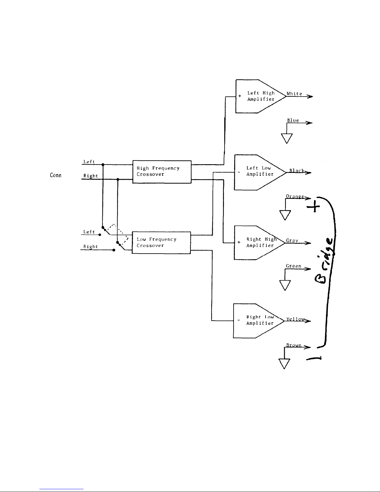
The Amplifier Block Diagram shows a simplified diagram of the
crossover and amplifier system. In the amplifier blocks, the
input shows a “+” for the non-inverted channels and a
“-”
for the
inverted channels. Each “+” channel can be mated to a
“-”
channel into a bridged speaker load.
-4-
DIN
COllfl
INPUTS
RCA
Conn
POWER
650/360
AMPLIFIER BLOCK DIAGRAM
-5-

WHY BIAMPLIFY?
For the performance. Biamplified systems can play cleanly at
higher output levels than stereo systems of the same total
power.
For the convenience. Building a satisfactory crossover system
for woofer-to-midrange crossover frequencies requires large,
expensive inductors and capacitors, as well as design time and
mounting problems. With a biamplified system it’s all done for
you in the active crossover.
Biamplified systems consist of an active (electronic) crossover
system and two stereo amplifiers. The crossover separates the
input signal into low and high-frequency groups and sends each
group of frequencies to a separate amplifier pair. In most
installations, the low-frequency amplifiers drive a pair of
woofers and the high-frequency amplifiers drive a
midrange-
tweeter pair.
In ordinary stereo systems, as the output level increases, the
low-frequency, high-power notes of the music start to drive the
amplifier into clipping. When the bass (drums, rhythm, etc.)
start to overload the amplifier, all higher frequencies are
naturally clipped as well, so midrange distortion is immediately
audible. The harshness and “gargling” effects of clipping are
obnoxious to listen to and may destroy tweeters.
In a well-designed biamplified system, when the low frequencies
start to clip only the low-frequency amplifiers overload. The
high-frequency amplifiers are still reproducing the music
cleanly. Harshness and other overload effects are not heard in
the middle and high frequencies until the high-frequency
amplifiers clip, at a much higher level. The worst effects of the
bass amplifiers’ clipping will usually not be audible, since the
woofers won’t reproduce the high-frequency harmonics of the
clipped drive, and the clean middle and high frequencies cover
the low-frequency blurring and muddiness of the bass.
We have found that, for crossover frequencies up to about 600
Hertz, it is best to use approximately equal power for the low and
high frequency amplifiers of biamplified systems. If the
highfrequency amplifiers are significantly lower in power, the highs
will clip before bass distortion is audible, and much of the bass
power capability will be wasted.
-6-
 Loading...