

Page 1

500bd
1000bd
1500bd
Installation &
Operation
Installation et fonctionnement
Instalación y funcionamiento
Einbau und Betrieb
Installazione e funzionamento
Mono Amplifiers
Page 2

INTRODUCTION
TABLE OF CONTENTS
2
Dear Customer,
Congratulations on your purchase of the world's finest brand of car audio amplifiers. At Rockford
Fosgate we are fanatics about musical reproduction at its best, and we are pleased you chose our
product. Through years of engineering expertise, hand craftsmanship and critical testing procedures,
we have created a wide range of products that reproduce music with all the clarity and richness you
deserve.
For maximum performance we recommend you have your new Rockford Fosgate product installed
by an Authorized Rockford Fosgate Dealer, as we provide specialized training through Rockford
Technical Training Institute (RTTI). Please read your warranty and retain your receipt and original
carton for possible future use.
Great product and competent installations are only a piece of the puzzle when it comes to your
system. Make sure that your installer is using 100% authentic installation accessories from
Connecting Punch in your installation. Connecting Punch has everything from RCA cables and
speaker wire to Power line and battery connectors. Insist on it! After all, your new system deserves
nothing but the best.
To add the finishing touch to your new Rockford Fosgate image order your Rockford accessories,
which include everything from T-shirts and jackets to hats and sunglasses.
To get a free brochure on Rockford Fosgate products and Rockford accessories,
in the U.S. call 480-967-3565 or FAX 480-967-8132.
For all other countries, call +001-480-967-3565 or FAX +001-480-967-8132.
PRACTICE SAFE SOUND™
Continuous exposure to sound pressure levels over 100dB may cause permanent
hearing loss. High powered auto sound systems may produce sound pressure
levels well over 130dB. Use common sense and practice safe sound.
Introduction . . . . . . . . . . . . . . . . . . . . . . . . 2
Safety Instructions . . . . . . . . . . . . . . . . . . . 3
Design Features . . . . . . . . . . . . . . . . . . . . . 4
Installation . . . . . . . . . . . . . . . . . . . . . . . 4-7
Installation Considerations . . . . . . . . . . . 4
Mounting Locations. . . . . . . . . . . . . . . . 5
Battery and Charging . . . . . . . . . . . . . . . 6
Wiring the System . . . . . . . . . . . . . . . . . 6
Remote Punch Bass . . . . . . . . . . . . . . . . 8
NOTE: Review each section for more detailed information.
If, after reading your manual, you still have questions regarding this product, we recommend that
you see your Rockford Fosgate dealer. If you need further assistance, you can call us direct at 1-800669-9899. Be sure to have your serial number, model number and date of purchase available when
you call.
The serial number can be found on the outside of the box. Please record it in the space provided
below as your permanent record. This will serve as verification of your factory warranty and may
become useful in recovering your source unit if it is ever stolen.
Serial Number: _________________________________________
Model Number: ________________________________________
Operation. . . . . . . . . . . . . . . . . . . . . . . . . . 8
Adjusting Gain . . . . . . . . . . . . . . . . . . . 8
Adjusting Crossover Frequency . . . . . . . 8
Applications . . . . . . . . . . . . . . . . . . . . . 9-10
Troubleshooting . . . . . . . . . . . . . . . . . . . . 11
Accessories. . . . . . . . . . . . . . . . . . . . . . . . 11
Specifications . . . . . . . . . . . . . . . . . . . . . . 12
Limited Warranty Information. . . . . . . . . . 13
International Instructions . . . . . . . . . . . . . 14
Page 3

SAFETY INSTRUCTIONS
CONTENTS OF CARTON
3
Visit our web site for the latest information on all Rockford products.
GETTING STARTED
Welcome to Rockford Fosgate! This manual is designed to provide
information for the owner, salesperson and installer. For those of you who want quick information
on how to install this product, please turn to the Installation Section of this manual. Other
information can be located by using the Table of Contents. We, at Rockford Fosgate, have worked
very hard to make sure all the information in this manual is current. But, as we are constantly
finding new ways to improve our product, this information is subject to change without notice.
www.rockfordfosgate.com
This symbol with “WARNING” is intended to alert the user to the
presence of important instructions. Failure to heed the
instructions will result in severe injury or death.
This symbol with “
CAUTION” is intended to alert the user to the
presence of important instructions. Failure to heed the
instructions can result in injury or unit damage.
CAUTION: To prevent injury and damage to the unit, please read and follow the
instructions in this manual. We want you to have enjoyment from this
system, not a headache.
CAUTION If you feel unsure about installing this system yourself, have it installed
by a qualified Rockford Fosgate technician.
CAUTION Before installation, disconnect the battery negative (-) terminal to
prevent damage to the unit, fire and/or possible injury.
!
!
!
Either a model 500bd, 1000bd or 1500bd
Mono Amplifier
Installation & Operation Manual
Mounting Hardware Kit
Remote Punch Bass Kit with Cord
1 3/32" Allen Wrench
1 9/64" Allen Wrench
The hardware kit included with each amplifier contains the mounting hardware necessary to secure
the amplifier to the vehicle and to attach the end caps to the amplifier.
NOTE: Refer to the specifications section for recommended fuse sizes.
Page 4
4
DESIGN FEATURES
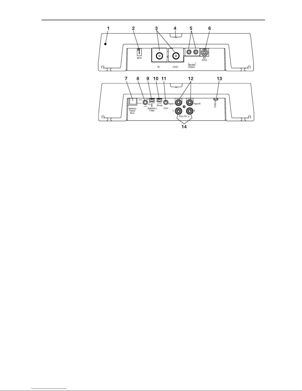
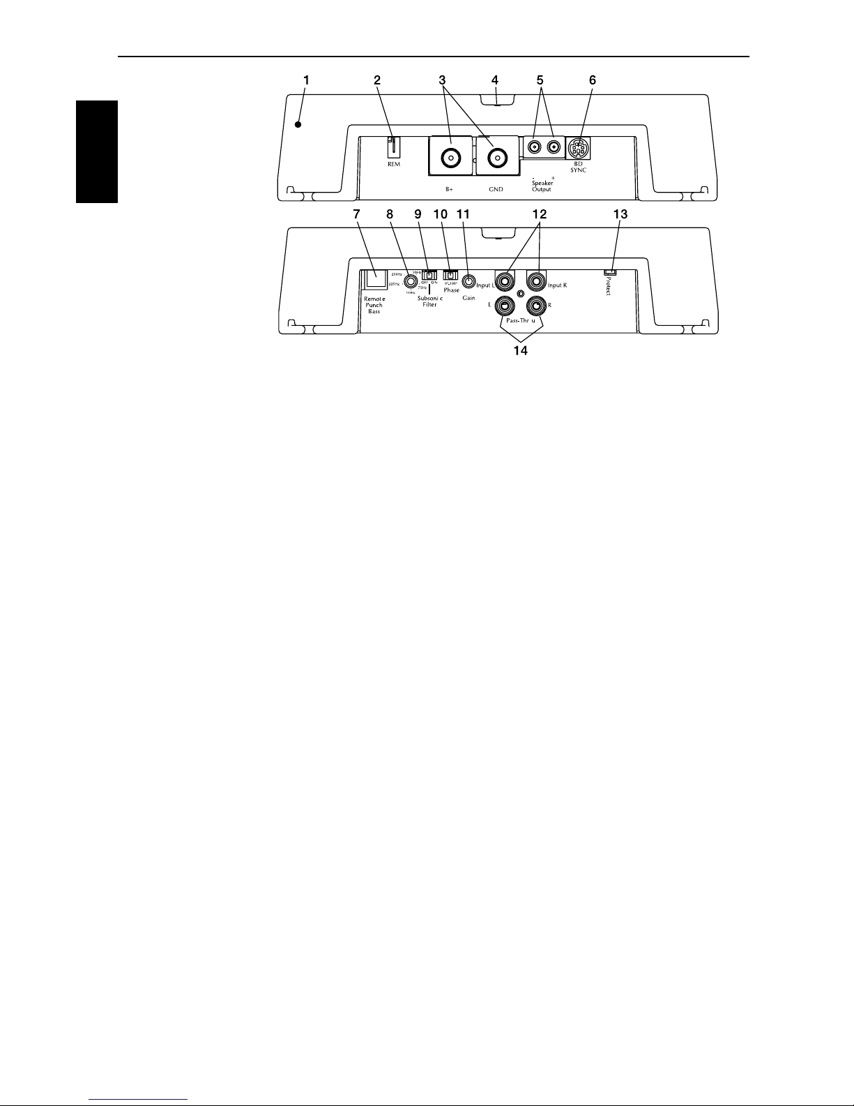
1. Cast Aluminum Heatsink – The cast aluminum heatsink of the amplifier dissipates heat
generated by the amplifier's circuitry. The inherent advantage of casting provides a 30%
improvement of cooling over conventional extrusion heatsink designs.
2.
REM Terminal – This spade terminal is used to remotely turn-on and turn-off the amplifier when
+12V DC is applied.
3. Power Terminals – The power and ground connectors on the amplifier are gold-plated and will
accommodate up to 4 AWG wire maximizing the input current capability of the amplifier.
4. LED Power Indicator – The LED illuminates when the unit is turned on.
5. Speaker Terminals – The heavy duty, gold-plated terminal block connectors (+ and –) will
accept wire sizes from 8 AWG to 18 AWG. These gold-plated connectors are immune to
corrosion that can cause signal deterioration.
6. bd Sync – The amplifiers have a 6 pin mini DIN connector. When operating two amplifiers in
the bridge mode, the SYNC cable must be used. This will allow the two independent frequency
carrier generators in each unit to be synchronized.
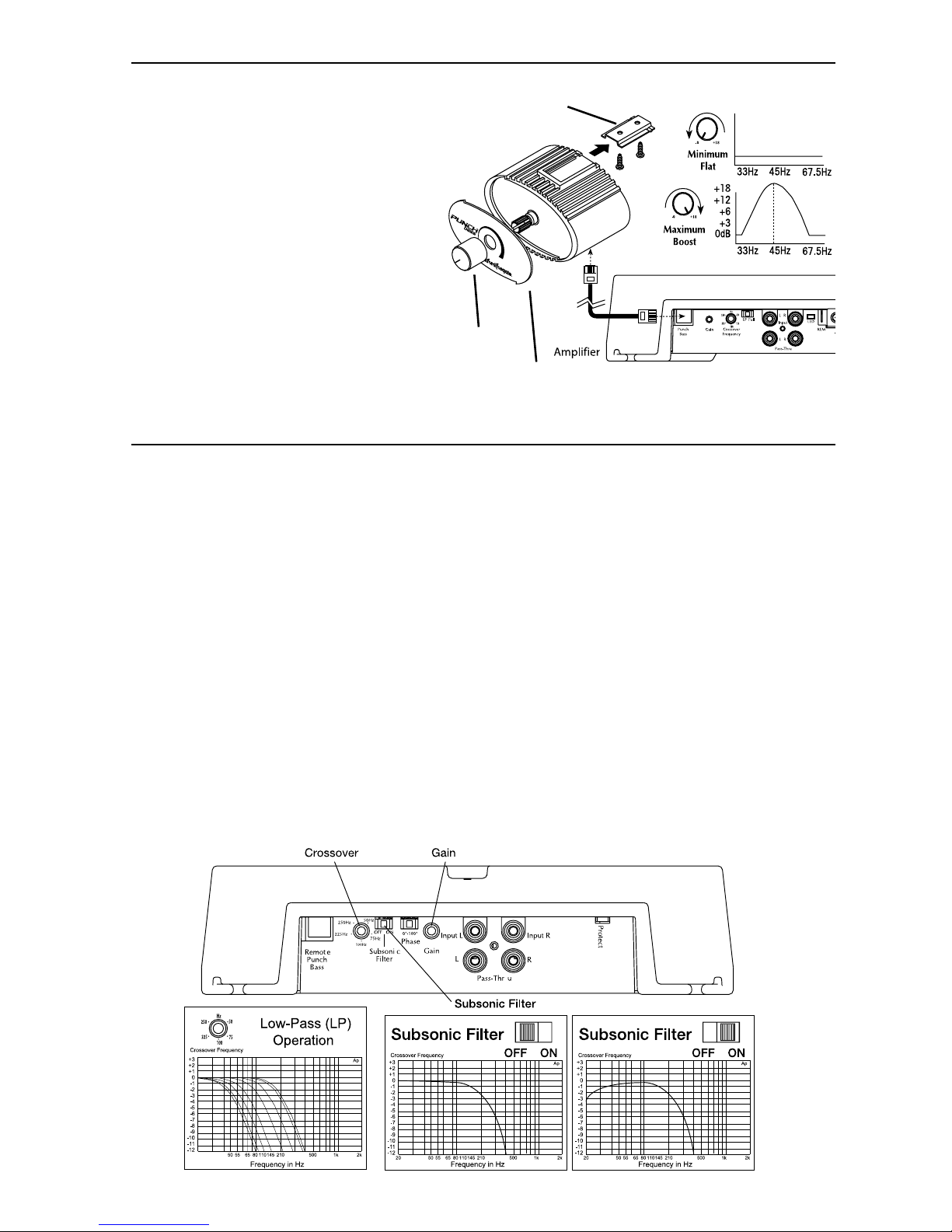
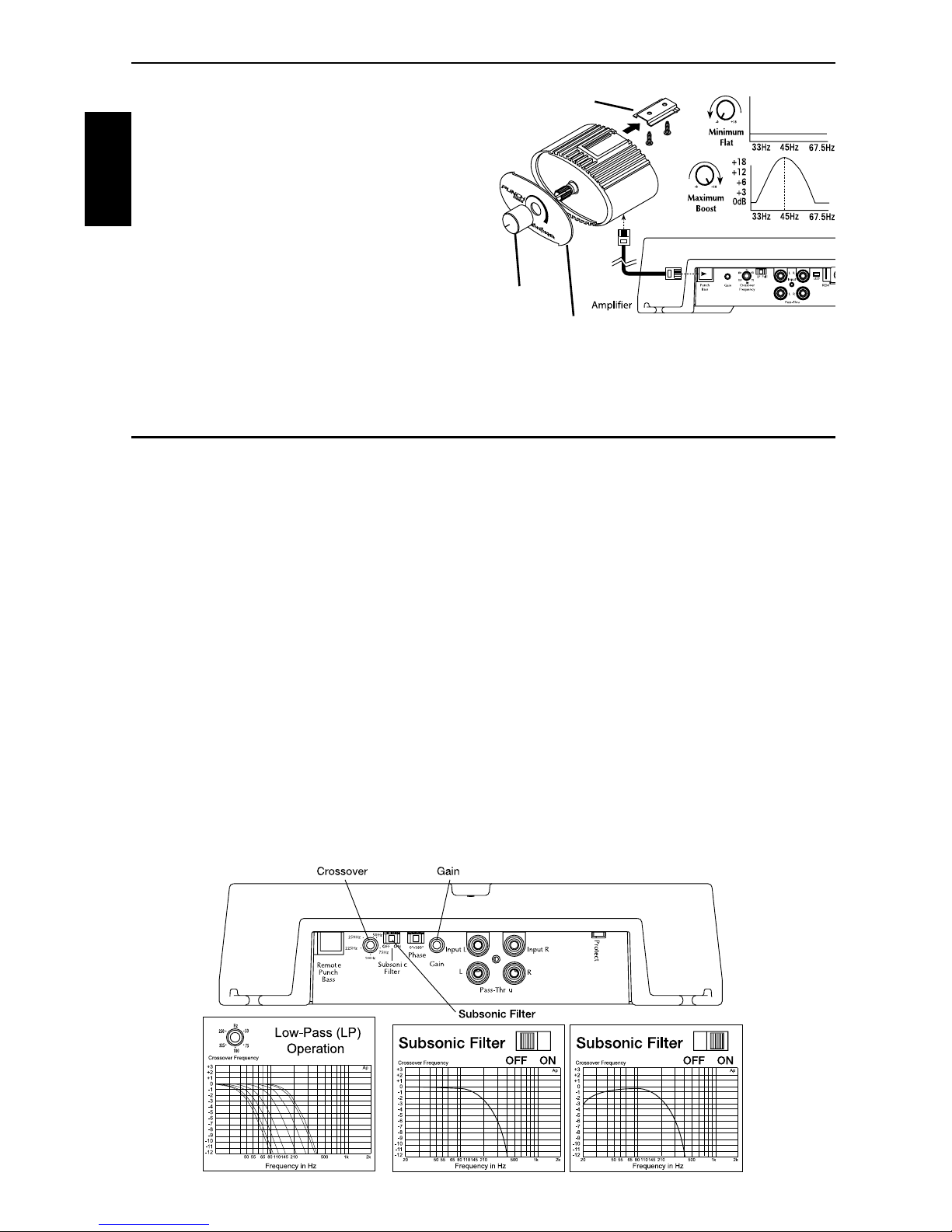
7. Punch Bass – The Punch Bass control helps correct for acoustical deficiencies in the listening
environment by helping produce full range sound without adding excessive boost.. The Punch
Bass control is a narrow band adjustment at 45Hz variable from 0dB to + 18dB. Connection is
made with a cable using RJ-45 and can be installed under the dash for remote control access.
8. Variable Crossover – The amplifiers have a built-in 24dB/octave Butterworth filter with a
crossover point variable from 50Hz to 250Hz. The crossover is set to Low-Pass (LP).
9. Subsonic Filter – A high pass filter designed to prevent frequencies below the audio range from
being applied to the subwoofer from the amplifier. Consequently, improving subwoofer
performance and power handling.
10. Phase – Used when connecting two bd amplifiers together to phase one amplifier 180° from the
other.
11. Gain Control – The input gain control is preset to match the output of most source units. It can
be adjusted to match output levels from a variety of source units.
12. RCA Input Jacks – The industry standard RCA jacks provide an easy connection for signal level
input. They are gold-plated to resist the signal degradation caused by corrosion.
13. Protect LED – The (red) LED illuminates when the unit is latched into protection. It requires
momentary AP removal to enable output PWM.
14. RCA Pass-Thru Jacks – The Pass-Thru provides a convenient source for daisy-chaining an
additional amplifier without running an extra set of RCA cables from the front of the vehicle to
the rear amplifier location.
Power
Connection
Page 5

5
INSTALLA
TION
INSTALLATION CONSIDERATIONS
The following is a list of tools needed for installation:
Volt/Ohm Meter
Wire strippers
Wire crimpers
Wire cutters
#2 Phillips screwdriver
Battery post wrench
Hand held drill w/assorted bits
1/8" diameter heatshrink tubing
Assorted connectors
Adequate Length—Red Power Wire
Adequate Length—Remote Turn-on Wire
Adequate Length—Black Grounding Wire
This section focuses on some of the vehicle considerations for installing your new Amplifier. Preplanning your system layout and best wiring routes will save installation time. When deciding on
the layout of your new system, be sure that each component will be easily accessible for making
adjustments.
CAUTION: If you feel unsure about installing this system yourself, have it installed
by a qualified technician.
CAUTION: Before installation, disconnect the battery negative (-) terminal to
prevent damage to the unit, fire and/or possible injury.
Before beginning any installation, follow these simple rules:
1. Be sure to carefully read and understand the instructions before attempting to install the Unit.
2. For safety, disconnect the negative lead from the battery prior to beginning the installation.
3. For easier assembly, we suggest you run all wires prior to mounting your Source Unit in place.
4. Route all of the RCA cables close together and away from any high current wires.
5. Use high quality connectors for a reliable installation and to minimize signal or power loss.
6. Think before you drill! Be careful not to cut or drill into gas tanks, fuel lines, brake or hydraulic
lines, vacuum lines or electrical wiring when working on any vehicle.
7. Never run wires underneath the vehicle. Running the wires inside the vehicle provides the best
protection.
8. Avoid running wires over or through sharp edges. Use rubber or plastic grommets to protect any
wires routed through metal, especially the firewall.
9. ALWAYS protect the battery and electrical system from damage with proper fusing. Install the
appropriate fuse holder and fuse on the +12V power wire within 18” (45.7 cm) of the battery
terminal.
10. When grounding to the chassis of the vehicle, scrape all paint from the metal to ensure a good,
clean ground connection. Grounding connections should be as short as possible and always be
connected to metal that is welded to the main body, or chassis, of the vehicle.
MOUNTING LOCATIONS
The mounting position of your amplified subwoofer will have a great effect on the sound
performance produced.
Engine Compartment
Never mount this unit in the engine compartment. Mounting the unit in the engine compartment
will void your warranty.
!
!
Page 6

6
INSTALLA
TION
BATTERY AND CHARGING
Amplifiers will put an increased load on the vehicle's battery and charging system. We recommend
checking your alternator and battery condition to ensure that the electrical system has enough
capacity to handle the increased load of your stereo system. Stock electrical systems which are in
good condition should be able to handle the extra load of any Rockford Fosgate amplifier without
problems, although battery and alternator life can be reduced slightly. To maximize the performance
of your amplifier, we suggest the use of a heavy duty battery and an energy storage capacitor.
WIRING THE SYSTEM
CAUTION
: If you do not feel comfortable with wiring your new unit, please see
your local Authorized Rockford Fosgate Dealer for installation.
CAUTION: Before installation, disconnect the battery negative (-) terminal to
prevent damage to the unit, fire and/or possible injury.
CAUTION: Avoid running power wires near the low level input cables, antenna,
power leads, sensitive equipment or harnesses. The power wires carry
substantial current and could induce noise into the audio system.
1. Plan the wire routing. Keep RCA cables close together but isolated from the amplifier's power
cables and any high power auto accessories, especially electric motors. This is done to prevent
coupling the noise from radiated electrical fields into the audio signal. When feeding the wires
through the firewall or any metal barrier, protect them with plastic or rubber grommets to
prevent short circuits. Leave the wires long at this point to adjust for a precise fit at a later time.
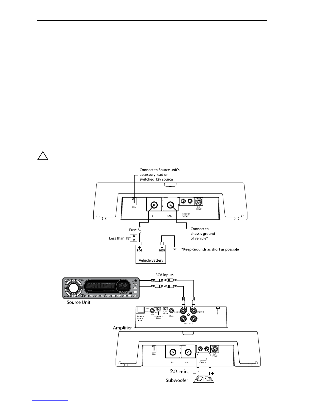
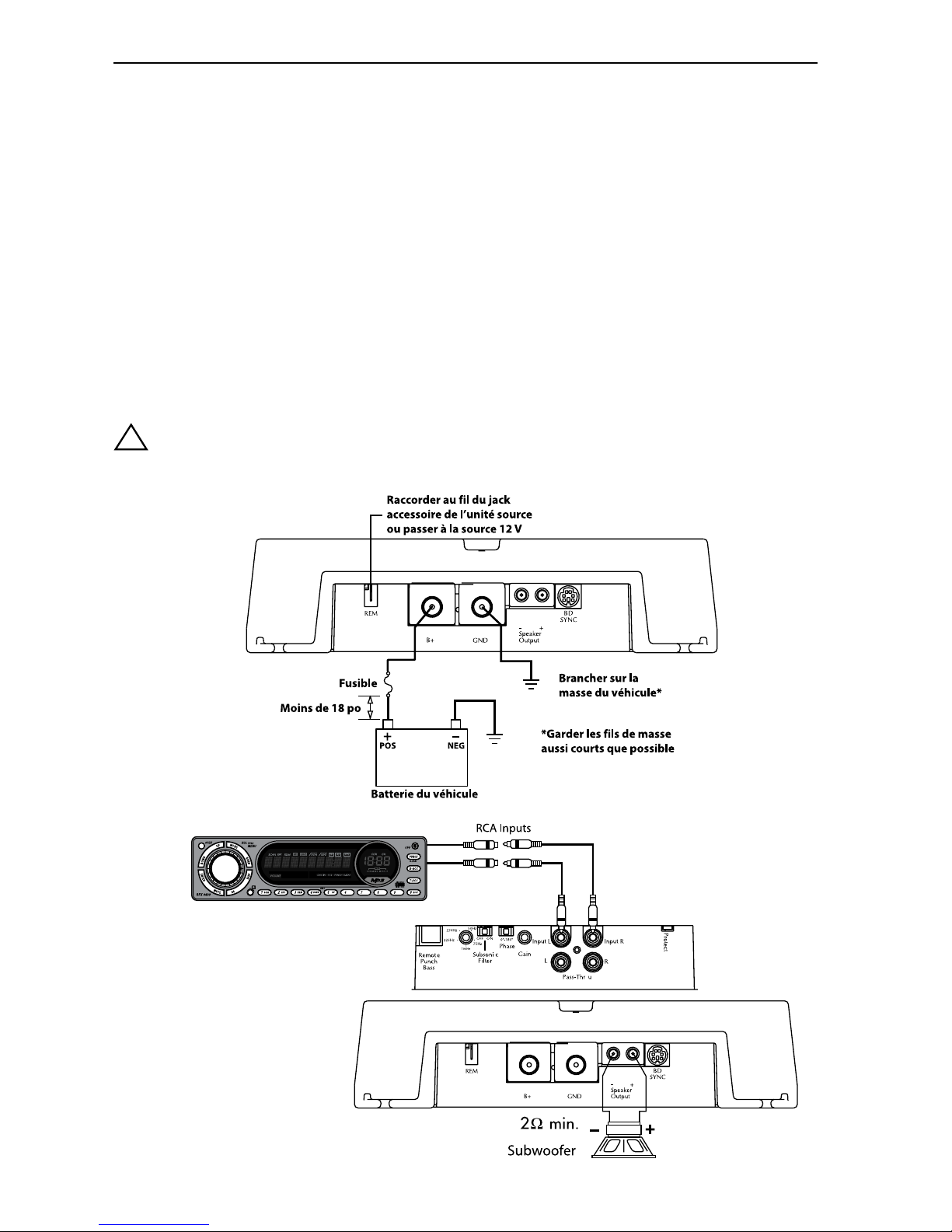
2. Prepare the RED wire (power cable) for attachment to the amplifier by stripping 1/2" of
insulation from the end of the wire. Insert the bared wire into the B+ terminal and tighten the set
screw to secure the cable in place.
NOTE: The B+ cable MUST be fused 18" or less from the vehicle's battery. Install the fuseholder under
the hood and prepare the cable ends as stated above. Connections should be water tight.
3. Trim the RED wire (power cable) within 18" of the battery and strip1/2"of insulation from the
end of the wire. Cut the wire loop that is attached to the fuseholder in half and splice the fuse
into the power line using appropriate inline connectors. Use the section of cable that was
trimmed earlier and connect it to the other end of the fuseholder.
4. Strip 1/2" from the battery end of the power cable and crimp a large ring terminal to the cable.
Use the ring terminal to connect to the battery positive terminal.
DO NOT install the fuse at
this time.
5. Prepare the BLACK wire (Ground cable) for attachment to the amplifier by stripping 1/2" of
insulation from the end of the wire. Insert the bared wire into the GND terminal and tighten the
set screw to secure the cable in place. Prepare the chassis ground by scraping any paint from
the metal surface and thoroughly clean the area of all dirt and grease. Strip the other end of the
wire and attach a ring connector. Fasten the cable to the chassis using a non-anodized screw
and a star washer.
!
!
!
Trunk Mounting
Mounting the amplifier vertically will provide the best cooling of the amplifier.
Mounting the amplifier on the floor of the trunk will work but provides less cooling capability than
vertical mounting.
Mounting the amplifier upside down to the rear deck of the trunk will not provide proper cooling
and will severely affect the performance of the amplifier and is strongly not recommended.
Passenger Compartment Mounting
Mounting the amplifier in the passenger compartment will work as long as you provide a sufficient
amount of air for the amplifier to cool itself. If you are going to mount the amplifier under the seat
of the vehicle, you must have at least 1" (2.54cm) of air gap around the amplifier's heatsink.
Mounting the amplifier with less than 1" (2.54cm) of air gap around the amplifier's heatsink in the
passenger compartment will not provide proper cooling and will severely affect the performance of
the amplifier and is strongly not recommended.
Page 7
7
INSTALLA
TION
6. Prepare the REM turn-on wire for connection to the amplifier by stripping 1/2" of insulation from
the wire end. Insert the bared wire into the REM terminal and tighten the set screw to secure the
cable into place. Connect the other end of the REM wire to a switched 12 volt positive source.
The switched voltage is usually taken from the source unit's accessory lead. If the source unit
does not have this output available, the recommended solution is to wire a mechanical switch
in line with a 12 volt source to activate the amplifier.
7. Securely mount the amplifier to the vehicle or amp rack. Be careful not to mount the amplifier
on cardboard or plastic panels. Doing so may enable the screws to pull out from the panel due
to road vibration or sudden vehicle stops.
8. Connect the source signal to the amplifier by plugging the RCA cables/high level inputs into the
input jacks at the amplifier.
9. Connect the speakers. Strip the speaker wires 1/2" and insert into the speaker terminal and
tighten the set screw to secure into place. Be sure to maintain proper speaker polarity. DO NOT
chassis ground any of the speaker leads as unstable operation may result.
10. Perform a final check of the completed system wiring to ensure that all connections are
accurate. Check all power and ground connections for frayed wires and loose connections
which could cause problems.
NOTE: Follow the diagrams for proper signal polarity.
CAUTION: These amplifiers are not recommended for impedance loads below 2Ω.
!
Page 8
8
REMOTE PUNCH BASS
Mounting and installation
1. Find a location, either under the dash or
near the center console, that gives easy
access to the remote.
2. Using the screws supplied, install the
mounting clip with the tabs towards t
he back.
3. Route the cable for the remote and
connect to both the remote and
amplifed subwoofer.
4. Slip the remote onto the mounting clip
until it snaps into place.
5. Install the decal and knob onto the
remote.
Mounting
Clip
Knob
Decal
INSTALLA
TION
OPERATION
ADJUSTING GAIN
To adjust the gain setting, turn the amplifier gains all the way down. Turn the source unit volume up
until distortion is audible and then turn it down a bit until the distortion is inaudible. This will be
about two thirds all the way up on most source units. Next, turn the amplifier gain setting until once
again distortion is audible and then back it down until the distortion is inaudible. Rockford Fosgate
source units do not distort, so the volume can be used at maximum setting.
NOTE: For a more in depth setting procedure, contact Rockford Technical Support.
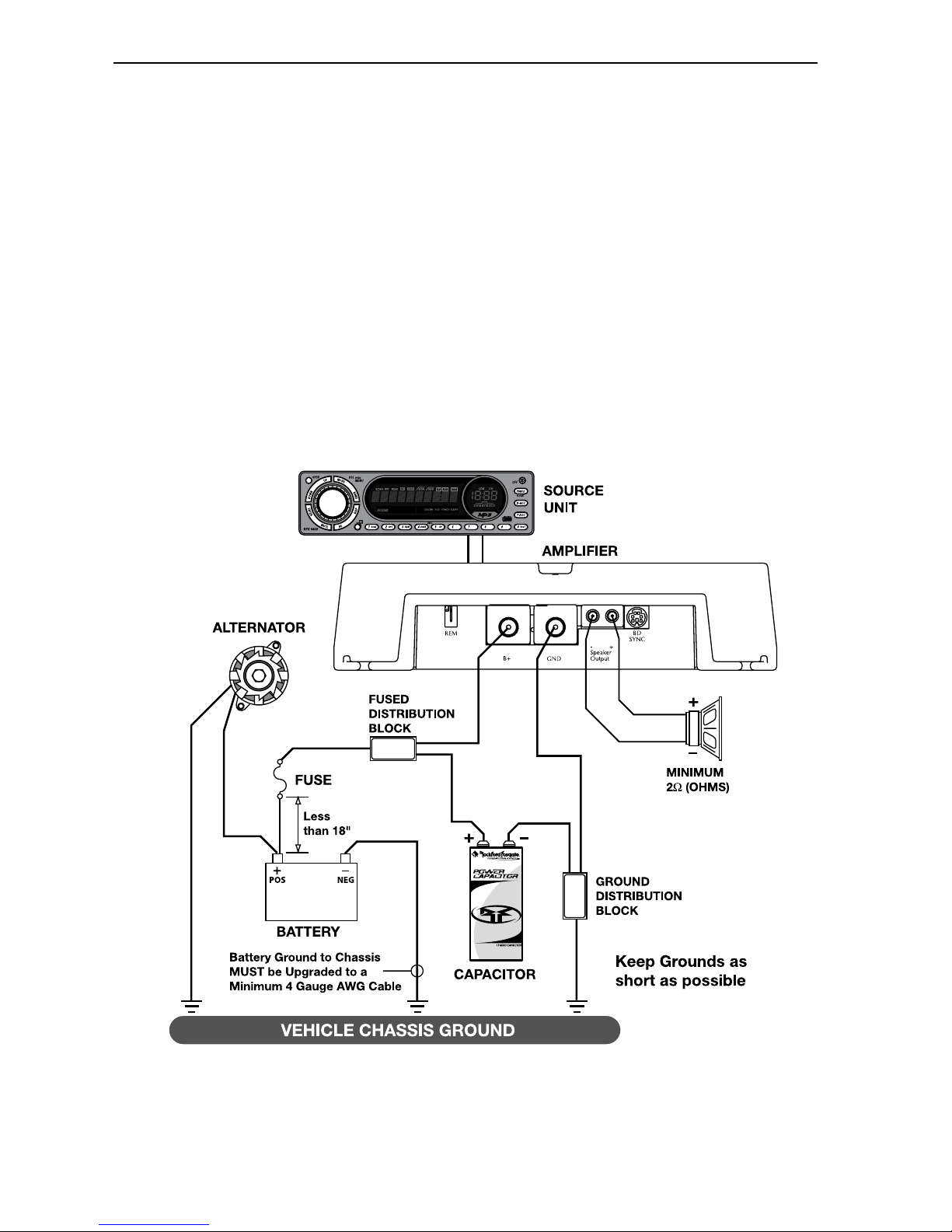
ADJUSTING CROSSOVER FREQUENCY
The crossover frequency can be adjusted between 50-250Hz. The crossover is set to LP (Low Pass)
operation only.
Turn the crossover adjustment knob all the way down. With the system playing, turn the crossover
adjustment knob up slowly until the desired crossover point is achieved.
SUBSONIC FILTER
Placing the switch to "ON" engages a subsonic filter limiting the amount of low frequency
information going to the woofer. Set this to your personal preference while listening to the system
one way, then the other.
Page 9
9
APPLICATIONS
RECOMMENDED CONFIGURATION FOR 0NE (1) AMPLIFIER
MODEL 500bd 1000bd 1500bd
Operational Voltage Range (DC Volts) 10 – 15.5 10 – 15.5 10 – 15.5
Minimum Speaker Impedance 2Ω (Ohms) 2Ω (Ohms) 2Ω (Ohms)
Typical Current Draw (Music) (Amps) 30A 50A 90A
Typical Current Draw (Sine Waves) (Amps) 50A 80A 140A
Recommended Alternator Size
(Street Driven Car) (Amps) 50A 75A 100A
Recommended Alternator Size
(Competition Car) (Amps) 100A 150A 200A
Recommended Power & Gound Wire Size
(AWG – American Wire Gauge) 8 Gauge 4 Gauge 4 Gauge
Recommended Capacitor Size .5 Farad 1 Farad 1.5 Farad
Page 10
10
APPLICATIONS
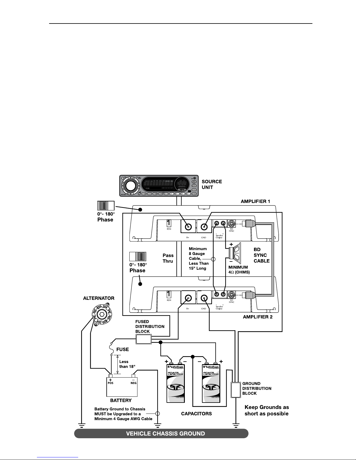
RECOMMENDED CONFIGURATION FOR TWO (2) AMPLIFIERS
MODEL (2) 500bd (2) 1000bd (2) 1500bd
Operational Voltage Range (DC Volts) 10 – 15.5 10 – 15.5 10 – 15.5
Minimum Speaker Impedance 4Ω (Ohms) 4Ω (Ohms) 4Ω (Ohms)
Typical Current Draw (Music) (Amps) 60A 100A 180A
Typical Current Draw (Sine Waves) (Amps) 100A 160A 280A
Recommended Alternator Size
(Street Driven Car) (Amps) 75A 100A 200A
Recommended Alternator Size
(Competition Car) (Amps) 150A 150A 200A
Recommended Power & Gound Wire Size
(AWG – American Wire Gauge) 4 Gauge 2 Gauge 1/0 Gauge
Recommended Capacitor Size 1 Farad 2 Farad 4 Farad
Page 11

11
TROUBLESHOOTING
ACCESSORIES
NOTE: If you are having problems after installation follow the Troubleshooting procedures below.
Procedure 1: Check Amplifier for proper connections.
Verify that POWER light is on. If POWER light is on skip to Step 2, if not continue.
1. Check in-line fuse on battery positive cable. Replace if necessary.
2. Verify that Ground connection is connected to clean metal of the vehicle’s chassis.
Repair/replace if necessary.
3. Verify there is 10.5 - 15.5 Volts of current present at the positive battery and remote turn-on
cable. Verify quality connections for both cables at amplifier, stereo, and battery/fuseholder.
Repair/replace if necessary.
Procedure 2: Check Amplifier for audio output.
1. Verify good RCA/high-level input connections at stereo and amplifier. Check entire length of
cables for kinks, splices, etc. Test RCA/high-level inputs for AC current with stereo on.
Repair/replace if necessary.
2. Disconnect RCA/high-level input from amplifier. Connect RCA/high-level input from test stereo
directly to amplifier input.
Procedure 3: Check Amplifier if you experience Turn-on Pop.
1. Disconnect input signal to amplifier and turn amplifier on and off.
2. If the noise is eliminated, connect the REM lead of amplifier to source unit with a delay turn-on
module.
OR
1. Use a different 12 Volt source for REM lead of amplifier (i.e. battery direct).
2. If the noise is eliminated, use a relay to isolate the amplifier from noisy turn-on output.
Procedure 4: Check Amplifier if you experience excess Engine Noise.
1. Route all signal carrying wires (RCA, Speaker cables) away from power and ground wires.
OR
2. Bypass any and all electrical components between the stereo and the amplifier(s). Connect
stereo directly to input of amplifier. If noise goes away the unit being bypassed is the cause of
the noise.
OR
3. Remove existing ground wires for all electrical components. Reground wires to different
locations. Verify that grounding location is clean, shiny metal free of paint, rust etc.
OR
4. Add secondary ground cable from negative battery terminal to the chassis metal or engine block
of vehicle.
OR
5. Have alternator and battery load tested by your mechanic. Verify good working order of vehicle
electrical system including distributor, spark plugs, spark plug wires, voltage regulator etc.
Connecting PUNCH Capacitors
Maintain the power you need to your Power Amplifier.
Connecting Links
Mount your Power Amplifiers together for space reduction and a smooth look.
See our website for other accessories to help you get the most out of your system.
www.rockfordfosgate.com
Page 12

12
SPECIFICATIONS
Specifications subject to change without notice
MODEL- Power 500bd 1000bd 1500bd
Continuous Power Rating (RMS) - Measured at 14.4 Battery Volts
4Ω Load Mono 300 Watts x 1 500 Watts x 1 750 Watts x 1
2Ω Load Mono 600 Watts x 1 1000 Watts x 1 1500 Watts x 1
Dimensions: (with Endbell)
Height 2.4" (6.1cm) 2.4" (6.1cm) 2.4" (6.1cm)
Width 9.8" (24.89cm) 9.8" (24.89cm) 9.8" (24.89cm)
Length 13.35" (33.96cm) 13.35" (33.96cm) 18.35" (46.74cm)
Battery Fuse Rating (Amp) 50A 100A 1500A
(External to Amplifier) Not Supplied Not Supplied Not Supplied
Fuse Type AGU AGU AGU
Signal-to-Noise Ratio >100dB A-weighted
Crossover Slope 24dB/octave Butterworth
Crossover Frequency variable LP (Low Pass) from 50Hz to 250Hz
Frequency Response 20Hz to 20kHz ±0.5dB
Bandwidth 20Hz to 200kHz ±3dB
Damping Factor @ 4Ω (at output connector ) >200
Slew Rate 30 Volts/ms
IM Distortion (IHF) <0.05%
Acceptable Signal Voltage Range Variable from 250mV to 6V (RCA Input)
Protection NOMAD - Internal analog-computer output protection
circuitry limits power in case of overload. Thermal
switch shuts down the amplifier in case of overheating.
Equalization (45Hz Punch Bass) Variable from 0dB to +18dB @ 45Hz
Input Impedance 20k ohms
Page 13

13
Ship to: Electronics
Rockford Corporation
Warranty Repair Department
2055 E. 5th Street
Tempe, AZ 85281
RA#: _________________________
Ship to: Speakers
Rockford Acoustic Design
Speaker Returns
2356 Turner Ave. NW
Grand Rapids, MI 49544
RA#: ____________________
LIMITED WARRANTY INFORMATION
Rockford Corporation offers a limited warranty on Rockford Fosgate products on the
following terms:
Length of Warranty
PUNCH Amplifiers – 2 years All Other Amplifier Models – 3 years
Source Units – 1 year Speakers – 1 year
90 days on speaker, amplifier and source unit B-stock (receipt required)
What is Covered
This warranty applies only to Rockford Fosgate products sold to consumers by Authorized
Rockford Fosgate Dealers in the United States of America or its possessions. Product
purchased by consumers from an Authorized Rockford Fosgate Dealer in another country
are covered only by that country’s Distributor and not by Rockford Corporation.
Who is Covered
This warranty covers only the original purchaser of Rockford product purchased from an
Authorized Rockford Fosgate Dealer in the United States. In order to receive service, the
purchaser must provide Rockford with a copy of the receipt stating the customer name,
dealer name, product purchased and date of purchase.
Products found to be defective during the warranty period will be repaired or replaced
(with a product deemed to be equivalent) at Rockford's discretion.
What is Not Covered
1. Damage caused by accident, abuse, improper operations, water, theft
2. Any cost or expense related to the removal or reinstallation of product
3. Service performed by anyone other than Rockford or an Authorized Rockford Fosgate
Service Center
4. Any product which has had the serial number defaced, altered, or removed
5. Subsequent damage to other components
6. Any product purchased outside the U.S.
7. Any product not purchased from an Authorized Rockford Fosgate Dealer
Limit on Implied Warranties
Any implied warranties including warranties of fitness for use and merchantability are
limited in duration to the period of the express warranty set forth above. Some states do not
allow limitations on the length of an implied warranty, so this limitation may not apply. No
person is authorized to assume for Rockford Fosgate any other liability in connection with
the sale of the product.
How to Obtain Service
Please call 1-800-669-9899 for Rockford Customer Service. You must obtain an RA#
(Return Authorization number) to return any product to Rockford Fosgate. You are
responsible for shipment of product to Rockford.
EU Warranty
This product meets the current EU warranty requirements, see your Authorized dealer for
details.
Page 14

2
Français
INTRODUCTION
TABLE DES MATIÈRES
Cher client,
Toutes nos félicitations pour avoir acheté la meilleure marque d'amplificateurs pour automobile.
Chez Rockford Fosgate nous sommes des mordus de la reproduction musicale à son meilleur. C’est
pourquoi nous sommes heureux que vous ayez choisi notre produit. Des années d’expertise en
ingénierie, de savoir-faire et d’essais poussés nous ont permis de créer une vaste gamme de produits
capables de reproduire toute la clarté et la richesse musicales que vous méritez.
Pour obtenir les meilleurs résultats, nous vous recommandons de faire installer votre nouvel appareil
par un distributeur agréé Rockford Fosgate formé spécialement par notre Institut de formation
technique Rockford (RTTI). Prenez soin de lire la garantie et conservez votre reçu ainsi que
l’emballage d'origine pour usage ultérieur.
Pour monter un excellent système, il ne suffit pas de posséder un super produit et d’assurer une
installation qualifiée compétente. Vous devez veiller à ce que votre installateur utilise des
accessoires d’origine fournis par Connecting Punch. Connecting Punch a tout ce qu’il vous faut, des
câbles RCA aux câbles de haut-parleurs, en passant par les câbles d’alimentation et les connecteurs
de batterie. Insistez pour les avoir! Après tout, votre nouveau système ne mérite rien de moins.
Pour compléter votre nouvelle image Rockford Fosgate, commandez des accessoires Rockford tels
que T-shirts, vestes, chapeaux et lunettes de soleil.
Pour obtenir une brochure gratuite sur les produits Rockford Fosgate et les accessoires Rockford,
appelez aux États-Unis le 480-967-3565 ou faxez au 480-967-8132.
Pour tous les autres pays, appelez le +001-480-967-3565 ou faxez au +001-480-967-8132.
PRATIQUEZ UNE ÉCOUTE SANS RISQUES
MD
Une exposition continue à des niveaux de pression acoustique supérieurs à 100 dB
peut causer une perte d'acuité auditive permanente. Les systèmes audio de forte
puissance pour auto peuvent produire des niveaux de pression acoustique bien au-
delà de 130 dB. Faites preuve de bon sens et pratiquez une écoute sans risques.
NOTE : consultez chaque section pour de plus amples informations.
Si vous avez encore des questions à propos de ce produit, même après avoir lu ce manuel,
contactez votre distributeur agréé Rockford Fosgate. Si vous avez besoin d'aide, appelez-nous au
1-800-669-9899. Veuillez avoir les numéros de modèle et de série, ainsi que la date d'achat de
l'appareil à portée de main lorsque vous appelez.
Le numéro de série est indiqué sur l’extérieur de l’emballage. Veuillez l’inscrire ci-dessous dans
l'espace réservé à cet effet. Il permettra de vérifier votre garantie et de retrouver votre appareil en
cas de vol.
Numéro de série :_______________________________________
Numéro de modèle : ____________________________________
Introduction . . . . . . . . . . . . . . . . . . . . . . . . 2
Consignes de sécurité . . . . . . . . . . . . . . . . . 3
Particularités techniques. . . . . . . . . . . . . . . 4
Installation . . . . . . . . . . . . . . . . . . . . . . . 4-7
Considérations concernant l'installation . 4
Emplacements de montage . . . . . . . . . . 5
Batterie et charge . . . . . . . . . . . . . . . . . 6
Câblage du système. . . . . . . . . . . . . . . . 6
Basses Punch à télécommande. . . . . . . . 8
Fonctionnement . . . . . . . . . . . . . . . . . . . . . 8
Réglage du gain . . . . . . . . . . . . . . . . . . 8
Réglage de la fréquence du filtre . . . . . . 8
Applications . . . . . . . . . . . . . . . . . . . . . 9-10
Dépannage . . . . . . . . . . . . . . . . . . . . . . . . . 9
Accessoires. . . . . . . . . . . . . . . . . . . . . . . . . 9
Caractéristiques . . . . . . . . . . . . . . . . . . . . 10
Garantie limitée . . . . . . . . . . . . . . . . . . . . 11
Page 15
3
CONSIGNES DE SÉCURITÉ
CONTENU DE L'EMBALLAGE
AVANT DE COMMENCER
Bienvenue à Rockford Fosgate! Ce manuel vise à informer le propriétaire, le vendeur et l’installateur de
l’appareil. Si vous désirez apprendre rapidement comment installer ce produit, consultez la section
Installation du manuel. Reportez-vous à la Table des matières pour d’autres informations. Nous nous
efforçons de faire en sorte que toutes les informations contenues dans ce manuel soient à jour. Mais
comme nous améliorons constamment nos produits, nous nous réservons le droit de modifier ces
informations sans aucun préavis.
Le symbole accompagnant le mot « AVERTISSEMENT » signale à
l'utilisateur la présence d’instructions importantes. Le non-respect
de ces instructions causera des blessures graves ou la mort.
Le symbole accompagnant l’expression «
MISE EN GARDE »
signale à l'utilisateur la présence d’instructions importantes. Le
non-respect de ces instructions peut causer des blessures ou
endommager l’appareil.
MISE EN GARDE : pour éviter des blessures et ne pas endommager l'appareil,
veuillez lire et suivre les instructions du manuel. Notre but est
que ce système vous donne du plaisir et non des maux de tête.
MISE EN GARDE : si vous vous sentez incapable d’installer l’appareil vous-même,
confiez la tâche à un technicien Rockford Fosgate qualifié.
MISE EN GARDE : avant d'entamer l'installation, déconnectez la broche négative (-)
de la batterie pour éviter tout risque de blessures, d’incendie ou
de dommages à l'appareil.
!
!
!
Visitez notre site Web pour obtenir les dernières informations sur tous les produits Rockford.
www.rockfordfosgate.com
Amplificateur mono modèle 500bd,
1000bd ou 1500bd
Manuel d'installation et d'utilisation
Kit de matériel de montage
Kit de télécommande de basses Punch
avec cordon
1 clé Allen 3/32 po
1 clé Allen 9/64 po
Le kit de matériel inclus avec chaque amplificateur contient le matériel de montage nécessaire pour
fixer l'ampli au véhicule et les couvercles d'extrémité à l'ampli.
REMARQUE : reportez-vous à la section des caractéristiques en ce qui concerne les fusibles recommandés.
Page 16
4
Français
PARTICULARITÉS TECHNIQUES
1. Dissipateur thermique en aluminium coulé – Le dissipateur thermique en aluminium coulé de
l'amplificateur Power dissipe la chaleur générée par les circuits de l'amplificateur. L'avantage intrinsèque
du moulage est qu'il améliore de 30 % la capacité de refroidissement par rapport aux modèles
conventionnels de dissipateur thermique à extrusion.
3.
Bornes d'alimentation - Les connexions d'alimentation et de masse de l'ampli sont plaquées or et peuvent
accueillir des câbles de calibre allant jusqu'à 4 AWG, ce qui permet de maximiser la capacité de courant
d'entrée de l'ampli.
2.
Borne REM – Cette cosse à fourche permet d'allumer et d'éteindre à distance l'amplificateur lorsqu'un
courant de +12 V c.c. est envoyé.
4.
Voyant d'alimentation à DEL – La DEL s'allume lorsque l'appareil est allumé.
5.
Bornes de haut-parleur – Les connecteurs robustes plaqués or des bornes (+ et -) acceptent des câbles de
calibre 8 à 18 AWG. Ces connecteurs plaqués or sont à l'épreuve de la corrosion qui peut nuire au signal.
6.
bd Sync – Les amplificateurs sont dotés d'un connecteur mini-DIN à 6 broches. Le câble SYNC doit être
utilisé lorsqu'on utilise deux amplis en mode ponté. Cela permet de synchroniser les deux générateurs de
fréquence indépendants de chaque appareil.
7.
Basses Punch – La commande de basses Punch permet de corriger les faiblesses acoustiques de
l'environnement en produisant un son pleine gamme sans amplification excessive. La commande de
basses Punch permet un réglage à bande étroite sur 45 Hz pouvant être commuté de 0 dB à +18 dB. La
connexion se fait à l'aide d'un câble RJ-45 pouvant être installé sous le tableau de bord pour permettre un
accès par télécommande.
8.
Filtre variable - Les amplificateurs sont dotés d'un filtre de Butterworth intégré de 24 dB/octave dont le
point de fréquence varie entre 50 Hz et 250 Hz. Le filtre est réglé sur passe-bas (LP).
9.
Filtre subsonique – Filtre passe-haut conçu pour empêcher la transmission, de l’ampli au subwoofer, des
fréquences inférieures à la plage sonore. Par conséquent, cela améliore le rendement et la puissance du
subwoofer.
10.
Phase – Utilisé lorsqu'on connecte deux amplificateurs bd ensemble pour déphaser un amplificateur de
l'autre de 180°.
11.
Commande de gain – La commande de gain d'entrée est préréglée de manière à correspondre à la sortie
de la plupart des unités source. Elle peut être réglée en fonction d'une variété d'unités source.
12.
Prises d'entrée RCA – Les prises RCA de norme industrielle permettent une connexion facile pour les
entrées de signaux. Elles sont plaquées or pour résister à la détérioration de signal due à l'effet de la
corrosion.
13.
DEL Protect – La DEL rouge s'allume lorsque l'appareil est protégé par verrouillage. Il faut neutraliser
temporairement le filtre AP pour activer la sortie PWM.
14.
Extension ampli RCA – L'extension ampli permet de connecter en guirlande un second ampli en évitant
d'acheminer des câbles RCA supplémentaires de l'avant du véhicule vers l'emplacement de l'ampli
arrière.
Connexion
d'alimentation
Page 17

5
INSTALLA
TION
Cette section traite de points concernant le véhicule dont il faut tenir compte pour l’installation de
votre nouvel ampli. Vous sauverez du temps en planifiant à l’avance la disposition du système et du
câblage. Assurez-vous, entre autres, que chaque composant du système est facilement accessible
pour les réglages.
MISE EN GARDE : si vous vous sentez incapable d’installer l’appareil vous-même,
confiez la tâche à un technicien qualifié.
MISE EN GARDE : avant d'entamer l'installation, déconnectez la broche négative (-)
de la batterie pour éviter tout risque de blessures, d’incendie ou
de dommages à l'appareil.
Avant de commencer l’installation, suivez ces règles toutes simples :
1. Prenez soin de bien lire et comprendre les instructions avant d’installer l’appareil.
2. Par mesure de sécurité, veuillez débrancher le fil négatif de la batterie avant de commencer
l’installation.
3. Pour faciliter le montage, nous vous suggérons de dérouler tous les fils avant d’installer
l’appareil.
4. Acheminez tous les câbles RCA de façon groupée, à l’écart des fils à courant élevé.
5. Utilisez des connecteurs de haute qualité pour assurer une installation fiable et minimiser la
perte de signal ou de puissance.
6. Réfléchissez avant de percer quoique ce soit ! Faites attention de ne pas couper ou percer le
réservoir d’essence, les conduites de carburant, de frein, hydrauliques ou de dépression, ou le
câblage électrique lorsque vous travaillez sur un véhicule.
7. Ne faites jamais passer les fils sous le véhicule. Il vaut mieux les installer à l’intérieur du
véhicule pour assurer une meilleure protection.
8. Évitez de faire passer les fils par dessus ou à travers des bords tranchants. Tout fil acheminé à
travers du métal, un pare-feu en particulier, doit être protégé avec des bagues en caoutchouc ou
plastique.
9. Protégez TOUJOURS la batterie et le circuit électrique des dommages potentiels à l’aide de
fusibles. Installez un porte-fusible et un fusible appropriés sur le câble d’alimentation de +12 V
à moins de 45,7 cm (18”) de la borne de batterie.
10. Préparez la masse du châssis en grattant toute trace de peinture de la surface métallique afin
d’assurer une bonne mise à la masse. Les connexions de masse doivent être aussi courtes que
possible et toujours connectées à du métal soudé à la carrosserie ou au châssis du véhicule.
EMPLACEMENTS DE MONTAGE
L’emplacement de l’ampli influe grandement sur la qualité du son obtenu.
Compartiment moteur
Ne montez jamais cet appareil dans le compartiment moteur. Cela entraînerait l’annulation de la garantie.
!
!
CONSIDÉRATIONS CONCERNANT L’INSTALLATION
Voici la liste d’outils requis pour l’installation :
Voltmètre-ohmmètre
Pince à dénuder
Pince à sertir
Coupe-fils
Tournevis à embout cruciforme n
o
2
Clé de borne de batterie
Perceuse à main avec mèches assorties
Tube thermorétrécissable de 1/8 po de
diamètre
Connecteurs assortis
Longueur adéquate — Fil d’alimentation
rouge
Longueur adéquate — Fil d’allumage à
distance
Longueur adéquate — Fil de masse noir
Page 18

6
Français
INSTALLA
TION
BATTERIE ET CHARGE
Les amplificateurs exercent une charge accrue sur la batterie et le système de charge du véhicule. Nous vous
conseillons de vérifier l’état de l’alternateur et de la batterie pour vous assurer que le système électrique puisse
supporter la charge accrue de votre système stéréo. Les systèmes électriques ordinaires en bon état sont
normalement capables de fournir sans problème la charge supplémentaire requise par les amplis Rockford
Fosgate. Toutefois, la durée de vie de la batterie et de l’alternateur peut s’en trouver affectée légèrement. Pour
maximiser la performance de votre ampli, nous vous suggérons d’utiliser une batterie à usage intensif et un
condensateur de stockage d’énergie.
CÂBLAGE DU SYSTÈME
MISE EN GARDE : si vous ne vous sentez pas à l’aise pour effectuer vous-même le câblage de votre
nouvel appareil, veuillez confier l’installation à votre distributeur agréé Rockford
Fosgate.
MISE EN GARDE : avant d'entamer l'installation, déconnectez la broche négative (-) de la batterie
pour éviter tout risque de blessures, d’incendie ou de dommages à l'appareil.
MISE EN GARDE : évitez de faire passer les fils d’alimentation près des câbles d’entrée bas niveau,
de l’antenne, des câbles d'alimentation, des équipements ou faisceaux sensibles.
Les fils d’alimentation transportent un courant élevé et peuvent produire du bruit
dans le système audio.
1. Planifiez l’acheminement des fils. Gardez les câbles RCA ensemble mais en les isolant des câbles
d’alimentation de l’ampli et des autres accessoires automobiles de forte puissance, particulièrement les
moteurs électriques, pour éviter que le signal audio ne subisse d'interférence de bruit provenant de champs
de rayonnement électriques. Si vous faites passer les fils par un pare-feu ou autre barrière métallique,
protégez-les à l’aide de bagues en caoutchouc ou en plastique pour éviter les courts-circuits. Conservez toute
la longueur des fils pour l’instant. Vous l’ajusterez plus tard.
2. Préparez le fil ROUGE (câble d’alimentation) qui devra être relié à l’ampli en dénudant 1/2 po de son
extrémité. Insérez la partie dénudée dans la borne B+, puis fixez le fil en vissant la vis sans tête.
REMARQUE : le câble B+ DOIT comporter un fusible à 18 pouces ou moins de la batterie du véhicule. Installez le
porte-fusible sous le capot et préparez les extrémités de câble tel qu’indiqué ci-dessus. Les
connexions doivent être étanches.
3. Coupez le fil ROUGE (câble d’alimentation) à moins de 18 pouces de la batterie et dénudez 1/2 po de son
extrémité. Coupez en deux la boucle reliée au porte-fusible et épissez le fusible sur le fil d’alimentation à
l’aide de connecteurs en ligne appropriés. Utilisez la section de fil coupée plus tôt et connectez-la à l’autre
extrémité du porte-fusible.
4. Dénudez 1/2 po de l’extrémité de batterie du câble d’alimentation et sertissez une grosse cosse à anneau sur
le câble. Connectez la cosse à la borne positive de la batterie. N’installez pas le fusible pour l'instant.
5. Préparez le fil NOIR (câble de mise à la masse) qui devra être relié à l’ampli en dénudant 1/2 po de son
extrémité. Insérez la partie dénudée dans la borne GND, puis fixez le fil en vissant la vis sans tête. Préparez
la masse du châssis en grattant toute trace de peinture de la surface métallique et en nettoyant soigneusement
pour éliminer tout dépôt de saleté et de graisse. Dénudez l’autre extrémité du fil et fixez un connecteur en
anneau. Fixez le câble au châssis à l’aide d’une vis non anodisée et une rondelle en étoile.
!!!
Montage dans le coffre
Un montage vertical de l’ampli assure un refroidissement optimal.
Le montage de l’ampli sur le plancher du coffre est acceptable mais offre un refroidissement moindre que
le montage vertical.
Le montage de l’ampli à l’envers, sur la tablette arrière, n’assure pas un refroidissement satisfaisant, nuit à
la performance de l’ampli et est, pas conséquent, fortement déconseillé.
Montage dans l’habitacle
Le montage de l’ampli dans l’habitacle passager est acceptable à condition que l’ampli reçoive
suffisamment d’air pour refroidir. Si vous comptez installer l’ampli sous le siège du véhicule, prévoyez un
écartement d’au moins 2,54 cm (1 po) autour du dissipateur thermique de l’ampli.
Un écartement inférieur à cela n’assure pas un refroidissement satisfaisant, nuit à la performance de l’ampli
et est, pas conséquent, fortement déconseillé.
Page 19
7
INSTALLA
TION
6. Préparez le fil d’activation REM qui devra être relié à l’ampli en dénudant 1/2 po de son extrémité. Insérez la
partie dénudée dans la borne REM, puis fixez le fil en vissant la vis sans tête. Connectez l’autre extrémité du
fil REM à une source positive commutée de 12 volts. La tension commutée provient généralement de
l’antenne ou du câble d’accessoires de la source audio. Si la source audio ne comporte pas de telles sorties,
nous recommandons de raccorder un interrupteur mécanique en ligne avec une source de 12 volts pour
activer l’ampli.
7. Montez solidement l’ampli sur le véhicule ou le rack d’ampli. Prenez soin de ne pas le fixer sur des
panneaux en carton ou en plastique. Les vis pourraient en effet se décoller des panneaux sous l’effet des
vibrations de la route ou des arrêts soudains du véhicule.
8. Connectez le signal à l’ampli en branchant les câbles RCA/entrées haut niveau dans les prises d’entrée de
l’ampli.
9. Connectez les haut-parleurs : dénudez les fils des haut-parleurs de 1/2 po et insérez la partie dénudée dans la
borne du haut-parleur, puis serrez la vis sans tête pour fixer le tout. Veillez à respecter la polarité des hautparleurs. NE mettez PAS les fils de haut-parleur à la masse sur le châssis car cela pourrait causer un
fonctionement instable.
10. Effectuez une vérification finale du câblage pour vous assurer que toutes les connexions sont bien mises.
Vérifiez toutes les connexions d’alimentation et de mise à la masse en vue de fils effilochés et de connexions
desserrées pouvant causer des problèmes.
REMARQUE : vérifiez les polarités de signal à l’aide des schémas.
MISE EN GARDE : ces amplificateurs ne sont pas recommandés pour des charges
d'impédance inférieures à 2 Ω.
!
Source audio
Amplificateur
Page 20
8
Français
FONCTIONNEMENT
RÉGLAGE DU GAIN
Pour régler le gain, tournez le bouton de gain de l’ampli vers son niveau le plus bas. Augmentez le
volume de la source audio jusqu’à produire une distorsion audible, puis baissez-le jusqu’à ce que la
distorsion devienne inaudible. Cela correspondant généralement aux deux tiers du volume sur la
plupart des sources audio. Augmentez ensuite le gain de l’ampli jusqu’à produire de nouveau une
distorsion audible, puis baissez-le jusqu’à ce que la distorsion devienne inaudible. Les sources
audio Rockford Fosgate ne produisent pas de distorsion, vous pouvez donc mettre le volume au
maximum.
REMARQUE : pour un réglage plus approfondi, communiquez avec le support technique de Rockford.
RÉGLAGE DE LA FRÉQUENCE DU FILTRE
La fréquence du filtre peut être ajustée de 50 à 250 Hz. Le filtre est réglé sur un fonctionnement en
mode LP (passe-bas) uniquement.
Baissez complètement le niveau du filtre. Le système audio étant en fonctionnement, augmentez le
niveau du filtre graduellement jusqu'à atteindre le point de fréquence voulu.
FILTRE SUBSONIQUE
Lorsque l'interrupteur est mis sur « ON », le filtre subsonique est activé et limite les basses
fréquences transmises au haut-parleur de graves. Réglez-le selon votre goût en écoutant le système
d'une façon puis de l'autre.
BASSES PUNCH À TÉLÉCOMMANDE
Montage et installation
1. Trouvez un bon emplacement, sous le tableau
de bord ou près de la console centrale, offrant
un accès facile à l’appareil de télécommande.
2. Servez-vous des vis fournies pour installer
l’attache de fixation, les languettes étant dirigées
vers l’arrière.
3. Acheminez le câble de la télécommande et
branchez-le à la télécommande et au subwoofer
amplifié.
4. Glissez la télécommande sur l’attache de
fixation jusqu’à ce qu’elle se mette en place
d’un déclic.
5. Placez l’autocollant et le bouton sur la télécommande.
Attache de
fixation
Bouton
Autocollant
INSTALLA
TION
Page 21

9
APPLICATIONS
CONFIGURATION RECOMMANDÉE POUR UN (1) AMPLI
MODÈLE 500bd 1000bd 1500bd
Plage de tension de fonctionnement (V c.c.) 10 – 15,5 10 – 15,5 10 – 15,5
Impédance de haut-parleur minimum 2 Ω (ohms) 2 Ω (ohms) 2 Ω (ohms)
Appel de courant typique
(musique) (ampères) 30 A 50 A 90 A
Appel de courant typique
(signal sinusoïdal) (amp.) 50 A 80 A 140 A
Puissance d'alternateur recommandée
(Voiture normale) (ampères) 50 A 75 A 100 A
Puissance d'alternateur recommandée
(Voiture de course) (ampères) 100 A 150 A 200 A
Calibre recommandé pour les câbles
d'alimentation et de masse
(AWG – American Wire Gauge) Calibre 8 Calibre 4 Calibre 4
Capacité de condensateur recommandée 0,5 F 1 F 1,5 F
Page 22

10
Français
APPLICATIONS
CONFIGURATION RECOMMANDÉE POUR DEUX (2) AMPLIS
MODÈLE (2) 500bd (2) 1000bd (2) 1500bd
Plage de tension de fonctionnement (V c.c.) 10 – 15,5 10 – 15,5 10 – 15,5
Impédance de haut-parleur minimum 4 Ω (ohms) 4 Ω (ohms) 4 Ω (ohms)
Appel de courant typique
(musique) (ampères) 60 A 100 A 180 A
Appel de courant typique
(signal sinusoïdal) (amp.) 100 A 160 A 280 A
Puissance d'alternateur recommandée
(Voiture normale) (ampères) 75 A 100 A 200 A
Puissance d'alternateur recommandée
(Voiture de course) (ampères) 150 A 150 A 200 A
Calibre recommandé pour les câbles
d'alimentation et de masse
(AWG – American Wire Gauge) Calibre 4 Calibre 2 Calibre 1/0
Capacité de condensateur recommandée 1 F 2 F 4 F
Page 23

11
DÉPANNAGE
REMARQUE : si vous éprouvez des difficultés après l’installation, appliquez les procédures de dépannage ci-
dessous.
Procédure 1 : vérifiez que les connexions de l’ampli sont bien mises.
Vérifiez que le voyant POWER est allumé. Si c’est le cas, passez à l’étape 2, sinon poursuivez.
1. Vérifiez le fusible en ligne du câble positif de batterie. Remplacez-le si nécessaire.
2. Vérifiez que la connexion de mise à la masse est connectée à une surface métallique propre du châssis du
véhicule. Procédez à une réparation ou un remplacement si nécessaire.
3. Vérifiez la présence d’un courant de 10,5 à 15,5 volts au niveau de la borne positive de la batterie et du
câble d'allumage à distance. Vérifiez la qualité des connexions des deux câbles au niveau de l’ampli, de la
stéréo, de la batterie et du porte-fusible. Procédez à une réparation ou un remplacement si nécessaire.
Procédure 2 : vérifiez la sortie audio de l’ampli.
1. Vérifiez que les connexions d’entrée RCA/haut niveau sont bonnes au niveau de la stéréo et de l’ampli.
Vérifiez s’il y a des problèmes de torsion ou d’épissure tout le long des câbles, etc. Testez la présence de
courant c.a. au niveau des entrées RCA/haut niveau lorsque la stéréo est allumée. Procédez à une réparation
ou un remplacement si nécessaire.
2. Débranchez l’entrée RCA/haut niveau de l’ampli. Branchez l’entrée RCA/haut niveau de la stéréo test
directement à l’entrée de l’ampli.
Procédure 3 : vérifiez l’ampli si un crépitement se produit lorsque vous l’allumez.
1. Débranchez le signal d’entrée reçu par l’ampli, puis allumez et éteignez l’ampli.
2. Si le bruit disparaît, connectez le fil REM de l’ampli à la source audio avec un module d’allumage temporisé.
OU
1. Utilisez une source de 12 Volts différente pour le fil REM de l’ampli (p. ex., directement de la batterie).
2. Si le bruit disparaît, utilisez un relais pour isoler l’ampli du signal de bruit du démarrage.
Procédure 4 : vérifiez l’ampli si un bruit de moteur excessif se produit.
1. Acheminez tous les fils de signal (RCA, câbles de haut-parleur) à l’écart des fils d’alimentation ou de masse.
OU
2. Contournez tous les composants électriques situés entre la stéréo et l’ampli. Connectez la stéréo directement
à l’entrée de l’ampli. Si le bruit disparaît, l’unité contournée est la cause du bruit.
OU
3. Retirez les fils de masse de tous les composants électriques. Branchez de nouveau les fils à la masse, mais à
des emplacements différents. Vérifiez que ceux-ci sont propres, que le métal est brillant sans trace de
peinture, ni rouille, etc.
OU
4. Ajoutez un deuxième fil de masse allant de la borne négative de la batterie au métal du châssis ou au bloc-
moteur du véhicule.
OU
5. Faites effectuer par votre mécanicien un essai de charge au niveau de l’alternateur et de la batterie. Vérifiez
que le circuit électrique du véhicule fonctionne correctement, notamment le distributeur, les bougies et leurs
câbles, le régulateur de tension, etc.
ACCESSOIRES
Condensateurs de connexion PUNCH
Maintenez la puissance nécessaire pour votre ampli Power.
Liens de connexion
Montez vos amplis Power ensemble pour sauver de l'espace et leur donner une belle apparence.
Reportez-vous à notre site Web pour d'autres accessoires vous permettant de tirer profit
pleinement de votre système.
www.rockfordfosgate.com
Page 24

12
Français
CARACTÉRISTIQUES
Les spécifications sont sujettes à changements sans préavis
MODÈLE - Power 500bd 1000bd 1500bd
Puissance nominale en continu (RMS) - Mesurée à 14,4 V (batterie)
Charge de 4 Ω mono 300 watts x 1 500 watts x 1 750 watts x 1
Charge de 2 Ω mono 600 watts x 1 1000 watts x 1 1500 watts x 1
Dimensions : (avec couvercle d'extrémité)
Hauteur 6,1cm 6,1cm 6.1cm
Largeur 24,89cm 24,89cm 24,89cm
Longueur 33,96cm 33,96cm 46,74cm
Capacité du fusible de la batterie (amp.) 50 A 100 A 1500 A
(externe à l'amplificateur) Non fourni Non fourni Non fourni
Type de fusible AGU AGU AGU
Rapport signal/bruit >100 dB(A)
Pente d'atténuation du filtre 24 dB/octave Butterworth
Fréquence du filtre LP (passe-bas) variable de 50 Hz à 250 Hz
Réponse en fréquence de 20 Hz à 20 kHz ±0,5 dB
Bande passante de 20 Hz à 200 kHz ±3 dB
Facteur d'amortissement à 4 Ω (au connecteur de sortie) >200
Vitesse de balayage 30 V/ms
Distorsion IM (IHF) <0,05 %
Plage acceptable de tension de signal variable de 250 mV à 4.5 V (entrée RCA)
Protection NOMAD - Un circuit de protection de sortie par
calculateur analogique interne limite la puissance en cas
de surcharge. Un interrupteur thermique éteint
l'amplificateur en cas de surchauffe.
Égalisation (basses Punch 45 Hz) variable de 0 dB à +18 dB, à 45 Hz
Impédance d'entrée 20 k-ohms
Page 25

13
GARANTIE LIMITÉE
Destinataire : Electronics
Rockford Corporation
Warranty Repair Department
2055 E. 5th Street
Tempe, AZ 85281
RA# : ________________________
Destinataire : Speakers
Rockford Acoustic Design
Speaker Returns
2356 Turner Ave. NW
Grand Rapids, MI 49544
RA# : ____________________
Rockford Corporation offre une garantie limitée sur les produits Rockford Fosgate selon les termes
suivants :
Durée de la garantie
Amplificateurs PUNCH – 2 ans Tout autre modèle d'amplificateur – 3 ans
Sources audio – 1 an Haut-parleurs – 1 an
90 jours sur haut-parleur, amplificateur et source audio remis à neuf (reçu obligatoire)
Couverture
Cette garantie s'applique uniquement aux produits Rockford Fosgate vendus à des
consommateurs par des distributeurs agréés Rockford Fosgate, aux États-Unis d’Amérique et leurs
territoires. Les produits achetés par des consommateurs auprès d’un distributeur agréé Rockford
Fosgate, dans un autre pays, sont couverts par le distributeur de ce pays et non par Rockford
Corporation.
Qui est couvert?
Cette garantie s'applique uniquement à l'acheteur initial du produit Rockford acheté aux États-
Unis auprès d’un distributeur agréé Rockford Fosgate. Afin de bénéficier du service de garantie,
l’acheteur doit fournir à Rockford une copie du reçu indiquant le nom du client, le nom du
distributeur, le produit acheté et la date d'achat.
Les produits jugés défectueux durant la période de garantie seront réparés ou remplacés(par un
produit jugé équivalent) au choix de Rockford.
Non-couverture
1. Dommages causés par accident, abus, mauvaise utilisation, eau, vol
2. Coûts et frais relatifs au retrait ou à la réinstallation du produit
3. Service effectué par quelqu’un d’autre que Rockford ou un centre de service autorisé
Rockford Fosgate
4. Tout produit dont le numéro de série a été oblitéré, altéré ou enlevé
5. Dommages subséquents infligés à d’autres composants
6. Tout produit acheté en dehors des États-Unis
7. Tout produit qui n’a pas été acheté auprès d’un distributeur agréé Rockford Fosgate
Limite sur les garanties implicites
Toute garantie implicite, y compris toute garantie d’adéquation à un usage particulier et de
commerciabilité, est limitée dans le temps à la période de la garantie expresse énoncée ci-dessus.
Certaines juridictions ne permettent pas de limitation sur la durée des garanties implicites. En
conséquence, l'exclusion ci-dessus peut ne pas vous être applicable. Aucune personne n’est
autorisée à assumer une quelconque autre responsabilité au nom de Rockford Fosgate relative à
la vente de ce produit.
Pour l’obtention de service
Veuillez appeler le service à la clientèle Rockford au 1-800-669-9899. Vous devez obtenir un
numéro d'autorisation de retour de marchandise (RA#) avant de renvoyer le produit à Rockford
Fosgate. La responsabilité de l’envoi du produit à Rockford vous incombe entièrement.
Garantie de l'Union Européenne
Ce produit est conforme aux exigences de garantie actuelles de l'UE. Voir votre distributeur
agréé pour plus de détails.
Page 26

2
Español
INTRODUCCIÓN
ÍNDICE DE MATERIAS
Estimado cliente,
Felicitaciones por su compra de la mejor marca del mundo de amplificadores para automóviles. En
Rockford Fosgate somos fanáticos de la mejor reproducción musical y estamos agradecidos de que haya
escogido nuestro producto. Con muchos años de experiencia en ingeniería, conocimiento del oficio y
procedimientos de prueba críticos, hemos creado una amplia gama de productos para reproducción
musical con toda la claridad y la riqueza que usted merece.
Para obtener el mejor rendimiento, le recomendamos que su nuevo producto de Rockford Fosgate
sea instalado por un Distribuidor Autorizado de Rockford Fosgate, puesto que les ofrecemos
capacitación especializada a través del Instituto de Capacitación Técnica Rockford (RTTI). Por favor
lea la garantía, conserve el recibo y la caja original para que los use como posible referencia futura.
Cuando se trata de su sistema, la excelencia del producto y la instalación competente sólo
representan una pieza del rompecabezas. Asegúrese de que la persona que instale su sistema utilice
accesorios 100% auténticos de Connecting Punch. Connecting Punch tiene todos los accesorios
necesarios, desde cables RCA y cableado para altavoces, hasta líneas de alimentación y conectores
de batería. ¡Insista en ello! Después de todo, su nuevo sistema sólo merece lo mejor.
Para darle el toque final a su nueva imagen Rockford Fosgate; pida sus accesorios Rockford, los
cuales incluyen playeras, chaquetas, gorras y anteojos para sol.
Para obtener un folleto gratis de los productos de Rockford Fosgate y accesorios Rockford en los
EE.UU., llame al 480-967-3565 o por FAX 480-967-8132.
Para todos los demás países, llame al +001-480-967-3565 o envíe un FAX al +001-480-967-8132.
PRACTIQUE EL SONIDO SEGURO™
El contacto continuo con niveles de presión de sonido superiores a 100 dB puede
causar la pérdida permanente de la audición. Los sistemas de sonido de alta
potencia para automóviles pueden producir niveles de presión de sonido
superiores a los 130 dB. Aplique el sentido común y practique el sonido seguro.
NOTA: Lea cada sección para obtener información más detallada.
Si tiene preguntas sobre este producto después de leer el manual, le recomendamos que consulte a
su distribuidor de Rockford Fosgate. Si necesita ayuda adicional, puede llamarnos directamente al
1-800-669-9899. Asegúrese de tener listo el número de la serie, número del modelo y la fecha de
compra cuando llame.
El número de la serie se encuentra en el exterior de la caja. Por favor, escríbalo en el espacio que se
indica a continuación para tener una anotación permanente. Eso servirá como verificación de la
garantía de fábrica y podría ser de utilidad para recuperar su unidad fuente si alguna vez se la
roban.
Número de la serie: _____________________________________
Número del modelo: ____________________________________
Introducción. . . . . . . . . . . . . . . . . . . . . . . . 2
Instrucciones de seguridad . . . . . . . . . . . . . 3
Características del diseño . . . . . . . . . . . . . . 4
Instalación. . . . . . . . . . . . . . . . . . . . . . . . 4-7
Consideraciones para la instalación . . . . 4
Lugares de montaje . . . . . . . . . . . . . . . . 5
Batería y Carga . . . . . . . . . . . . . . . . . . . 6
Cableado del sistema. . . . . . . . . . . . . . . 6
Bajo Punch Remoto (Punch Bass). . . . . . 8
Funcionamiento . . . . . . . . . . . . . . . . . . . . . 8
Ajuste de ganancia . . . . . . . . . . . . . . . . 8
Adjuste de la frecuencia de X-over
(Transición) . . . . . . . . . . . . . . . . . . . . . 8
Aplicaciones . . . . . . . . . . . . . . . . . . . . . 9-10
Solución de problemas . . . . . . . . . . . . . . . . 9
Accesorios . . . . . . . . . . . . . . . . . . . . . . . . . 9
Especificaciones . . . . . . . . . . . . . . . . . . . . 10
Información sobre la garantía limitada . . . 11
Page 27

3
INSTRUCCIONES DE SEGURIDAD
CONTENIDO DE LA CAJA
INICIO
¡Bienvenidos a Rockford Fosgate! Este manual ha sido creado para proporcionarle información
al dueño, vendedor y técnico de instalación. Para quienes desean información rápida sobre
cómo instalar este producto, por favor vean la
Sección Instalación de este manual. El resto de la
información puede encontrarse usando el Índice de Materias. Nosotros, en Rockford Fosgate
hemos trabajado arduamente para asegurarnos que toda la información de este manual esté
actualizada. Ya que constantemente encontramos nuevas formas para mejorar nuestros
productos, esta información está sujeta a cambios sin previo aviso.
Este símbolo de “ADVERTENCIA” tiene por objeto alertar al
usuario sobre la presencia de instrucciones de importancia. No
tener en cuenta las instrucciones podría resultar en lesiones
severas o muerte.
Este símbolo de
“PRECAUCIÓN” tiene por objeto alertar al
usuario sobre la presencia de instrucciones de importancia. No
tener en cuenta las instrucciones podría resultar en lesiones o
daños a la unidad.
PRECAUCIÓN: Para prevenir lesiones y daño a la unidad, por favor lea y cumpla las
instrucciones de este manual. Deseamos que disfrute este sistema y no
que sea algo oneroso.
PRECAUCIÓN: Si no tiene la certeza de poder instalar el sistema, hágalo instalar por una
persona técnicamente calificada por Rockford Fosgate.
PRECAUCIÓN: Antes de la instalación, desconecte el terminal negativo (-) de la batería
para que evite posibles lesiones, daños a la unidad o incendio.
!
!
!
Visite nuestro sitio web para obtener la información más reciente
sobre todos los productos Rockford.
www.rockfordfosgate.com
Bien sea un Amplificador Monofónico
Modelo 500bd, 1000bd o 1500bd
Manual de instalación y funcionamiento
Juego de implementos para el montaje
Juego de bajo Punch remoto con cable
1 llave hexagonal de 3/32"
1 llave hexagonal de 9/64"
El juego de implementos incluido con cada amplificador contiene lo necesario para fijar el
amplificador en el vehículo y para ponerle las tapas.
NOTA: Consulte la sección de especificaciones para los tamaños recomendados de los fusibles.
Page 28

4
Español
CARACTERÍSTICAS DEL DISEÑO
1. Disipador térmico de aluminio fundido – El dispador térmico de aluminio fundido del amplificador
Power disipa el calor generado por los circuitos. La ventaja inherente de la fundición brinda un 30% de
refrigeración mejorada sobre los diseños de los modelos convencionales de extrusión para disipación
térmica.
2.
Terminal REM - Este terminal de horquilla se usa para apagar y prender el amplificador en forma remota
cuando se le aplica corriente directa + de 12V.
3.
Terminales de alimentación de corriente – Los conectores para corriente y tierra del amplificador
están enchapados en oro y se les puede conectar un cable hasta de calibre 4 AWG, maximizando la
capacidad de entrada de corriente del amplificador.
4.
Diodo electroluminescente indicador de corriente - El diodo electroluminescente se ilumina cuando la
unidad está prendida.
5.
Terminales de los altavoces - Los conectores del bloque terminal enchapados en oro y de alto
rendimiento (+ y -) aceptarán tamaños de alambre de 8 AWG a 18 AWG. Estos conectores enchapados
en oro son inmunes a la corrosión que puede causar deterioro de la señal.
6.
bd Sync – Los amplificadores tienen un conector mini DIN de 6 contactos. El cable SYNC se debe usar
cuando haga funcionar dos amplificadores en puente. Eso permite la sincronización de los dos
generadores independientes portadores de frecuencia en cada unidad.
7.
Bajo Punch Remoto (Punch Bass) – El control de bajo Punch ayuda a corregir las diferencias acústicas en
el entorno auditivo, al ayudar a producir un sonido de gama completa sin añadir una sobrealimentación
excesiva. El control de Bajo Punch remoto es un ajuste de banda estrecha a 45Hz, variable de 0dB a +
18dB. La conexión se hace por medio de un cable RJ-45 y se puede instalar debajo del tablero de
instrumentos, para acceso por control remoto.
8.
Transición variable – Los amplificadores tienen un filtro Butterworth de 24dB/octava incorporado, con un
punto de transición variable de 50Hz a 250Hz. La transición está puesta en Paso Bajo (LP).
9.
Filtro subsónico – Es un filtro de paso alto diseñado para evitar que el amplificador le aplique las
frecuencias inferiores a la gama auditiva al altavoz de sonidos graves. Por consiguiente, mejora el
rendimiento del altavoz para sonidos graves y la capacidad de carga.
10.
Fase – Se usa cuando se conectan dos amplificadores bd juntos, para desfasar uno a 180° del otro.
11.
Control de ganancia – El control de ganancia de entrada está precalibrado para que iguale la salida de la
mayoría de las unidades fuente. Se puede ajustar para que iguale los niveles de salida de una variedad de
unidades fuente.
12.
Enchufes RCA de entrada – Los enchufes RCA de entrada normativos en la industria brindan una
conexión fácil para entrada de nivel de la señal. Están enchapados en oro, para resistir la degradación de
la señal causada por la corrosión.
13.
Diodo fotoemisor de protección – El diodo fotoemisor (rojo) prende cuando la unidad se pone en
protección. Requiere que se quite el AP momentáneamente para permitir la salida PWM.
14.
Enchufes RCA de paso directo – El paso directo brinda una fuente conveniente para conectar un
amplificador adicional en cadena, sin tener que conectar otro juego de cables RCA desde el frente del
vehículo hasta el punto del amplificador trasero.
Conexión de
corriente
Page 29

5
INSTALACIÓN
Esta sección se concentra en algunas de las consideraciones para su vehículo para instalar el nuevo
amplificador. La planificación previa del diagrama de su sistema y las mejores rutas del cableado
ayudarán a ahorrar tiempo en la instalación. Cuando se decide sobre el diagrama de su nuevo
sistema, asegúrese de que cada componente esté accesible para realizar ajustes.
PRECAUCIÓN: Si no está seguro sobre cómo instalar el sistema usted mismo, pídale a un
técnico calificado que lo instale.
PRECAUCIÓN: Antes de la instalación, desconecte el terminal negativo de la batería (-)
para prevenir daño a la unidad, incendio y/o posibles lesiones.
Antes de comenzar la instalación, siga estas normas simples:
1. Asegúrese de leer y entender cuidadosamente las instrucciones antes de intentar instalar la unidad.
2. Para mayor seguridad, desconecte el electrodo negativo de la batería antes del comienzo de la
instalación.
3. Para facilitar el montaje, le sugerimos que pase todos los cables antes de montar la unidad fuente en
su lugar.
4. Pase todos los cables RCA juntos y lejos de recorridos de cables de alta corriente.
5. Use conectores de alta calidad para obtener una instalación fiable y reducir la pérdida de potencia.
6. ¡Piense antes de perforar! Tenga cuidado de no cortar o perforar el tanque de combustible, las líneas
de combustible, líneas de frenos o hidráulicas, líneas de vacío o cableado eléctrico cuando trabaje en
cualquier vehículo.
7. Nunca pase los cables por debajo del vehículo. Pasar los cables por el interior del vehículo ofrece la
mejor protección.
8. Evite pasar los cables sobre o por bordes filosos. Use anillos de goma o plástico para proteger los
cables pasados a través del metal, especialmente el muro contra fuego.
9. Proteja SIEMPRE la batería y el sistema eléctrico contra daños usando los fusibles apropiados. Instale
el portafusible apropiado y el fusible en el cable de +12 V de potencia a una distancia máxima de 18
pulgadas (45,7 cm.) del terminal de la batería.
10. Cuando conecte el chasis del vehículo a tierra, quite la pintura del metal para asegurar una conexión a
tierra buena y limpia. Las conexiones de toma de tierra deberán ser las más cortas posibles y deberán
estar siempre conectadas al metal que está soldado al cuerpo principal, o chasis del vehículo.
LUGARES DE MONTAJE
Esta sección se concentra en algunas de las consideraciones para su vehículo que son necesarias para
instalar su nuevo amplificador.
Compartimento del motor
Nunca instale esta unidad en el compartimento del motor. Instalar la unidad en el compartimento del
motor anulará su garantía.
!
!
CONSIDERACIONES SOBRE LA INSTALACIÓN
La siguiente es una lista de las herramientas necesarias para la instalación:
Voltímetro / Ohmetro
Pelacables
Tenaza engarzadora de cables
Cortador de cables
Destornillador Phillips No. 2
Llave para bornes de batería
Taladro manual con distintas brocas
Tubo termoretráctil de 1/8 pulgadas de
diámetro
Variedad de conectores
Largo adecuado—Cable rojo para corriente
Largo adecuado—Cable de encendido
remoto
Largo adecuado—Cable negro para
conexión a tierra
Page 30

6
Español
INSTALACIÓN
BATERÍA Y CARGA
Los amplificadores incrementarán la demanda de la batería del vehículo y el sistema de carga. Recomendamos
verificar el estado del alternador y de la batería para asegurar que el sistema eléctrico tenga suficiente capacidad
para procesar la demanda adicional en su sistema de estéreo. Sistemas eléctricos de fábrica que están en buenas
condiciones deben tener capacidad suficiente para la demanda adicional de cualquier amplificador de Rockford
Fosgate sin problemas, aunque la vida útil de la batería y del alternador pueden reducirse levemente. Para
maximizar el funcionamiento de su amplificador, le sugerimos que use una batería de gran capacidad y un
condensador para almacenamiento de energía.
CABLEADO DEL SISTEMA
PRECAUCIÓN: Si no se siente capaz de instalar el cableado de su nueva unidad, por favor
consulte a su Distribuidor Autorizado Rockford Fosgate local sobre la instalación.
PRECAUCIÓN: Antes de la instalación, desconecte el terminal negativo de la batería (-) para
prevenir daño a la unidad, incendio o posibles lesiones.
PRECAUCIÓN: Evite pasar los cables de alimentación cerca de los cables de entrada de bajo nivel,
de la antena, de los conductores de alimentación, de equipo sensible o de
cableados preformados. Los cables de alimentación llevan bastante corriente y
podrían inducir ruido en el sistema de audio.
1. Planifique la ruta de cableado. Mantenga los cables RCA juntos pero aislados de los cables de alimentación del
amplificador y de cualquier accesorio del automóvil de alta potencia, especialmente de motores eléctricos. Esto
se hace para evitar ruido de acoplamiento de campos eléctricos irradiantes en la señal de audio. Cuando pase
los cables por el muro contra fuego o por cualquier barrera metálica, protéjalos con anillos de plástico o goma
para evitar cortos circuitos. Deje los cables largos para poder ajustarlos posteriormente en forma precisa.
2. Prepare el cable ROJO (cable para corriente) para conectarlo al amplificador, pelando 1/2 pulgada (1,3 cm) de
la aislación desde el extremo final del cable. Inserte el cable sin aislación en el terminal B+ y ajuste el tornillo de
fijación para asegurar el cable en su lugar.
NOTA: El cable B+ DEBE estar protegido a 18 pulgadas (45,7 cm) de distancia o menos de la batería
del vehículo. Instale el portafusibles debajo del capó y prepare los terminales del cable como
se indicó anteriormente. Las conexiones no deberán permitir la entrada de agua.
3. Recorte el cable ROJO (cable para corriente) a una distancia de 18 pulgadas (45,7 cm) de la batería y pele 1/2
pulgada (1,3 cm) de la aislación del extremo final del cable. Corte el bucle de cable que está unido al
portafusibles a la mitad y empalme el fusible en la línea de alimentación usando los conectores de entrada
correctos. Use la sección de cable que recortó anteriormente y conéctela al otro extremo del portafusibles.
4. Pele 1/2 pulgada (1,3 cm) del cable para corriente del extremo de la batería y engarce a presión un anillo
terminal grande al cable. Use el terminal del anillo para conectar al terminal positivo de la batería. No instale el
fusible en este momento.
5. Prepare el cable NEGRO (cable a tierra) para conectarlo al amplificador, pelando 1/2 pulgada (1,3 cm) de la
aislación del extremo final del cable. Inserte el cable sin aislación en el terminal GND (tierra) y ajuste el tornillo
de fijación para asegurar el cable en su lugar. Prepare la conexión a tierra en el chasis raspando la pintura de la
superficie de metal y limpie minuciosamente el polvo y la grasa del área. Pele el otro extremo del cable y
conecte un anillo conector. Ajuste el cable al chasis con un tornillo no anodizado y una arandela en estrella.
!!!
Instalación en el maletero
Montar el amplificador verticalmente proporcionará el mejor enfriamiento al amplificador.
Se puede montar el amplificador en el piso del maletero pero esta posición ofrece menor enfriamiento que
el montaje vertical.
Montar el amplificador boca abajo respecto a la plataforma posterior del maletero no proporcionará el
enfriamiento adecuado, afectará severamente el rendimiento del amplificador y no se recomienda.
Instalación en la cabina de pasajeros
Se puede montar el amplificador en la cabina de pasajeros, siempre que usted proporcione una cantidad
suficiente de aire al amplificador para que pueda enfriarse. Si planea montar el amplificador debajo del
asiento del vehículo, deberá dejar un espacio mínimo de 1 pulgada (2,54 cm) alrededor del disipador
térmico del amplificador.
Montar el amplificador con un espacio de aire menor de 1 pulgada (2,54 cm) alrededor del disipador
térmico del amplificador en la cabina de pasajeros no proporcionará el enfriamiento apropiado, afectará
severamente el rendimiento del amplificador y no se recomienda.
Page 31

7
INSTALACIÓN
6. Prepare el cable de encendido REM para conectarlo al amplificador, pelando 1/2 pulgada (1,3 cm) de la
aislación del extremo final del cable. Inserte el cable sin aislación dentro del terminal REM y ajuste el tornillo de
fijación para asegurar el cable en su lugar. Conecte el otro extremo del cable REM a una fuente positiva de 12
voltios conmutado. El voltaje conmutado generalmente se toma de la antena o de un conductor accesorio de la
fuente. Si la unidad fuente no tiene estas salidas, se recomienda cablear un interruptor mecánico en línea con
una fuente de 12 voltios para activar el amplificador.
7. Monte el amplificador seguramente al vehículo o al soporte del amplificador. Tenga cuidado de no montar el
amplificador sobre paneles de cartón o plástico porque los tornillos pueden salirse del panel debido a la
vibración o las frenadas repentinas del vehículo.
8. Conecte la señal de la fuente al amplificador, enchufando los cables RCA/entradas de alto nivel a los enchufes
de entrada del amplificador.
9. Conecte los altavoces. Pele 1/2 pulgada (1,3 cm) de los cables de los altavoces, insértelos en los terminales de
los altavoces y ajuste el tornillo de fijación en su lugar. Asegúrese de mantener la polaridad correcta en los
altavoces. NO conecte ninguno de los conductores de los altavoces a tierra, ya que esto puede resultar en un
funcionamiento inestable.
10. Realice un control final del cableado terminado del sistema para asegurarse de que todas las conexiones son
precisas. Verifique que no haya cables pelados ni conexiones sueltas en ninguna de las conexiones de poder y a
tierra que podrían causar problemas.
NOTA: Para establecer la polaridad de señal correcta siga los diagramas.
PRECAUCIÓN: No se recomiendan estos amplificadores para cargas de
impedancia menores de 2Ω.
!
Unidad Fuente
Amplificador
Page 32

8
Español
OPERACIÓN
AJUSTE DE LA GANANCIA
Para ajustar el valor de la ganancia, baje la ganancia del amplificador completamente. Suba el
volumen de la unidad fuente hasta que la distorsión sea audible y luego bájelo un poco hasta que la
distorsión no pueda escucharse. En la mayoría de las fuentes, esto ocurrirá aproximadamente a dos
tercios del volumen total. A continuación, suba la ganancia del amplificador nuevamente hasta que
la distorsión sea audible y luego bájela hasta que sea inaudible. Las unidades fuentes Rockford
Fosgate no distorsionan. Por eso, el volumen puede usarse al máximo.
NOTA: Para un procedimiento de calibración más detallado, comuníquese con el Departamento de
Asistencia Técnica de Rockford.
AJUSTE DE LA FRECUENCIA DE X-OVER (Transición)
La frecuencia de transición se puede ajustar de 40 a 250Hz. La transición está puesta en
funcionamiento de Paso Bajo (LP) solamente.
Gire el botón para ajuste de transición completamente hacia abajo. Ponga a sonar el sistema y gire
el botón para ajuste de transición lentamente hacia arriba, hasta que se obtenga el punto de
transición deseado.
FILTRO SUBSÓNICO
Al poner el interruptor en “ON” activa un filtro subsónico que limita la cantidad de información de
frecuencia baja que le llega al altavoz de sonidos graves. Ajústelo de acuerdo a su preferencia
personal mientras escucha el sistema de una manera y luego de la otra.
BAJO PUNCH REMOTO (Punch Bass)
Montaje e instalación
1. Encuentre un lugar debajo del tablero o cerca
del centro de la consola, el cual permita
acceder fácilmente al remoto.
2. Con los tornillos provistos, instale el broche
de montaje con las aletas hacia la parte de
atrás.
3. Pase el cable para el remoto y conéctelo al
remoto y al subwoofer amplificado.
4. Deslice el remoto hacia el broche de montaje
hasta que encaje en su lugar.
5. nstale la calcomanía y la perilla en el remoto.
Broche de
montaje
Perilla
Calcomanía
INSTALLA
TION
Page 33

9
APLICACIONES
CONFIGURACIÓN RECOMENDADA PARA UN (1) AMPLIFICADOR
MODELO 500bd 1000bd 1500bd
Gama de voltaje de funcionamiento 10 – 15.5 10 – 15.5 10 – 15.5
(Voltios de CC)
Impedancia mínima del altavoz 2Ω(Ohmios) 2Ω(Ohmios) 2Ω(Ohmios)
Toma de corriente típica (Música) (Amperios) 30A 50A 90A
Toma de corriente típica (Ondas Sinusoidales) 50A 80A 140A
(Amperios)
Tamaño de alternador recomendado
(Automóvil corriente) (Amperios) 50A 75A 100A
Tamaño de alternador recomendado
(Automóvil de competencia) (Amperios) 100A 150A 200A
Tamaño recomendado del cable de
alimentación y tierra
(AWG – Calibre de Alambre Estadounidense) Calibre 8 Calibre 4 Calibre 4
Tamaño de capacitor recomendado .5 Faradios 1 Faradios 1.5 Faradios
Page 34

10
Español
APLICACIONES
CONFIGURACIÓN RECOMENDADA PARA DOS (2) AMPLIFICADORES
MODELO (2)500bd (2)1000bd (2)1500bd
Gama de voltaje de funcionamiento
(Voltios de CC) 10 – 15.5 10 – 15.5 10 – 15.5
Impedancia mínima del altavoz 4Ω (Ohms) 4Ω (Ohms) 4Ω (Ohms)
Toma de corriente típica (Música) (Amperios) 60A 100A 180A
Toma de corriente típica (Ondas Sinusoidales)
(Amperios) 100A 160A 280A
Tamaño de alternador recomendado
(Automóvil corriente) (Amperios) 75A 100A 200A
Tamaño de alternador recomendado
(Automóvil de competencia) (Amperios) 150A 150A 200A
Tamaño recomendado del cable de
alimentación y tierra
(AWG – Calibre de Alambre Estadounidense) Calibre 4 Calibre 2 Calibre 1/0
Tamaño de capacitor recomendado 1 Faradio 2 Faradio 4 Faradio
Page 35

11
SOLUCIÓN DE PROBLEMAS
NOTA: Si tiene problemas después de la instalación, siga los procedimientos de solución de problemas descritos
a continuación.
Procedimiento 1: Verifique que el amplificador esté bien conectado.
Verifique que la luz de ALIMENTACIÓN (POWER) esté encendida. Si la luz de ALIMENTACIÓN está
encendida prosiga con el Procedimiento 2. De no ser así, continúe.
1. Verifique el fusible en línea en el cable positivo de la batería. Reemplace si es necesario.
2. Verifique que la conexión a tierra esté conectada a un área de metal limpia del chasis del vehículo. Repare o
reemplace si es necesario.
3. Verifique que haya una corriente de 10,5 – 15,5 volteos en el cable positivo de la batería y en el cable de
encendido remoto. Verifique la calidad de las conexiones de ambos cables en el amplificador, el estéreo y la
batería/portafusibles. Repare o reemplace si es necesario.
Procedimiento 2: Verifique la salida de audio del amplificador.
1. Verifique que haya buenas conexiones RCA/de alto nivel de entrada en el estéreo y el amplificador. Fíjese
que no haya pellizcos, empalmes, etc. en todo el largo de los cables. Pruebe las entradas RCA/de alto
nivel para la CA actual con el estéreo encendido. Repare o reemplace si es necesario.
2. Desconecte la entrada RCA/de alto nivel del amplificador. Conecte la entrada de RCA/de alto nivel del
estéreo de prueba directamente a la entrada del amplificador.
Procedimiento 3: Verifique el amplificador si tiene chasquidos al encender.
1. Desconecte la señal de entrada al amplificador y encienda y apague el amplificador.
2. Si el ruido se elimina, conecte el conductor REM del amplificador a la unidad fuente con un módulo de
encendido de retardo.
O
1. Use una fuente de 12 volteos distinta para el conductor REM del amplificador (ejemplo, directo a la batería).
2. Si el ruido se elimina, use un relé para aislar el amplificador del la salida de encendido ruidosa.
Procedimiento 4: Verifique el amplificador si siente excesivo ruido de motor.
1. Pase todos los cables que llevan señales (RCA, cables de altavoces) lejos de los cables de alimentación y de tierra.
O
2. Desvíe cualquiera y todos los componentes eléctricos entre el estéreo y los amplificadores. Conecte el estéreo
directamente a la entrada del amplificador. Si el ruido desaparece el componente que está siendo desviado es la
causa del ruido.
O
3. Quite los cables a tierra existentes de todos los componentes eléctricos. Vuelva a conectarlos a tierra en
lugares diferentes. Verifique que el sitio de conexión a tierra esté limpio, que sea metal brilloso sin pintura,
óxido, etc.
O
4. Añada un cable a tierra secundario desde el terminal negativo de la batería al chasis de metal o al bloque
del motor del vehículo.
O
5. Haga que su mecánico pruebe la carga del alternador y la batería. Verifique que el sistema eléctrico del vehículo
esté en orden, incluyendo el distribuidor, las bujías, los cables de las bujías, el regulador de voltaje, etc.
ACCESSORIOS
Capacitores conectores PUNCH
Mantienen la corriente que usted necesita para su amplificador de potencia.
Conexión de acoples
Monte sus amplificadores de potencia juntos, para reducir el espacio y para que se vean bien.
Visite nuestro sitio en la red en busca de otros accesorios, para ayudarle a obtener el mejor
provecho de su sistema.
www.rockfordfosgate.com
Page 36

12
Español
ESPECIFICACIONES
Estas especificaciones están sujetas a cambio sin previo aviso
MODELO - Power 500bd 1000bd 1500bd
Clasificación de corriente continua (Valor eficaz) - Medida a 14.4 voltios en la batería
Carga monofónica 4Ω 300 vatios x 1 500 vatios x 1 750 vatios x 1
Carga monofónica 2Ω 600 vatios x 1 1000 vatios x 1 1500 vatios x 1
Dimensiones: (con terminador)
Altura 6,1cm 6,1cm 6.1cm
Anchura 24,89cm 24,89cm 24,89cm
Longitud 33,96cm 33,96cm 46,74cm
Clasificación de fusibles de la batería
(Amperios) 50A 100A 1500A
(Externos al amplificador) No incluidos No incluidos No incluidos
Tipo de fusible AGU AGU AGU
Relación entre ruido y señal >100dB ponderado A
Declive de transición 24dB/octava Butterworth
Frecuencia de transición Paso bajo variable (LP) de 50Hz a 250Hz
Frecuencia de respuesta 20Hz a 20kHz ±0.5dB
Ancho de banda 20Hz a 200kHz ±3dB
Decrecimiento a 4Ω (en el conector de salida) >200
Rapidez de respuesta 30 Voltios/ms
Distorsión de intermodulación (IHF) <0.05%
Señal aceptable de gama de voltaje Variable de 250mV a 6V (Entrada RCA)
Protección: NOMAD – El circuito de computador análogo interno de
salida limita la corriente en caso de sobrecarga. El interruptor
térmico apaga el amplificador en caso de recalentamiento.
Compensación (45Hz Bajo Punch) Variable de 0dB a +18dB a 45Hz
Impedancia de entrada. 20k ohmios
Page 37

13
INFORMACIÓN SOBRE LA GARANTÍA LIMITADA
Enviar a: Electronics
Rockford Corporation
Warranty Repair Department
2055 E. 5th Street
Tempe, AZ 85281
RA#: _________________________
Enviar a: Speakers
Rockford Acoustic Design
Speaker Returns
2356 Turner Ave. NW
Grand Rapids, MI 49544
RA#: ____________________
Rockford Corporation ofrece una garantía limitada para los productos Rockford Fosgate bajo
los siguientes términos:
Duración de la garantía
Amplificadores PUNCH – 2 años Todos los demás modelos de amplificadores – 3 años
Unidades fuente – 1 año Altavoces – 1 año
90 días para los altavoces, amplificador y unidad fuente surtido-B (comprobante de
compra requerido)
Qué está cubierto
Esta garantía se aplica solamente a los productos Rockford Fosgate vendidos a consumidores por
Concesionarios Autorizados Rockford Fosgate en los Estados Unidos o sus posesiones. Los
productos comprados por los consumidores en un Distribuidor Autorizado Rockford Fosgate de
otro país están cubiertos solamente por el Distribuidor de dicho país y no por Rockford
Corporation.
Quién está cubierto
Esta garantía cubre solamente al comprador original del producto Rockford comprado en un
Concesionario Autorizado de Rockford Fosgate de los Estados Unidos. Para poder recibir el
servicio, el comprador debe presentarle a Rockford una copia del recibo indicando el nombre
del cliente, nombre del distribuidor, producto comprado y la fecha de la compra.
Los productos que estén defectuosos durante el período de la garantía serán arreglados o
reemplazados (con un producto equivalente) a entera discreción de Rockford.
Qué no está cubierto
1. Daños causados por accidentes, abusos, funcionamiento inadecuado, agua, robo
2. Cualquier costo o gasto relacionado con la desinstalación o nueva instalación del producto
3. Servicios prestados por alguien que no sea un Centro de Servicio Autorizado por Rockford
Fosgate
4. Cualquier producto que tenga el número de serie borrado, alterado o removido
5. Daños posteriores a otros componentes
6. Cualquier producto comprado fuera de los EE.UU.
7. Cualquier producto no comprado en un Distribuidor Autorizado de Rockford Fosgate
Límite de las garantías implícitas
Cualquier garantía implícita incluyendo las garantías de aptitud de uso y comerciabilidad, está
limitada, en duración al período de la garantía expresa indicada anteriormente. Algunos estados
no permiten limitaciones en la duración de una garantía implícita, de modo que esta limitación
puede no aplicarse. Ninguna persona está autorizada a adoptar ninguna otra obligación en
conexión con la venta del producto en nombre de Rockford Fosgate.
Cómo obtener servicio
Por favor, llame al 1-800-669-9899 para obtener Servicio al Cliente de Rockford. Debe obtener
un # NADM (Número de Autorización para la Devolución del Material) para enviar cualquier
producto a Rockford Fosgate. Usted es responsable por el envío del producto a Rockford.
Garantía UE
Este producto satisface los requisitos de garantía de la UE actuales, ver al distribuidor autorizado
para mayores detalles.
Page 38

2
Deutsch
EINLEITUNG
INHALTSVERZEICHNIS
Liebe Kundin, lieber Kunde,
wir gratulieren Ihnen zu Ihrem Kauf von Autoaudioverstärkern der besten Marke weltweit. Wir bei
Rockford Fosgate sind Fanatiker, wenn es um die beste musikalische Reproduktion geht, und freuen
uns darüber, dass Sie unser Produkt gewählt haben. Durch jahrelange Ingenieurserfahrung,
Handwerkskunst und kritische Testverfahren haben wir ein weites Spektrum an Produkten
geschaffen, die die Musik mit aller Klarheit und Klangschönheit reproduziert, die Sie verdienen.
Zur maximalen Performance empfehlen wir, dass Sie Ihr neues Rockford Fosgate Produkt von einem
Vertragshändler von Rockford Fosgate einbauen lassen, da wir durch das Rockford Technical
Training Institute (RTTI) spezialisierte Ausbildung bieten. Bitte lesen Sie Ihre Garantie und bewahren
Sie Ihre Quittung und Originalverepackung zum eventuellen späteren Gebrauch auf.
Hervorragende Produkte und kompetenter Einbau sind nur Teile des Puzzles, wenn es um Ihr
System geht. Vergewissern Sie sich, dass derjenige, der Ihr System einbaut, nur authentischen
Installationszubehör von Connecting Punch bei Ihrem Einbau verwendet. Connecting Punch führt
alles von RCA- und Lautsprecherkabeln zu Stromkabeln und Batterieadaptern. Bestehen Sie darauf!
Schließlich verdient Ihr neues System nur das Beste.
Um Ihrem neuen Rockford Fosgate Image den letzten Schliff zu geben, bestellen Sie Ihre Rockford
Accessoires. Dazu gehört alles von T-Shirts und Jacken zu Kappen und Sonnenbrillen.
Eine kostenlose Broschüre über Rockford Fosgate Produkte und Rockford Accessoires ist in den USA
unter der Rufnummer (480) 967-3565 oder der Faxnummer (480) 967-8132 erhältlich. Anrufer aus
anderen Ländern wählen bitte zunächst die Ländervorwahl +001.
PRAKTIZIEREN SIE SICHEREN SOUND
Fortgesetzte Geräuschdruckpegel von über 100 dB können beim Menschen zu permanentem
Hörverlust führen. Leistungsstarke Autosoundsysteme können Geräuschdruckpegel erzeugen,
die weit über 130 dB liegen. Bitte wenden Sie gesunden Menschenverstand an und
praktizieren Sie sicheren Sound.
HINWEIS: Lesen Sie jeden Abschnitt für detaillierte Informationen.
Falls Sie nach der Lektüre Ihrer Gebrauchsanleitung noch Fragen hinsichtlich dieses Produkts haben,
empfehlen wir, dass Sie einen Rockford Fosgate Vertragshändler kontaktieren. Wenn Sie weitere
Fragen haben, können Sie uns direkt unter 1-800-669-9899 anrufen. Bei Ihrem Anruf haben Sie bitte
die Seriennummer, Modellnummer und das Kaufdatum griffbereit.
Die Seriennummer befindet sich auf der Außenseite der Verpackung. Bitte notieren Sie diese
Nummer nachfolgend, so dass sie stets bei Ihren Unterlagen ist. Sie dient zur Verifizierung Ihrer
Werksgarantie und kann sich als nützlich erweisen, sollte Ihr Gerät jemals gestohlen werden.
Seriennummer: _________________________________________
Modellnummer: ________________________________________
Einleitung . . . . . . . . . . . . . . . . . . . . . . . . . . 2
Sicherheitshinweise . . . . . . . . . . . . . . . . . . 3
Designcharakteristiken . . . . . . . . . . . . . . . . 4
Einbau. . . . . . . . . . . . . . . . . . . . . . . . . . . 4-7
Einbauüberlegungen . . . . . . . . . . . . . . . 4
Befestigungsstellen . . . . . . . . . . . . . . . . 5
Batterie und Aufladung . . . . . . . . . . . . . 6
Verkabelung des Systems . . . . . . . . . . . . 6
Punchbass-Fernbedienung . . . . . . . . . . . 8
Betrieb . . . . . . . . . . . . . . . . . . . . . . . . . . . . 8
Lautstärke einstellen . . . . . . . . . . . . . . . 8
Crossover-Frequenz einstellen . . . . . . . . 8
Anwendungen . . . . . . . . . . . . . . . . . . . . 9-10
Fehlerbeseitigung . . . . . . . . . . . . . . . . . . . . 9
Zubehör . . . . . . . . . . . . . . . . . . . . . . . . . . . 9
Technische Daten . . . . . . . . . . . . . . . . . . . 10
Informationen zur beschränkten Garantie . 11
Page 39

3
SICHERHEITSHINWEISE
INHALT DES KARTONS
HIER GEHT’S LOS
Willkommen bei Rockford Fosgate! Diese Anleitung bietet dem Besitzer, Verkäufer und Einbauenden
Informationen. Kurzgefasste Informationen zum Einbau dieses Produkts finden sich im Abschnitt
„Einbau“ dieser Anleitung. Andere Informationen können Sie mithilfe des Inhaltsverzeichnisses
auffinden. Wir bei Rockford Fosgate haben uns sehr darum bemüht, dass alle in dieser Anleitung
enthaltenen Informationen auf dem neusten Stand sind. Da wir unsere Produkte jedoch ständig
weiterentwickeln, können sich diese Informationen jedoch ohne Ankündigung ändern.
Dieses Symbol mit dem Wort „WARNUNG“ soll den Benutzer auf
wichtige Hinweise aufmerksam machen. Nichtbeachtung der
Hinweise führt zu schweren Verletzungen oder Tod.
Dieses Symbol mit dem Wort „VORSICHT“ soll den Benutzer auf
wichtige Hinweise aufmerksam machen. Nichtbeachtung der
Hinweise kann zu Verletzungen oder Schäden am Gerät führen.
VORSICHT: Bitte lesen Sie zur Vermeidung von Verletzungen und Schäden am
Gerät die Hinweise in dieser Anleitung. Wir möchten, dass Ihr System
Ihnen Freude, nicht Kopfschmerzen bereitet.
VORSICHT: Wenn Sie beim Einbau des Geräts unsicher sind, lassen Sie es bitte
von einem qualifizierten Rockford Fosgate Techniker einbauen.
VORSICHT: Entfernen Sie vor dem Einbau den negative Batteriepol, um Schäden
am Gerät, Feuer bzw. mögliche Verletzungen zu vermeiden.
!
!
!
Die neusten Informationen über alle Rockford Produkte finden Sie auf unserer Website im Internet.
www.rockfordfosgate.com
Entweder ein Modell 500bd, 1000bd oder
1500bd Monoverstärker
Einbau- und Bedienungsanleitung
Befestigungszubehör
Punchbass-Fernbedienungsset mit Kabel
1 2,5 mm-Inbusschlüssel
1 3,5 mm-Inbusschlüssel
Das Eisenwarenset, das jedem Verstärker beiliegt, enthält das Zubehör, das zur Befestigung des
Verstärkers im Fahrzeug und zum Anbringen der Endkappen am Verstärker nötig ist.
HINWEIS: Die empfohlenen Sicherungsgrößen können dem Abschnitt Technische Daten entnommen werden.
Page 40

4
Deutsch
DESIGNCHARAKTERISTIKEN
1. Aluminiumguss-Kühlkörper – Der Aluminiumguss-Kühlkörper des Power-Verstärkers führt die durch
die Schaltungsbauteile des Verstärkers erzeugte Wärme ab. Der natürliche Vorteil eines Gussstücks
bietet eine 30-prozentige Verbesserung der Kühlung gegenüber Kühlkörpern mit konventionellen
Extrusionsdesigns.
3.
Stromanschlüsse – Die Strom- und Erdungsanschlüsse am Verstärker sind vergoldet und nehmen Kabel
bis zu 4 AWG auf, wodurch die Stromaufnahmefähigkeit des Verstärkers maximiert wird.
2.
Fernbedienungsanschluss – Dieser spatenförmige Anschluss wird dazu benutzt, den Verstärker per
Fernbedienung durch Anwendung von +12 V GS an- und auszuschalten.
4.
Leuchtdiode zur Anzeige der Betriebsbereitschaft – Die Leuchtdiode leuchtet auf, wenn das Gerät
angestellt ist.
5.
Lautsprecheranschlüsse – Die hochbelastbaren, vergoldeten Anschlussstücke (+ und –) nehmen Kabel
von Größe 8 AWG bis 18 AWG auf. Diese vergoldeten Anschlüsse sind Signalverlust verursachender
Korrosion gegenüber immun.
6.
bd Sync – Die Verstärker haben 6-stiftige Mini-DIN-Anschlüsse. Wenn zwei Verstärker im
Brückenmodus betrieben werden, muss ein SYNC-Kabel benutzt werden. Dadurch können die zwei
unabhängigen Trägerfrequenzgeneratoren in den beiden Geräten synchronisiert werden.
7.
Punch Bass – Der Punchbass-Regler hilft, die akustischen Mängel eines Hörumfelds zu korrigieren,
indem er dabei hilft, ein volles Klangspektrum zu erzeugen, ohne exzessiven Boost hinzuzufügen. Der
Punchbass-Regler ist eine schmalbandige Anpassung von 45 Hz, die von 0 dB bis +18 dB variierbar
ist. Der Anschluss wird durch ein Kabel unter Verwendung von RJ-45 hergestellt und kann zur
Fernbedienung unter dem Armaturenbrett angebracht werden.
8.
Variierbares Crossover – Die Verstärker haben einen eingebauten 24 dB/Oktav Butterworth-Filter mit
einem von 50 Hz bis 250 Hz variierbaren Crossover-Punkt. Das Crossover ist auf Niedrigpass (LP)
eingestellt.
9.
Unterschallfilter – Ein Hochpassfilter, der dazu konstruiert ist zu verhindern, dass unterhalb der
Hörgrenze liegende Frequenzen vom Verstärker an den Subwoofer geleitet werden. Dadurch wird die
Performance und Stromaufnahmefähigkeit des Subwoofers verbessert.
10.
Phase – Wird verwendet, wenn zwei bd-Verstärker verbunden werden, um einen Verstärker 180° vom
anderen einzustellen.
11.
Lautstärkeregler – Der Eingangslautstärkeregler ist werkseitig so eingestellt, dass er der Leistung der
meisten Source-Geräte entspricht. Er kann den Ausgangspegeln einer Vielzahl von Source-Geräten
angepasst werden.
12.
RCA-Anschlüsse – Die genormten RCA-Anschlüsse ermöglichen einfaches Anschließen des
Signalpegeleingangs. Sie sind vergoldet, um dem durch Korrosion verursachten Qualitätsverlust des
Signals zu widerstehen.
13.
Schutz-LED – Die (rote) LED leuchtet auf, wenn der Schutz am Gerät eingeschnappt ist. Ein
vorübergehendes Entfernen des AP ist erforderlich, um Ausgangs-PBM (Pulsbreitenmodulation) zu
aktivieren.
14.
RCA-Durchgangsausgänge – Der Durchgang bietet eine bequeme Quelle zum Daisy-Chaining eines
zusätzlichen Verstärkers, ohne einen weiteren Satz von RCA-Kabeln vom vorderen Bereich des
Wagens zum hinten befindlichen Verstärker zu verlegen.
Stromanschluss
Page 41

5
EINBAU
Dieser Abschnitt konzentriert sich auf Erwägungen hinsichtlich des Einbaus Ihres neuen Verstärkers
im Fahrzeug. Vorausplanung Ihres Systemlayouts und der besten Verkabelungsrouten spart Zeit beim
Einbau. Prüfen Sie bei der Wahl eines Layouts für Ihr neues System, ob alle Komponenten leicht
erreichbar sind, um Einstellungen vorzunehmen.
VORSICHT: Wenn Sie beim Einbau des Geräts unsicher sind, lassen Sie es bitte von
einem qualifizierten Rockford Fosgate Techniker einbauen.
VORSICHT: Entfernen Sie vor dem Einbau den negativen Batteriepol, um Schäden
am Gerät, Feuer bzw. mögliche Verletzungen zu vermeiden.
Befolgen Sie vor dem Einbau diese einfachen Regeln:
1. Lesen Sie die Anleitung sorgfältig, bevor Sie versuchen das Gerät einzubauen.
2. Entfernen Sie vor dem Einbau aus Sicherheitsgründen das negative Kabel von der Batterie.
3. Um die Montage zu erleichtern, empfehlen wir, alle Kabel vor der Befestigung des SourceGeräts zu verlegen.
4. Verlegen Sie alle RCA-Kabel dicht zusammen und im Abstand zu jeglichen Hochstromkabeln.
5. Verwenden Sie nur Qualitätsstecker, um einen verlässlichen Einbau zu gewährleisten und
Signal- und Stromverlust zu minimieren.
6. Denken Sie nach, bevor Sie bohren! Achten Sie darauf, nicht in den Benzintank, die Benzin-,
Brems- oder hydraulische Leitungen, Vakuumleitungen oder Elektrokabel zu schneiden oder zu
bohren, wenn Sie an einem Fahrzeug arbeiten.
7. Verlegen Sie Kabel nie unter dem Fahrzeug. Die Kabel im Fahrzeug zu verlegen, bietet den
besten Schutz.
8. Vermeiden Sie es, Kabel über scharfe Kanten zu verlegen. Verwenden Sie Gummi- oder
Plastikringe, um Kabel zu schützen, die durch Metall verlegt werden (besonders die Feuerwand).
9. Schützen Sie die Batterie und das elektrische System IMMER durch ordnungsgemäße
Sicherungen vor Schäden. Installieren Sie die entsprechende Sicherungshalterung und Sicherung
auf dem +12V Stromkabel maximal 45 cm vom Batteriepol.
10. Kratzen Sie bei der Erdung über das Fahrgestell alle Farbe vom Metall, um eine gute, saubere
Erdungsverbindung zu gewährleisten. Erdungsverbindungen sollten so kurz wie möglich und
stets an Metall angeschlossen sein, das an die Karosserie oder das Fahrgestell geschweißt ist.
BEFESTIGUNGSSTELLEN
Die Stelle, an der Ihr verstärkter Tieftöner eingebaut ist, wirkt sich stark auf die erzielte Soundperformance
aus.
Motorraum
Das Gerät darf nicht im Motorraum installiert werden. Ein solcher Einbau führt zum Verlust der Garantie.
!
!
EINBAUÜBERLEGUNGEN
Die nachfolgenden Werkzeuge werden für den Einbau benötigt:
Spannungs- und Widerstandsmesser
Abisolierzange
Drahtkripper
Drahtschere
Kreuzschraubenzieher Nr. 2
Batteriestützenschlüssel
Handbohrer mit verschiedenen
Bohrerspitzen
Schrumpfschlauch (3 mm Durchmesser)
Verschiedene Anschlussteile
Angemessene Länge—Rotes Stromkabel
Angemessene Länge—
Fernbedienungsanschaltkabel
Angemessene Länge—Schwarzes
Erdungskabel
Page 42

6
Deutsch
EINBAU
BATTERIE UND AUFLADUNG
Verstärker belasten Batterie- und Aufladungssystem Ihres Fahrzeugs zusätzlich. Wir empfehlen eine Überprüfung
des Zustands Ihrer Lichtmaschine und Batterie, um zu gewährleisten, dass das elektrische System ausreichende
Kapazitäten hat, um die zusätzliche Belastung durch Ihre Stereoanlage zu verkraften. Gewöhnliche elektrische
Systeme in gutem Zustand sollten in der Lage sein, die zusätzliche Belastung aller Verstärker von Rockford Fosgate
problemlos zu verkraften. Jedoch kann die Lebensdauer von Batterie und Lichtmaschine geringfügig verringert
werden. Um die Leistung Ihres Verstärkers zu maximieren, empfehlen wir die Verwendung einer hochbelastbaren
Batterie und eines Energiespeiche-rungskondensators.
VERKABELUNG DES SYSTEMS
VORSICHT: Wenn Sie beim Einbau des Geräts unsicher sind, lassen Sie es bitte von
einem qualifizierten Rockford Fosgate Techniker einbauen.
VORSICHT: Entfernen Sie vor dem Einbau den negative Batteriepol, um Schäden am
Gerät, Feuer bzw. mögliche Verletzungen zu vermeiden.
VORSICHT: Vermeiden Sie es, Stromkabel in der Nähe von niedrigaktiven
Eingangskabeln, der Antenne, Stromleitungen, empfindlichem Gerät
oder Halterungen zu verlegen. Die Stromkabel leiten erheblichen Strom
und können Geräusche im Audiosystem verursachen.
1. Planen Sie die Kabelrouten. Die RCA-Kabel sollen dicht zusammen bleiben, aber von den Stromkabeln des
Verstärkers und anderem Hochleistungszubehör, insbesondere von elektrischen Motoren isoliert sein. Dies
dient dazu, die Kupplung von Geräuschen aus elektrischen Strahlungsfeldern in das Audiosignal zu
verhindern. Werden Kabel durch die Feuerwand oder andere Metallbarrieren geführt, die Kabel zur
Vermeidung von Kurzschlüssen mit Plastik- oder Gummiringen schützen. Die Kabel zunächst etwas länger
lassen und erst später exakt anpassen.
2. Das ROTE Kabel (Stromkabel) zur Befestigung am Verstärker durch Abziehen von 13 mm der Isolation am
Kabelende vorbereiten. Das freigelegte Kabel in den B+ Pol einführen und die Befestigungsschraube
anziehen.
HINWEIS: Das B+ Kabel MUSS mit einer Sicherung versehen sein, die höchstens 45 cm von der
Fahrzeugbatterie entfernt ist. Die Sicherungshalterung unter der Motorhaube befestigen und die
Kabelenden wie oben beschrieben vorbereiten. Die Verbindungen müssen wasserdicht sein.
3. Das ROTE Kabel (Stromkabel) höchstens 45 cm von der Batterie trimmen und 13 mm der Isolation am
Kabelende abziehen. Die Kabelschlinge, die an der Sicherungshalterung befestigt ist, in Hälften schneiden
und die Sicherung unter Verwendung der entsprechenden Inline-Verbindungsstücke in das Stromkabel
spleißen. Den Teil des zuvor getrimmten Kabels am anderen Ende der Sicherungshalterung anbringen.
4. Vom Batterieende des Stromkabels 13 mm Isolierung abziehen und einen großen, ringförmigen Stecker zur
Befestigung am positiven Batteriepol an das Kabel crimpen. Die Sicherung noch nicht anbringen.
5. Das SCHWARZE Kabel (Erdungskabel) zur Befestigung am Verstärker durch Abziehen von 13 mm der
Isolation am Kabelende vorbereiten. Das freigelegte Kabel in den GND-Pol einführen und die
Befestigungsschraube anziehen. Den Untergrund am Fahrgestell durch Abkratzen der Farbe von der
Metalloberfläche und sorgfältiges Reinigen des Bereichs von Schmutz und Schmiere vorbereiten. Die
Isolation am anderen Ende des Kabels abziehen und einen ringförmigen Stecker anbringen. Das Kabel mittels
einer nichteloxierten Schraube und einer Sternunterlegscheibe am Fahrgestell befestigen.
!!!
Einbau im Kofferraum
Vertikale Befestigung des Verstärkers bietet die beste Kühlung des Verstärkers.
Befestigung des Verstärkers am Boden des Kofferraums ist möglich, bietet jedoch geringere Kühlung als
vertikale Befestigung.
Befestigung des Verstärkers mit der Oberseite nach unten am Kofferraumdeckel bietet keine
ordnungsgemäße Kühlung und wirkt sich negativ auf die Leistung des Verstärkers aus. Von ihr wird
dringend abgeraten.
Einbau im Innenraum
Befestigung des Verstärkers im Innenraum ist möglich, solange gewährleistet ist, dass der Verstärker
genügend Luftzufuhr hat, um sich selbst zu kühlen. Wenn Sie den Verstärker unter dem Fahrzeugsitz
befestigen, muss ein Luftspalt von wenigstens 2,54 cm um den Kühlkörper des Verstärkers herum
vorhanden sein.
Befestigung des Verstärkers bei einem Luftspalt von weniger als 2,54 cm um den Kühlkörper des
Verstärkers herum bietet keine ordnungsgemäße Kühlung und wirkt sich negativ auf die Leistung des
Verstärkers aus. Von ihr wird dringend abgeraten.
Page 43

7
EINBAU
6. Das Fernbedienungsanschaltkabel zur Befestigung am Verstärker durch Abziehen von 13 mm der Isolation
am Kabelende vorbereiten. Das freigelegte Kabel in den Fernbedienungspol einführen und die
Befestigungsschraube anziehen. Das andere Ende des Fernbedienungskabels an eine geschaltete positive 12Volt Quelle anschließen. Die geschaltete Spannung wird normalerweise vom Autoantennen- oder
Zubehörkabel des Source-Geräts geholt. Sollte das Souce-Gerät derartige Ausgänge nicht haben, wird
empfohlen, stattdessen einen mechanischen Schalter in das Kabel zu einer 12-Volt Quelle einzubauen, um
den Verstärker zu aktivieren.
7. Den Verstärker gut am Fahrzeug oder Verstärkergestell befestigen. Darauf achten, dass der Verstärker nicht an
Papp- oder Plastikpanelen befestigt wird. Dies kann dazu führen, dass die Schrauben sich durch
Straßenvibrationen oder plötzliches Anhalten aus den Panelen lösen.
8. Das Source-Signal am Verstärker durch Einstöpseln der RCA- oder Hochpegelkabel in die Eingangsbuchsen
des Verstärkers anschließen.
9. Die Lautsprecher anschließen. Von den Enden der Lautsprecherkabel 13 mm Isolation abziehen, dann die
Kabel in das Lautsprecheranschlussstück einführen und die Befestigungsschraube fest anziehen. Die
Lautsprecherkabel NICHT über das Fahrgestell erden, da dies zu unstabilem Betrieb führen kann.
10. Eine abschließende Prüfung des gesamten Kabelsystems durchführen, um zu gewährleisten, dass alle
Verbindungen akkurat sind. Alle Strom- und Erdungsverbindungen auf durchgeriebene Kabel und lose
Verbindungen prüfen, die Probleme verursachen könnten.
HINWEIS: Beachten Sie die Diagramme zur ordnungsgemäßen Signalpolarität.
VORSICHT: Diese Verstärker werden nicht für Impedanzbelastungen unter 2 Ω
empfohlen.
!
Source-Gerät
Verstärker
Page 44

8
Deutsch
BETRIEB
LAUTSTÄRKE (GAIN) EINSTELLEN
Zur Anpassung der Lautstärkereinstellung den Verstärker abdrehen. Die Lautstärke des Source-Geräts
aufdrehen, bis eine Verzerrung hörbar wird, und sie dann etwas abdrehen, bis die Verzerrung nicht
mehr hörbar ist. Dies erfordert bei den meisten Source-Geräten eine Zweidrittel-Einstellung. Als
nächstes den Verstärker aufdehen, bis eine Verzerrung erneut hörbar wird, und ihn dann abdrehen,
bis die Verzerrung nicht mehr hörbar ist. Rockford Fosgate Source-Geräte verzerren nicht. Daher
kann die Lautstärke bis zum Maximum aufgedreht werden.
HINWEIS: Kontaktieren Sie den technischen Kundendienst von Rockford für genauere Einstellungsverfahren.
CROSSOVER-FREQUENZ EINSTELLEN
Die Crossover-Frequenz kann zwischen 50 und 250 Hz eingestellt werden. Das Crossover ist auf
Betrieb nur im LP (Niedrigpass) eingestellt.
Den Crossover-Regler vollständig abdrehen. Während das System spielt, den Crossover-Regler
langsam aufdrehen, bis der gewünschte Crossover-Punkt erreicht ist.
UNTERSCHALLFILTER
Einschalten des Unterschallfilters beschränkt die Menge an Niedrigfrequenzinformationen, die an
den Tieftöner geleitet werden. Benutzen Sie das System sowohl mit ein- als auch ausgeschaltetem
Filter, um Ihre eigene Präferenz festzustellen.
PUNCH BASS FERNBEDIENUNG
Mounting and installation
1. Eine Stelle unter dem Armaturenbrett oder
nahe der Mittelkonsole wählen, die leichten
Zugriff auf die Fernbedienung erlaubt.
2. Mithilfe der beiliegenden Schrauben die
Befestigungsklemme mit den Spitzen nach
hinten einbauen.
3. Das Kabel für die Fernbedienung verlegen
und sowohl an der Fernbedienung als auch
am Tieftöner anschließen.
4. Die Fernbedienung in die
Befestigungsklemme schieben, bis sie
einrastet.
5. Aufkleber und Regler auf der Fernbedienung anbringen.
Befestigungs-
klemme
Regler
Aufkleber
EINBAU
Page 45

9
ANWENDUNGEN
FÜR EINEN (1) VERSTÄRKER EMPFOHLENE KONFIGURATION
MODELL 500bd 1000bd 1500bd
Betriebsspannungsbereich (DC Volt) 10-15,5 10-15,5 10-15,5
Mindestlautsprecherimpedanz 2 Ω 2 Ω 2 Ω
Typische Stromentnahme (Musik) 30 A 50 A 90 A
Typische Stromentnahme (Sinuskurven) 50 A 80 A 140 A
Empfohlene Lichtmaschinenstärke
(auf der Straße benutztes Auto) 50 A 75 A 100 A
Empfohlene Lichtmaschinenstärke
(Rennwagen) 100 A 150 A 200 A
Empfohlene Strom- und Erdungskabelstärke
(AWG – amerikanische Drahtstärke) 8 AWG 4 AWG 4 AWG
Empfohlene Kondensatorenstärke 0,5 Farad 1 Farad 1,5 Farad
Page 46

10
Deutsch
ANWENDUNGEN
FÜR ZWEI (2) VERSTÄRKER EMPFOHLENE KONFIGURATION
MODELL (2) 500bd (2) 1000bd (2) 1500bd
Betriebsspannungsbereich (DC Volt) 10-15,5 10-15,5 10-15,5
Mindestlautsprecherimpedanz 4 Ω 4 Ω 4 Ω
Typische Stromentnahme (Musik) 60 A 100 A 180 A
Typische Stromentnahme (Sinuskurven) 100 A 160 A 280 A
Empfohlene Lichtmaschinenstärke
(auf der Straße benutztes Auto) 75 A 100 A 200 A
Empfohlene Lichtmaschinenstärke
(Rennwagen) 150 A 150 A 200 A
Empfohlene Strom- und Erdungskabelstärke
(AWG – amerikanische Drahtstärke) 4 AWG 2 AWG 1/0 AWG
Empfohlene Kondensatorenstärke 1 Farad 2 Farad 4 Farad
Page 47

11
FEHLERBESEITIGUNG
HINWEIS: Falls Sie nach dem Einbau Probleme haben, befolgen Sie die nachfolgenden Verfahren zur
Fehlerbeseitigung:
Verfahren 1: Den Verstärker auf ordnungsgemäße Anschlüsse überprüfen.
Prüfen, ob das POWER-Licht leuchtet. Wenn das POWER-Licht leuchtet, bei Schritt 2 weitermachen. Falls
nicht, hier weiterlesen.
1. Die Inline-Sicherung am positiven Batteriekabel prüfen. Falls erforderlich, ersetzen.
2. Prüfen, ob die Erdung mit blankem Metall des Fahrgestells verbunden ist. Falls erforderlich, reparieren bzw.
ersetzen.
3. Prüfen, ob am positiven Pol der Batterie und am Fernbedienungs-Anschaltkabel 10,5 - 15,5 Volt Strom
vorhanden ist. Die Verbindungen beider Kabel am Verstärker, an der Stereoanlage und der Batterie- bzw.
Sicherungshalterung auf ihre Qualität prüfen. Falls erforderlich, reparieren bzw. ersetzen.
Verfahren 2: Die Audioleistung des Verstärkers prüfen.
1. Prüfen, ob gute RCA- bzw. Hochleistungs-Eingangsverbindungen an der Stereoanlage und am Verstärker
vorhanden sind. Die Kabel in ihrer gesamten Länge auf Knicke, Spleiße usw. prüfen. Die RCA- bzw.
Hochleistungs-Eingänge bei angeschalteter Stereoanlage auf Wechselstrom prüfen. Falls erforderlich, reparieren
bzw. ersetzen.
2. Den RCA- bzw. Hochleistungs-Eingang vom Verstärker entfernen und von der Test-Stereoanlage direkt mit dem
Eingang des Verstärkers verbinden.
Verfahren 3: Prüfen, ob beim Anstellen des Verstärkers ein Knacken auftritt.
1. Das Eingangssignal zum Verstärker entfernen und den Verstärker ein- und ausschalten.
2. Falls das Geräusch eliminiert ist, das Fernbedienungskabel des Verstärkers mit einem Delay-Anschaltmodul am
Source-Gerät anschließen.
ODER
1. Eine andere 12-Volt Quelle für das Fernbedienungskabel des Verstärkers verwenden (d.h. direkt von der
Batterie).
2. Falls das Geräusch elimiert ist, ein Relais zur Isolierung des Verstärkers von Anschaltgeräuschen verwenden.
Verfahren 4: Den Verstärker auf übermäßige Motorengeräusche prüfen.
1. Alle signalübertragenden Kabel (RCA-, Lautsprecherkabel) von Strom- und Erdungskabeln entfernt verlegen.
ODER
2. Alle elektrischen Komponenten zwischen der Stereoanlage und dem/den Verstärker(n) umgehen. Die
Stereoanlage direkt am Verstärkereingang anschließen. Falls das Geräusch eliminiert ist, ist das umgangene
Gerät die Ursache des Geräuschs.
ODER
3. Die vorhandenen Erdungskabel aller elektrischen Komponenten entfernen. Die Kabel an anderen Stellen wieder
erden. Prüfen, ob die Erdungsstelle sauberes, glänzendes Metall ist, das frei von Farbe, Rost usw. ist.
ORER
4. Ein zweites Erdungskabel vom Negativpol der Batterie zum Fahrgestellsmetall oder Motorblock des Fahrzeugs
hinzufügen.
ODER
5. Die Drehstromlichtmaschine und Batterieladung von ihrem Mechaniker prüfen lassen. Die ordnungsgemäße
Funktion des elektrischen Systems am Fahrzeug prüfen, und zwar einschließlich des Verteilers, der Zündkerzen,
der Zündkerzenkabel, des Spannungsreglers usw.
ZUBEHÖR
PUNCH Kondensatoren anschließen
Die benötigte Stromzufuhr zum Power-Verstärker aufrechterhalten.
Verbindungsstücke
Die Power-Verstärker gemeinsam befestigen, um Platz zu sparen und gute Optik zu erzielen.
Auf unserer Website finden Sie weiteren Zubehör, der Ihnen bei der Optimierung Ihres Systems hilft.
www.rockfordfosgate.com
Page 48

12
Deutsch
TECHNISCHE DATEN
Die technischen Daten können sich ohne Ankündigung ändern.
MODELL- Power 500bd 1000bd 1500bd
Kontinuierliche Nennleistung (Mittelwert) - Bei 14,4 Batterie-Volt gemessen
4 Ω-Belastung mono 300 Watt x 1 500 Watt x 1 750 Watt x 1
2 Ω-Belastung mono 600 Watt x 1 1000 Watt x 1 1500 Watt x 1
Maße: (mit Läuferkappe)
Höhe 6,1 cm 6,1 cm 6,1 cm
Breite 24,89 cm 24,89 cm 24,89 cm
Länge 33,96 cm 33,96 cm 46,74 cm
Batteriesicherungswerte (Amp) 50 A 100 A 1500 A
(extern zum Verstärker) Liegt nicht bei Liegt nicht bei Liegt nicht bei
Sicherungstyp AGU AGU AGU
Rauschabstand >100 dB A-gewichtet
Crossover-Steigung 24 dB/Oktav Butterworth
Crossover-Frequenz Von 50 Hz bis 250 Hz LP (Niedrigpass) variierbar
Frequenzverhalten 20 Hz bis 20 kHz ±0,5 dB
Bandbreite 20 Hz bis 200 kHz ±3 dB
Dämpfungsfaktor bei 4 Ω (am Ausgangsanschluss) >200
Anstiegsgeschwindigkeit 30 Volt/ms
IM Verzerrung (IHF) <0,05 %
Zulässiger Signalspannungsbereich Von 250 mV bis 4.5 V variierbar (RCA-Eingang)
Schutz NOMAD - Interne analoge Computerleistung-Schutzschaltung
beschränkt Stromzufuhr im Fall der Überlastung.
Thermoschaltung schaltet den Verstärker bei Überhitzung ab.
Entzerrung (45 Hz Punchbass) Von 0 dB bis +18 dB bei 45 Hz variierbar
Eingangsimpedanz 20 k Ohm
Page 49

13
INFORMATIONEN ZUR BESCHRÄNKTEN GARANTIE
Senden an: Electronics
Rockford Corporation
Warranty Repair Department
2055 E. 5th Street
Tempe, AZ 85281
RA#: _________________________
Senden an: Speakers
Rockford Acoustic Design
Speaker Returns
2356 Turner Ave. NW
Grand Rapids, MI 49544
RA#: ____________________
Rockford Corporation bietet für Rockford Fosgate Produkte eine beschränkte Garantie zu
folgenden Bedingungen:
Laufzeit der Garantie
PUNCH-Verstärker – 2 Jahre Alle anderen Verstärkermodelle – 3 Jahre
Source-Geräte – 1 Jahr Lautsprecher – 1 Jahr
90 Tage auf aufgearbeitete Lautsprecher, Verstärker und Source-Geräte (Quittung
erforderlich)
Was gedeckt ist
Diese Garantie erstreckt sich nur auf Rockford Fosgate Produkte, die von Rockford Fosgates
Vertragshändlern an Verbraucher in den Vereinigten Staaten von Amerika oder deren Besitzungen
verkauft wurden. Produkte, die von Rockford Fosgates Vertragshändlern an Verbraucher in einem
anderen Land verkauft wurden, sind nur durch den Händler in dem betreffenden Land, nicht
jedoch durch die Rockford Corporation gedeckt.
Wer ist gedeckt
Diese Garantie deckt nur den ursprünglichen Käufer von Rockford Produkten, die von einem
Rockford Fosgate Vertragshändler in den Vereinigten Staaten gekauft wurden. Um Leistungen in
Anspruch zu nehmen, muss der Käufer Rockford eine Kopie der Quittung vorlegen, die den
Kundennamen, den Händlernamen, das Produkt und das Kaufdatum angibt.
Produkte, die sich während der Garantiezeit als defekt erweisen, werden nach Rockford Fosgates
Ermessen repariert oder (mit einem Produkt, das als gleichwertig erachtet wird,) ersetzt.
Was nicht gedeckt ist
1. Schäden, die durch Unfall, Missbrauch, unsachgemäßen Betrieb, Wasser oder Diebstahl
verursacht wurden
2. Jegliche Kosten, die im Zusammenhang mit Ein- bzw. Ausbau des Produkts entstanden sind
3. Leistungen, die nicht von Rockford oder einem autorisierten Rockford Fosgate Servicecenter
erbracht wurden
4. Produkte, an denen die Seriennummer unkenntlich gemacht, verändert oder entfernt wurde
5. Folgeschäden an anderen Komponenten
6. Produkte, die außerhalb der USA gekauft wurden
7. Produkte, die nicht von einem Rockford Fosgate Vertragshändler gekauft wurden
Einschränkung von implizierten Garantien
Implizierte Garantien, einschließlich von Garantien der Eignung für einen bestimmten Zweck
und Marktgängigkeit, werden auf den Zeitraum der obenstehenden ausdrücklichen Garantie
beschränkt. Manche Staaten erlauben Einschränkungen der Gültigkeit der implizierten Garantie
nicht. Daher trifft diese Einschränkung nicht in allen Fällen zu.
Inanspruchnahme des Kundendienstes
Bitte rufen Sie den Rockford Kundendienst unter 1-800-669-9899 an. Sie erhalten dann eine RA#
(Rücksendungsautorisierungsnummer), um jegliche Produkte an Rockford Fosgate
zurückzusenden. Sie sind für die Rücksendung des Produkts an Rockford verantwortlich.
EU-Garantie
Dieses Produkt entspricht den gültigen EU-Garantiebestimmungen. Sprechen Sie mit Ihrem
Vertragshändler über die Einzelheiten.
Page 50

2
Italiano
INTRODUZIONE
INDICE
Egregio cliente,
Congratulazioni per aver acquistato la miglior marca di amplificatori per auto a livello mondiale. Alla
Rockford Fosgate, siamo fanatici per quanto riguarda la miglior riproduzione musicale e siamo compiaciuti
che abbiate scelto il nostro prodotto. Dopo anni di competenza ingegneristica, maestria manuale e
procedure di prova critica, abbiamo creato una larga gamma di prodotti che riproducono la musica con la
limpidezza e la pienezza che vi meritate.
Per ottenere le massime prestazioni vi consigliamo di far installare il vostro nuovo prodotto Rockford Fosgate
da un rivenditore autorizzato, in quanto noi forniamo un addestramento specializzato ai nostri tecnici
attraverso il Rockford Fosgate Technical Training Institute (RTTI). Vi preghiamo di leggere con cura i termini
della garanzia e di serbare sia la ricevuta che l’imballaggio originale per qualsiasi evenienza futura.
Un prodotto superiore ed un’installazione competente rappresentano soltanto una parte del quadro generale
quando si tratta del vostro sistema audio. Dovrete assicurarvi che il vostro installatore abbia utilizzato
accessori da installazione della Connecting Punch, autentici al 100%. La Connecting Punch ha proprio
tutto—da cavi e fili RCA per altoparlanti a connettori Power di linea e di batterie. Insistete! Dopo tutto, il
vostro nuovo sistema audio si merita solo il meglio.
Per aggiungere poi il tocco finale alla vostra nuova immagine da Rockford Fosgate, dovrete ordinare gli
accessori Rockford, che comprendono di tutto—dalle magliette e le giacche ai cappelli e gli occhiali da sole.
Per ottenere un opuscolo gratuito illustrante i prodotti della Rockford Fosgate nonché gli accessori, vi
preghiamo di telefonare (dagli USA) al numero 480-967-3565 oppure di inviare una fax al numero 480-967-
8132. Da tutti gli altri paesi, telefonare al numero +001-480-967-3565 oppure inviare una fax al numero
+001-480-967-8132.
OSSERVATE LE REGOLE DEL “SUONO SENZA PERICOLI”
La costante esposizione a livelli di pressione acustica al di sopra dei 100dB possono causare
la perdita permanente dell’udito. I sistemi audio ad alta potenza possono produrre livelli di
pressione acustica ben superiori ai 130dB. Si consiglia il buon senso e l’osservanza delle
regole del “suono senza pericoli”
NOTA: Ripassare ciascuna sezione per ulteriori ragguagli.
Se dopo aver letto il vostro manuale, aveste ancora delle domande al riguardo del vostro prodotto,
vi preghiamo di consultare il vostro rivenditore Rockford Fosgate. Se necessitaste di qualsiasi
assistenza ulteriore, potrete telefonarci direttamente al numero 1-800-669-9899. Vi chiederemo di
fornire il vostro numero di serie, numero di modello, e la data d’acquisto.
Il numero di serie è ubicato sull’esterno della scatola. Vi preghiamo di annotarlo in modo
permanente nello spazio fornito di sotto. Questo numero vi servirà da verifica nei confronti della
vostra garanzia di fabbrica e potrebbe rivelarsi utile nel recupero della vostra unità di fonte se mai
venisse rubata.
Numero di serie: ______________________________________
Numero di modello: ___________________________________
Introduzione. . . . . . . . . . . . . . . . . . . . . . . . 2
Istruzioni di sicurezza. . . . . . . . . . . . . . . . . 3
Caratteristiche del design . . . . . . . . . . . . . . 4
Installazione . . . . . . . . . . . . . . . . . . . . . . 4-7
Considerazioni sull’installazione . . . . . . 4
Posizionamento . . . . . . . . . . . . . . . . . . 5
Batteria e caricamento . . . . . . . . . . . . . 6
Cablaggio del sistema . . . . . . . . . . . . . . 6
Toni bassi PUNCH a telecomando . . . . . 8
Funzionamento . . . . . . . . . . . . . . . . . . . . . 8
Regolazione del guadagno . . . . . . . . . . 8
Regolazione della frequenza di
incrocio . . . . . . . . . . . . . . . . . . . . . . . . 8
Applicazioni . . . . . . . . . . . . . . . . . . . . . 9-10
Individuazione/riparazione guasti . . . . . . . 9
Accessori . . . . . . . . . . . . . . . . . . . . . . . . . . 9
Specifiche. . . . . . . . . . . . . . . . . . . . . . . . . 10
Informazioni inerenti alla garanzia
limitata. . . . . . . . . . . . . . . . . . . . . . . . . . . 11
Page 51

3
ISTRUZIONI DI SICUREZZA
CONTENUTO DELL’IMBALLAGGIO
PRIMI PASSI
Benvenuti alla Rockford Fosgate! Questo manuale è stato concepito per fornire ragguagli al proprietario,
al rivenditore e all’installatore. Per coloro che desiderano informazioni rapide circa l’installazione di
questo prodotto, vi preghiamo di consultare la sezione Installazione di questo manuale. Altri ragguagli
sono disponibili attraverso l’Indice. Alla Rockford Fosgate, abbiamo fatto di tutto per assicurarci che tutte
le informazioni contenute in questo manuale fossero d’uso corrente. Pertanto, dato che siamo sempre
alla ricerca di nuovi modi per migliorare i nostri prodotti, tali informazioni sono soggette a modifiche
senza preavviso.
Questo simbolo con la dicitura “AVVERTIMENTO” intende
avvertire l’utente alla presenza di istruzioni importanti. La mancata
osservanza di queste istruzioni potrebbe causare gravi lesioni
personali o persino la morte.
Questo simbolo con la dicitura “
ATTENZIONE” intende avvertire
l’utente alla presenza di istruzioni importanti. La mancata
osservanza di queste istruzioni potrebbe causare gravi lesioni
personali o danni all’unità.
ATTENZIONE: Per evitare lesioni personali e danni all’unità, vi preghiamo di leggere e
seguire le istruzioni in questo manuale. Desideriamo che questo sistema
audio vi procuri soddisfazione, non un mal di capo.
ATTENZIONE: Se aveste dei dubbi circa l’installazione, rivolgetevi ad un tecnico
qualificato della Rockford Fosgate.
ATTENZIONE: Prima dell’installazione, scollegate il terminale negativo (-) della batteria
per evitare danni all’unità, pericoli d’incendio e/o potenziali lesioni
personali.
!
!
!
Vi preghiamo di visitare il nostro sito internet per le più recenti informazioni su tutti i
prodotti Rockford.
www.rockfordfosgate.com
Amplificatore monofonico, sia il modello
500bd, 1000bd oppure 1500bd
Manuale di installazione e funzionamento
Kit per gli attrezzi da montaggio
Kit per toni bassi PUNCH a telecomando
con cordone
1 chiave per viti Allen da 0,24 cm
1 chiave per viti Allen da 0,35 cm
Il kit per gli attrezzi compreso con ciascun amplificatore contiene tutti gli attrezzi da montaggio
necessari per fissare l’amplificatore al veicolo e per collegare i cappucci terminali all’amplificatore.
NOTA: Fate riferimento alla sezione inerente alle specifiche per le dimensioni dei fusibili
raccomandate.
Page 52

4
Italiano
CARATTERISTICHE DEL DESIGN
1. Dissipatore di calore in alluminio fuso – Il dissipatore di calore in alluminio fuso dell’amplificatore
Power dissipa il calore generato dalla circuiteria dell’amplificatore. Il vantaggio innato
dell’alluminio fuso è quello di poter fornire un miglioramento del 30% nelraffreddamento in
confronto ai design più convenzionali dei dissipatori ad estruzione.
2.
Terminale REM – Questo capocorda a forcella viene usato per accendere e spegnere l’amplificatore
a distanza quando viene applicata una corrente continua da +12V.
3.
Terminali di potenza – I connettori di potenza e della massa sull’amplificatore sono dorati e
possono accogliere un filo fino a 4 AWG, massimizzando la portata della corrente d’ingresso
dell’amplificatore.
4.
Indicatore di potenza LED – Il LED s’illumina quando l’unità viene accesa.
5.
Terminali degli altoparlanti – I connettori dorati per morsettiera a servizio pesante (+ e -) accettano
fili aventi dimensioni che variano da 8 AWG fino a 18 AWG. Questi connettori dorati sono
immuni alla corrosione che può dar luogo al deterioramento del segnale.
6.
Sincronizzatore bd – Gli amplificatori hanno un miniconnettore DIN a 6 poli. Quando si
mettono in funzione due amplificatori nel modo parallelo, si deve usare il cavo SYNC. Ciò
permetterà la sincronizzazione dei due generatori indipendenti a frequenze portanti in ciascuna
unità.
7.
Comando per toni bassi Punch – Il comando per toni bassi Punch aiuta a correggere le deficienze
acustiche nell’ambiente d’ascolto, producendo un suono a piena portata senza l’aggiunta di un
aumento eccessivo. Il comando per toni bassi Punch è una regolazione a banda stretta a 45Hz
variabile da 0dB a + 18dB. Il collegamento viene effettuato tramite cavo, usando l’RJ-45 e può
essere installato sotto il cruscotto per permettere l’accesso al telecomando.
8.
Frequenza di incrocio variabile – Gli amplificatori hanno un filtro Butterworth incorporato da
24dB/ottava con un punto di incrocio variabile dai 50Hz ai 250Hz. La frequenza di incrocio è
stata impostata su passa-basso (LP).
9.
Filtro subsonico – Un filtro passa-alto progettato per impedire che le frequenze al di sotto della
gamma acustica vengano applicate al sottoaltoparlante per toni bassi dall’amplificatore. Di
conseguenza, sia le prestazioni che il rendimento di potenza del sottoaltoparlante per toni bassi
tendono a subire un notevole miglioramento.
10.
Fase – Usato quando si devono collegare insieme, a 180ol’uno dall’altro, due amplificatori bd ad
un amplificatore di fase uno.
11.
Comando del guadagno – Il comando del guadagno d’ingresso è stato preregolato per essere
conforme con l’uscita della maggiore parte delle unità di fonte. Può essere regolato in modo da
conformarsi ai livelli di uscita provenienti da una varietà di unità di fonte.
12.
Spinotti d’ingresso RCA – Gli spinotti RCA standard di fabbrica forniscono un collegamento
facile per l’ingresso del livello di segnale. Sono dorati per resistere alla degradazione del segnale
causata dalla corrosione.
13.
Protezione LED – Il LED (rosso) s’illumina quando l’unità viene messa sotto protezione. Per
abilitare l’uscita PWM, bisogna rimuovere provvisoriamente il modo AP.
14.
Spinotti passa-attraverso RCA – Il passa-attraverso fornisce una fonte conveniente per concatenare
a margherita un amplificatore supplementare senza far scorrere un altro paio di cavi RCA dalla
parte anteriore del veicolo all’ubicazione posteriore dell’amplificatore.
Collegamento
alla tensione
Page 53

5
INSTALLAZIONE
Questa sezione si concentra su alcune considerazioni a livello di veicolo inerenti all’installazione del
vostro nuovo amplificatore.Programmando a priori la configurazione del vostro sistema audio nonché i
migliori cablaggi, risparmierete tempo durante l’installazione. Quando avrete deciso la miglior
configurazione per il vostro nuovo sistema audio, assicuratevi di poter accedere facilmente a ciascuna
componente per effettuare le regolazioni necessarie.
ATTENZIONE: Se aveste dei dubbi circa l’installazione, rivolgetevi ad un tecnico
qualificato.
ATTENZIONE: Prima dell’installazione, scollegate il terminale negativo (-) della batteria per
evitare danni all’unità, pericoli d’incendio e/o potenziali lesioni personali.
Prima di iniziare qualsiasi operazione d’installazione, vi consigliamo di seguire queste semplici regole:
1. Assicuratevi di aver letto tutte le istruzioni con cura e di averle capite prima di effettuare qualsiasi tentativo
d’installazione nei confronti dell’unità.
2. Per motivi di sicurezza, scollegate il cavo negativo dalla batteria prima di dare l’avvìo all’installazione.
3. Per facilitare l’installazione, vi consigliamo di far scorrere tutti i cavi prima di montare la vostra unità di fonte
nell’ubicazione desiderata.
4. Fate passare tutti i cavi RCA vicini l’uno all’altro ma lontano da fili ad alta tensione.
5. Usate connettori di alta qualità per garantire un’installazione che dà affidamento e per ridurre al minimo la
perdita di segnali o di potenza.
6. State attenti prima di trapanare! Cercate di non trapanare e di non tagliare i serbatoi della benzina; le
condutture del carburante, dei freni, del sistema idraulico e a depressione; nonché i fili elettrici quando state
lavorando su qualsiasi veicolo.
7. Non fate mai scorrere i fili sotto il veicolo. Avrete la protezione migliore faccendo scorrere i fili all’interno del
veicolo.
8. Evitate di far scorrere i fili sopra o attraverso delle estremità affilate. Usate guarnizioni di tenuta in gomma o
in plastica per proteggere qualsiasi filo che passi attraverso del metallo, soprattutto il parafiamma.
9. Proteggete SEMPRE sia la batteria che il sistema elettrico usando fusibili adatti. Installate sia un fusibile che un
portafusibili adeguati sul filo a tensione da +12V entro 45,7 cm dal terminale della batteria.
10. Quando eseguite la messa a terra del telaio del veicolo, raschiate tutta la vernice dal metallo per assicurarvi
un collegamento a terra pulito e saldo. I collegamenti a terra dovrebbero essere più corti possibile e sempre a
contatto di metallo che sia saldato all’autotelaio del veicolo.
POSIZIONAMENTO
L’ubicazione di montaggio del vostro amplificatore avrà un notevole influsso sulle prestazioni sonore
prodotte.
Scompartimento del motore
Non montate mai questa unità nello scompartimento del motore. Ciò annullerà la vostra garanzia.
!
!
CONSIDERAZIONI SULL’INSTALLAZIONE
Segue un elenco degli utensili necessari per eseguire l’installazione:
Voltmetro/ohmetro
Pinze spelafili
Pinze raggrinzafili
Pinze tagliafili
Cacciavite a croce no.2
Chiave per morsetto batteria
Trapano e punte assortite
Guaina termoretraibile avente un diametro di
0,32 cm
Connettori vari
Lunghezza adeguata—Filo di tensione rosso
Lunghezza adeguata—Filo di accensione a
telecomando
Lunghezza adeguata—Filo di massa nero
Page 54

6
Italiano
INSTALLAZIONE
BATTERIA E CARICAMENTO
Gli amplificatori rappresentano un ulteriore carico sulla batteria e sul sistema di caricamento del veicolo. Vi
raccommandiamo pertanto di controllare la condizione del vostro alternatore e della vostra batteria per assicurarvi
che il sistema elettrico sia in grado di far fronte all’ulteriore carico che inciderà sul vostro sistema stereofonico. I
sistemi elettrici standard in buone condizioni dovrebbero poter far fronte al carico supplementare di qualsiasi
amplificatore della Rockford Fosgate senza alcun problema, sebbene la vita della batteria nonché quella
dell’alternatore potrebbero ridursi leggermente. Per sfruttare al massimo le prestazioni del vostro amplificatore, vi
consigliamo di utilizzare una batteria robusta ed un condensatore ad accumulazione di energia.
CABLAGGIO DEL SISTEMA
ATTENZIONE: Se aveste dei dubbi circa l’installazione, rivolgetevi ad un tecnico qualificato
della Rockford Fosgate.
ATTENZIONE: Prima dell’installazione, scollegate il terminale negativo (-) della batteria per
evitare danni all’unità, pericoli d’incendio e/o potenziali lesioni personali.
ATTENZIONE: Evitate di far scorrere i fili elettrici vicino ai cavi d’entrata a basso livello, alle
antenne, ai cavi di tensione, ad attrezzature sensibili o a cablaggi
preassemblati. I fili elettrici portano una tensione notevole e potrebbero
indurre rumori dentro il sistema audio.
1. Programmate il cablaggio dei fili. Tenete i fili RCA insieme ma isolati dai cavi a tensione dell’amplificatore e
da qualsiasi accessorio auto ad alta tensione, soprattutto i motori elettrici. Ciò è necessario per evitare che il
rumore proveniente da campi elettrici irradiati possa accoppiarsi con il segnale audio. Quando fate scorrere i
fili attraverso il parafiamma o attraverso qualsiasi barriera metallica, proteggeteli con delle guarnizioni di
tenuta in gomma o in plastica per evitare i cortocircuiti. Lasciate i fili piuttosto lunghi a questo punto; più
tardi potrete regolare la loro lunghezza in modo più preciso.
2. Preparate il filo ROSSO (cavo a tensione) per poterlo attaccare all’amplificatore, spelando via 1,27 cm di
isolante dall’estremità del filo. Inserite il filo spelato dentro il terminale B+ e stringete la vite di arresto per
fissare il cavo.
NOTA: Il cavo B+ DEVE essere munito di fusibile entro 45,72 cm o di meno dalla batteria del veicolo.
Installare il portafusibili sotto il cofano e preparate le estremità dei cavi come di sopra. I
collegamenti dovrebbero essere a tenuta d’acqua.
3. Ritagliate il filo ROSSO (cavo a tensione) entro 45,72 cm dalla batteria e spelate via 1,27 cm di isolante
dall’estremità del filo. Tagliate a metà l’anello del filo che è attaccato al portafusibili e giuntate il fusibile con il
cavo a tensione, usando serrafili in linea adeguati. Utilizzate la sezione di cavo ritagliata precedentemente e
collegatela all’altra estremità del portafusibili.
4. Spelate via 1,27 cm dall’estremità batteria del cavo a tensione e raggrinzite un grosso terminale ad anello contro
il cavo. Usate il terminale ad anello per effettuare un collegamento al terminale positivo della batteria.
NON
installate ancora il fusibile.
5. Preparate il filo NERO (cavo della messa a terra) per poterlo attaccare all’amplificatore, spelando via 1,27 cm di
isolante dall’estremità del filo. Inserite il filo spelato dentro il terminale GND e stringete la vite di arresto per
fissare il cavo. Preparate la messa a terra del telaio raschiando via la vernice dalla superficie metallica e pulitela
accuratamente, rimovendo ogni traccia di lubrificazione e di sudiciume. Spelate l’altra estremità del filo e
attaccategli un serrafili ad anello. Fissate il cavo al telaio usando una vite non anodizzata e una rondella a stella.
!
!
!
Montaggio nel bagagliaio
Se montate l’amplificatore in senso verticale, avrete il miglior raffreddamento dell’amplificatore.
Se montate l’amplificatore sul fondo del bagagliaio, esso funzionerà ma avrete una capacità di raffreddamento
ridotta rispetto al montaggio in senso verticale.
Se montate l’amplificatore al rovescio, contro il ponte posteriore del bagagliaio, non otterrete il raffreddamento
necessario e ciò comprometterà notevolmente le prestazioni dell’amplificatore. Pertanto, non è assolutamente
raccommandabile.
Montaggio nello scampartimento passeggeri
Se montate l’amplificatore nell’abitacolo, esso funzionerà finché possiate fornire una quantità sufficiente di aria
per permettere all’amplificatore di raffreddarsi. Se avete intenzione di montare l’amplificatore sotto il sedile del
veicolo, dovete lasciare un vuoto d’aria di almeno 2,54 cm attorno al dissipatore di calore dell’amplificatore.
Se montate l’amplificatore nell’abitacolo, lasciando un vuoto d’aria meno di 2,54 cm attorno al suo dissipatore di
calore, non otterrete il raffreddamento necessario e ciò comprometterà notevolmente le prestazioni
dell’amplificatore. Pertanto, non è assolutamente raccommandabile.
Page 55

7
INSTALLAZIONE
6. Preparate il filo REM ad innesco per poterlo collegare all’amplificatore, spelando via 1,27 cm di isolante
dall’estremità del filo. Inserite il filo spelato dentro il terminale REM e stringete la vite di arresto per fissare il
cavo. Collegate l’altra estremità del filo REM ad una fonte positiva commutata a 12 volt. La tensione commutata
proviene generalmente dall’autoantenna o dal cavo accessorio dell’unità di fonte. Se quest’ultima non avesse tali
uscite disponibili, la soluzione raccommandabile consiste nel cablare un commutatore meccanico in linea con
una fonte da 12 volt per attivare l’amplificatore.
7. Montate l’amplificatore saldamente al veicolo o all’apposita struttura di supporto. Assicuratevi di non montare
l’amplificatore su pannelli di plastica o di cartone in quanto ciò potrebbe permettere alle viti di allentarsi e di
fuoriuscire dal pannello durante le vibrazioni stradali o se il veicolo dovesse arrestarsi improvvisamente.
8. Collegate il segnale di fonte all’amplificatore inserendo i cavi RCA/ingressi ad alto livello negli spinotti d’ingresso
ubicati sull’amplificatore stesso.
9. Collegate gli altoparlanti. Spelate i fili degli altoparlanti di 1,27 cm e inseriteli nel terminale degli altoparlanti,
stringendo la vite di arresto per fissarli. Assicuratevi di mantenere la corretta polarità per gli altoparlanti. NON
collegate a massa nessuno dei cavi dell’amplificatore in quanto ciò potrebbe dar luogo ad un funzionamento
instabile.
10 Eseguite un controllo finale dell’intero cablaggio del sistema per assicurarvi che tutti i collegamenti siano corretti.
Controllate tutti i collegamenti di tensione e di massa per la presenza di fili sfrangiati o di collegamenti allentati
che potrebbero dar luogo a problemi.
NOTA: Seguite i diagrammi per ottenere la corretta polarità di segnale.
ATTENZIONE: Questi amplificatori non sono raccomandabili per carichi
d’impedenza al di sotto di 2Ω.
!
Unità di fonte
Amplificatore
Page 56

8
Italiano
FUNZIONAMENTO
REGOLAZIONE DI GUADAGNO
Per regolare la sintonizzazione del guadagno, abbassate completamente i guadagni
dell’amplificatore. Alzate il volume dell’unità di fonte finché la distorsione non diventi udibile, e poi
abbassatelo finché la distorsione non sia più udibile. Nella maggior parte delle unità di fonte, ciò
avverrà a circa due terzi dell’alzata di volume. In seguito, girate dinuovo la sintonizzazione di
guadagno dell’amplificatore finché non diventi udibile la distorsione e poi riabbassatelo fino a farla
scomparire. Nelle unità di fonte della Rockford Fosgate, il suono non è soggetto a distorsione e
pertanto, il volume potrà essere alzato fino al massimo.
NOTA: Per una procedura di regolazione più dettagliata, vi preghiamo di contattare l’assistenza
tecnica della Rockford Fosgate.
REGOLAZIONE DELLA FREQUENZA DI INCROCIO
La frequenza di incrocio può essere regolata tra i 50 e i 250Hz. L’incrocio è stato regolato
solamente per le operazioni di passa-basso (LP).
Fate ruotare la manopola di regolazione della frequenza di incrocio fino alla frequenza minima.
Mentre il sistema audio è in funzione, fate ruotare la manopola lentamente in senso contrario,
finché non si raggiunga il punto d’incrocio desiderato.
FILTRO SUBSONICO
Spostando l’interruttore alla posizione “ON” (ACCESO) si potrà innestare un filtro subsonico in
grado di limitare la quantità di informazioni a bassa frequenza diretta al sottoaltoparlante. Mentre
ascoltate il sistema, regolate il filtro secondo le vostre preferenze personali—prima in un modo e
poi nell’altro.
TONI BASSI PUNCH A TELECOMANDO
Montaggio ed installazione
1. Trovate un’ubicazione, sia sotto il cruscotto
oppure vicino al mobile centrale, che permetta
un’accesso facile al telecomando.
2. Usando le viti fornite, installate la graffa di
montaggio con le linguette rivolte all’indietro.
3. Fate scorrere il cavo per il telecomando e
collegatelo sia al telecomando che al
sottoaltoparlante amplificato per toni bassi.
4. Fate slittare il telecomando sulla graffa di
montaggio fino a farlo scattare.
5. Installate la decalcomania e la manopola sul
telecomando.
Graffa di
montaggio
Manopola
Decalcomania
INSTALLAZIONE
Page 57

9
APPICAZIONI
CONFIGURAZIONE RACCOMANDATA PER UN (1) AMPLIFICATORE
MODELLO 500bd 1000bd 1500bd
Gamma della tensione di funzionamento 10 – 15,5 10 – 15,5 10 – 15,5
Impedenza minima dell’altoparlante 2Ω (ohm) 2Ω (ohm) 2Ω (ohm)
Tiraggio tipico della corrente (musica) (amp) 30A 50A 90A
Tiraggio tipico della corrente
(onde sinusoidali) (amp) 50A 80A 140A
Dimensioni raccomandate per l’alternatore
(automobile da strada) (amp) 50A 75A 100A
Dimensioni raccomandate per l’alternatore
(automobile da competizione) (amp) 100A 150A 200A
Dimensioni raccomandate per i cavi di
potenza e di massa
(AWG – American Wire Gauge) 8 AWG 4 AWG 4 AWG
Dimensioni raccomandate per il condensatore .5 farad 1 farad 1.5 farad
Page 58

10
Italiano
APPICAZIONI
CONFIGURAZIONE RACCOMANDATA PER DUE (2) AMPLIFICATORI
MODELLO (2) 500bd (2) 1000bd (2) 1500bd
Gamma della tensione di funzionamento 10 – 15,5 10 – 15,5 10 – 15,5
Impedenza minima dell’altoparlante 4Ω (ohm) 4Ω (ohm) 4Ω (ohm)
Tiraggio tipico della corrente (musica) (amp) 60A 100A 180A
Tiraggio tipico della corrente
(onde sinusoidali) (amp) 100A 160A 280A
Dimensioni raccomandate per l’alternatore
(automobile da strada) (amp) 75A 100A 200A
Dimensioni raccomandate per l’alternatore
(automobile da competizione) (amp) 150A 150A 200A
Dimensioni raccomandate per i cavi di
potenza e di massa
(AWG – American Wire Gauge) 4 AWG 2 AWG 1/0 AWG
Dimensioni raccomandate per il condensatore 1 farad 2 farad 4 farad
Page 59

11
INDIVIDUAZIONE/RIPARAZIONE GUASTI
NOTA: Se incontraste dei problemi dopo l’installazione, seguite le procedure per la localizzazione e la
riparazione dei guasti elencate di sotto.
Procedura 1: Controllate che l’amplificatore abbia i collegamenti adeguati.
Controllate che la spia dell’ACCENSIONE sia accesa. Se la spia di ACCENSIONE è accesa, passate al
numero 2. Se non fosse accesa, continuate.
1. Controllate il fusibile in linea sul cavo positivo della batteria. Se del caso, effettuate sostituzioni.
2. Controllate che la messa a terra sia collegata al metallo pulito del telaio del veicolo. Se del caso, effettuate
riparazioni o sostituzioni.
3. Controllate che ci siano dai 10,5 ai 15,5 volt di corrente al cavo positivo della batteria e dell’accensione a
telecomando. Controllate che ci siano collegamenti di qualità per entrambi i cavi a livello dell’amplificatore, del
sistema stereofonico e della batteria/portafusibili. Se del caso, effettuate riparazioni o sostituzioni.
Procedura 2: Controllate le uscite audio dell’amplificatore.
1. Controllate che sia il sistema stereofonico che l’amplificatore abbiano dei collegamenti d’entrata RCA ad alto
livello. Controllate che lungo l’intera lunghezza dei cavi non ci siano attorcigliamenti, giunture, ecc. Mettete le
entrate RCA ad alto livello alla prova per la corrente alternata con il sistema stereofonico acceso. Se del caso,
effettuate riparazioni o sostituzioni.
2. Scollegate l’entrata RCA ad alto livello dall’amplificatore. Collegate l’entrata RCA ad alto livello dal sistema
stereofonico di prova direttamente all’entrata dell’amplificatore.
Procedura 3: Controllate l’amplificatore se si verificasse uno schiocco al momento dell’accensione.
1. Scollegate il segnale d’entrata verso l’amplificatore; spegnete e riaccendete l’amplificatore.
2. Se il rumore venisse eliminato, collegate il cavo a tensione REM dell’amplificatore all’unità di fonte con un
modulo di accensione ad azione ritardata.
OPPURE
1. Usate una fonte da 12 volt diversa per il cavo a tensione REM dell’amplificatore (in altri termini, direttamente
dalla batteria).
2. Se il rumore venisse eliminato, usate un relé per isolare l’amplificatore da entrate ed uscite rumorose al momento
dell’accensione.
Procedura 4: Controllate l’amplificatore se si verificasse un rumore eccessivo a livello del motore.
1. Fate scorrere tutti i fili che portano segnali (RCA, cavi degli altoparlanti) lontano dalla tensione e dai fili della
messa a terra.
OPPURE
2. Bipassate tutte le componenti elettriche tra il sistema stereofonico e l’amplificatore(i). Collegate il sistema
stereofonico direttamente all’entrata dell’amplificatore. Se il rumore sparisse, vuol dire che l’unità bipassata è la
fonte del rumore.
OPPURE
3. Rimuovete i fili della messa a terra esistenti per tutte le componenti elettriche. Ricollegateli alla terra in ubicazioni
diverse. Controllate che l’ubicazione della messa a terra sia una superficie metallica pulita, senza verniciature,
ruggine, ecc.
OPPURE
4. Aggiungete un cavo secondario per la messa a terra dal terminale negativo della batteria al metallo del telaio o
del monoblocco del veicolo.
OPPURE
5. Fate esaminare sia l’alternatore che la carica della batteria dal vostro meccanico. Controllate che il sistema
elettrico del veicolo sia funzionante, compreso il distributore, le candele, i fili delle candele, il regolatore di
tensione, ecc.
ACCESSORI
Condensatori della Connecting PUNCH
Mantenete la potenza che vi serve per il vostro amplificatore Power.
Elementi di collegamento
Montate i vostri amplificatori Power insieme per conservare spazio e sfogiare la loro linea elegante.
Visitate il nostro sito internet per altri accessori che vi aiuteranno a sfruttare il vostro sistema al
massimo.
www.rockfordfosgate.com
Page 60

12
Italiano
SPECIFICHE
Specifiche soggette a modiche senza preavviso
MODELLO - Power 500bd 1000bd 1500bd
Potenza continua a regime (RMS) – Misurata a 14,4 volt da batteria
Monofonia in un carico da 4Ω 300 Watt x 1 500 Watt x 1 750 Watt x 1
Monofonia in un carico da 2Ω 600 Watt x 1 1000 Watt x 1 1500 Watt x 1
Dimensioni: (con cappuccio terminale)
Altezza 6,1 cm 6,1 cm 6,1 cm
Larghezza 24,89 cm 24,89 cm 24,89 cm
Lunghezza 33,96 cm 33,96 cm 46,74cm
Portate dei fusibili per batteria (amp) 50A 100A 1500A
(all’esterno dell’amplificatore) non fornite non fornite non fornite
Tipo del fusibile AGU AGU AGU
Rapporto segnale disturbo >100dB ponderati in A
Pendenza d’incrocio 24dB/ottava Butterworth
Frequenza d’incrocio passa-basso (LP) variabile dai 50Hz ai 250Hz
Risposta di frequenza 20Hz a 20kHz ± 0,5dB
Ampiezza di banda 20Hz a 200kHz ± 3dB
Fattore di smorzamento @ 4Ω (al connettore di uscita) >200
Velocità di risposta 30 volt/ms
Distorsione IM (IHF) <0,05%
Gamma accettabile della tensione del segnale variabile da 250mV a 4.5V (ingresso RCA)
Protezione NOMAD – La circuiteria di protezione in uscita a computer
analogico interno limita la potenza in caso di sovraccarico.
L’interruttore termico spegne l’amplificatore in caso di
surriscaldamento.
Equalizzazione (toni bassi Punch a 45Hz) variabile da 0dB a +18dB @ 45Hz
Impedenza d’ingresso 20k ohm
Page 61

13
INFORMAZIONI INERENTI ALLA GARANZIA LIMITA
TA
Spedire a: Electronics
Rockford Corporation
Warranty Repair Department
2055 E. 5th Street
Tempe, AZ 85281
RA#: _________________________
Spedire a: Speakers
Rockford Acoustic Design
Speaker Returns
2356 Turner Ave. NW
Grand Rapids, MI 49544
RA#: ____________________
La Rockford Corporation offre una garanzia limitata sui prodotti della Rockford Fosgate alle
seguenti condizioni:
Lunghezza della garanzia
Amplificatori PUNCH – 2 anni Tutti gli altri modelli degli amplificatori – 3 anni
Unità di fonte – 1 anno Amplificatori – 1 anno
90 giorni sull'altoparlante, l'amplificatore e l'unità B-stock (è necessaria la ricevuta)
Ciò che è coperto dalla garanzia
Questa garanzia è solamente applicabile ai prodotti della Rockford Fosgate venduti a clienti da
parte di rivenditori autorizzati della Rockford Fosgate negli USA o nei suoi possedimenti. Prodotti
acquistati da clienti presso un rivenditore autorizzato della Rockford Fosgate in paesi esteri
saranno coperti solamente dal distributore di quel paese e non dalla Rockford Corporation.
Chi è coperto dalla garanzia
Questa garanzia copre solamente l’acquirente originale di un prodotto della Rockford che sia
stato acquistato presso un rivenditore autorizzato della Rockford Fosgate negli USA. Per
richiedere l’assistenza, l’acquirente deve fornire alla Rockford una copia della sua ricevuta,
indicante il nome dell’acquirente, il nome del rivenditore, il prodotto acquistato e la data di
acquisto.
I prodotti che risulteranno difettosi durante il periodo della garanzia saranno riparati oppure
sostituiti (con un prodotto giudicato equivalente) alla piena discrezione della Rockford.
Ciò che non è coperto dalla garanzia
1. Danni cagionati da incidenti, abuso, funzionamento improprio, acqua, furto
2. Qualsiasi costo o spesa relativa alla rimozione o alla reinstallazione del prodotto.
3. L’assistenza tecnica eseguita da chiunque non sia alle dipendenze della Rockford o di un
centro di assistenza tecnica autorizzato della Rockford Fosgate
4. Qualsiasi prodotto su cui il numero di serie è stato deturpato, alterato o rimosso
5. Danni susseguenti ad altre componenti
6. Qualsiasi prodotto acquistato fuori dagli USA
7. Qualsiasi prodotto non acquistato presso un rivenditore autorizzato della Rockford Fosgate
Limite sulle garanzie tacite
Qualsiasi garanzia tacita, comprese le garanzie di idoneità all’uso ed alla commerciabilità, sono
limitate nella loro durata al periodo coperto dalla garanzia esplicita spiegata di sopra. Alcuni stati
non permettono limitazioni sulla lunghezza di una garanzia tacita. Pertanto, questa limitazione
potrebbe non essere applicabile. È vietato assumere, a nome della Rockford Fosgate, qualsiasi
altra responsabilità in relazione alla vendita del prodotto.
Come richiedere l’assistenza tecnica
Vi preghiamo di telefonare al numero 1-800-669-9899 per raggiungere il servizio assistenza
clienti della Rockford Fosgate. Dovrete ottenere un numero RA (numero di autorizzazione per la
restituzione) per restituire qualsiasi prodotto alla Rockford Fosgate. Sarete responsabili della
spedizione del prodotto alla Rockford.
Garanzia UE
Questo prodotto risponde ai requisiti della garanzia UE tuttora in vigore. Vi preghiamo di
rivolgervi al vostro rivenditore autorizzato per ulteriori dettagli.
Page 62

14
Italiano
NOTA
Page 63

15
NOTA
Page 64

01/02 B.M.
MAN-3779-B
Printed in U.S.A
Rockford Fosgate
Rockford Corporation
546 South Rockford Drive
Tempe, Arizona 85281 U.S.A.
In U.S.A., (480) 967-3565
In Europe, Fax (49) 8503-934014
In Japan, Fax (81) 559-79-1265
www.rockfordfosgate.com
 Loading...