

Rockford Fosgate POWER 1000 MOSFET Owner's Manual

Rockford
Corporation
613 South
Rockford Drive
Tempe
Arizona
85281
(602) 967-3565
(800) 821-2349
POWER 1000 MOSFET
OWNER'S MANUAL

INDEX
INTRODUCTION ................................... Page
1
SYSTEM FLEXIBILITY
..............................
Page 2
AMPLIFIER BRIDGING .............................
Page 2
INPUT CONNECTIONS .............................
Page 3
INPUT LEVEL CONTROLS ..........................
Page 4
POWER CONNECTIONS
............................
Page 4
GROUND CONNECTION
...........................
Page 5
INPUT MODE SWITCH .............................
Page 5
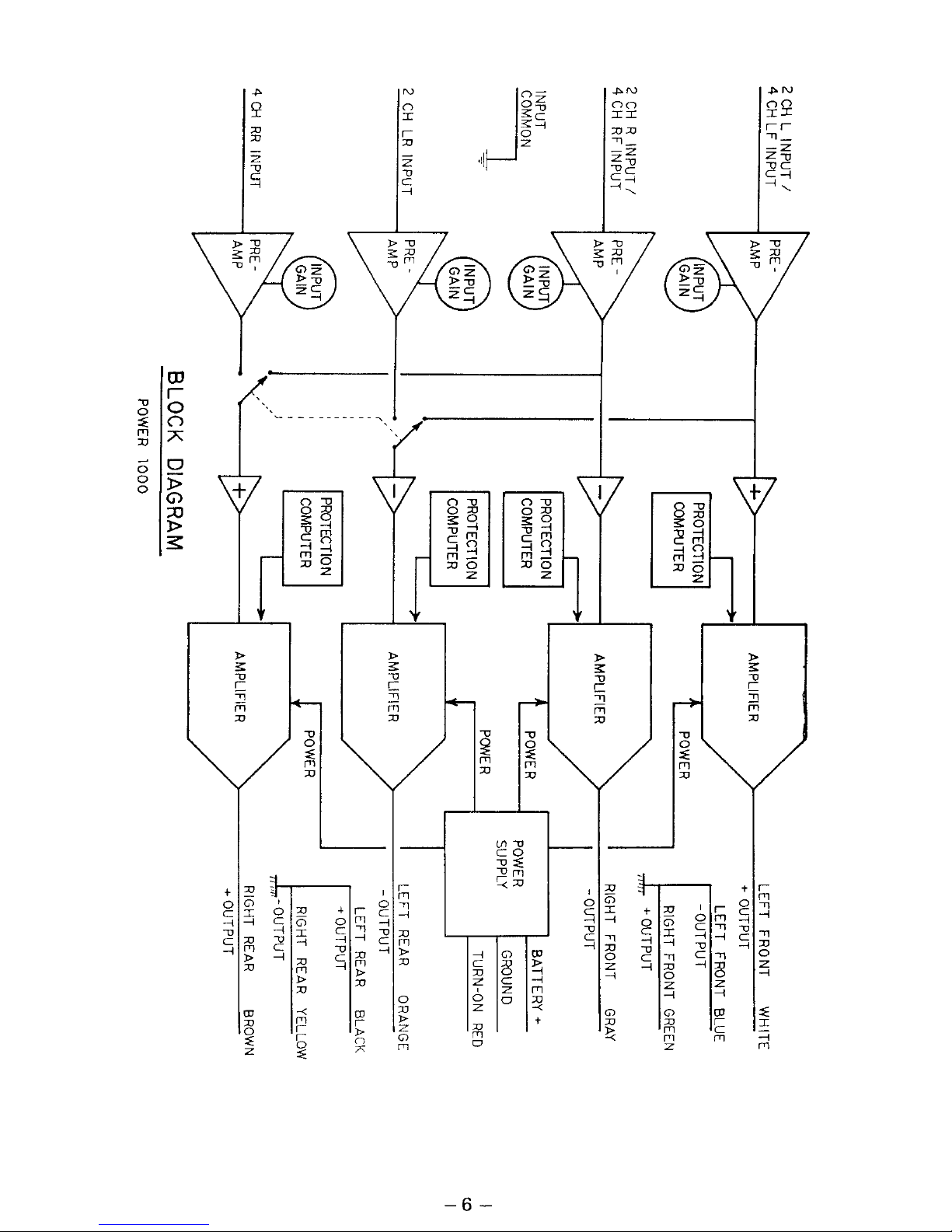
BLOCK DIAGRAM
.................................. Page 6
TURN ON CONNECTION
............................ Page 7
SPEAKER CONNECTIONS
.......................... Page 7
SPEAKER WIRE ....................................
Page 8
SPEAKER IMPEDANCE
.............................
Page 8
SPEAKER FUSING
.................................
Page 8
PASSIVE CROSSOVER IMPEDANCE ................
Page 9
6 dB/OCTAVE CROSSOVER VALUES ..............
Page 10
12 dB/OCTAVE CROSSOVER VALUES
.............
Page 11
SPEAKER POWER RATINGS
.......................
Page 12
PIEZOELECTRIC TWEETERS ......................
Page 12
BATTERY AND CHARGING SYSTEM ............... Page 13
CROSSOVER SETTINGS
.......................... Page 13
POWER 1000 MOSFET SPECIFICATIONS
..........
Page 14
WARRANTY .......................................
Page 15
BIAMPLIFIED MODE DIAGRAM
.................... Page 17
BIAMPLIFIED STEREO DIAGRAM
.................. Page 18
BIAMPLIFIED STEREO BRIDGED
MONO WOOFER DIAGRAM ....................
Page
19
DUAL STEREO DIAGRAM
.........................
Page 20
BRIDGED STEREO DIAGRAM .....................
Page 21
BRIDGED MONO BIAMPLIFIED DIAGRAM .........
Page 22

-WARNING-
Continuous exposure to sound pressure levels over 110 dB may
cause permanent hearing loss. High-powered autosound
systems may produce sound pressure levels well over 130 dB.
Use common sense as you enjoy your system, and preserve
your hearing.
INTRODUCTION
The Rockford Power 1000 MOSFET is an automotive stereo
power amplifier which will provide state-of-the-art sound in
cars, vans, boats, or wherever a 9 to 16 Volt battery is available.
The Power 1000 MOSFET adjustable input circuits are designed
to match almost any music source, from low preamp levels to
speaker levels, with negligible noise. The amplifiers will drive all
normal speaker types, impedances, and configurations.
Internal protection circuitry in the Power 1000 MOSFET
amplifier prevents damage due to shorts, system power
problems, or
internal failures. The Power 1000 MOSFET
incorporates internal battery line filtering and extensive noise
prevention circuitry.
The Power 1000 MOSFET amplifier should be PROFESSIONALLY
INSTALLED. The length and nature of your warranty are
dramatically affected if you attempt to install it yourself (see
Warranty).
This is because professional installers are experienced with
making your car sound right the first time. They make their
installation durable because they don’t want continuing problems
and complaints
-
their reputations are valuable.
-1-

SYSTEM FLEXIBILITY
Four bridgeable channels in the Power 1000 MOSFET provide
unmatched system flexibility with simple wiring changes. Some
of the possibilities are:
Biamplified Stereo
-
A pair of channels drives mid- and highfrequency speakers; another pair drives the woofers, The
external crossover (XV-l) is set to separate the input
frequencies into high and low frequencies for each speaker
system.
Biamplified Stereo with Bridged Mono Woofer
-
Otherwise
similar to the Biamplified Stereo system above, this arrange-
ment bridges the two low channels into a single woofer.
Bridged Stereo
-
Each pair of channels on the Left and Right
sides is bridged into a full-range speaker system.
Bridged Mono Biamplified
-
This configuration produces full
power into one mono channel. The front channel pair is
bridged into a mid-tweeter speaker system and the rear
channel pair is bridged into a woofer. The external crossover
(XV-l) is set to separate woofer and midrange frequencies.
Dual Stereo
-
The power amp acts as two separate stereo
amplifiers, one channel pair for rear full range speakers, one
for front full range speakers. If only one set of speakers can
handle bass frequencies, an external high crossover (XV-l)
can be set to cut off the front speakers’ low frequency drive.
Stereo Woofer Amp
-
Similar to Bridged Stereo except that the
inputs are driven by an external crossover (XV-l) with the high
frequency drive going to a different amp.
All of these system configurations are obtained with simple
wiring variations; there are no special “black boxes” to buy and
the system may be modified at any time.
AMPLIFIER BRIDGING
Operating an amplifier in the “bridged” or “strapped mono”
mode means driving one speaker or speaker system with two
amplifier channels. Each channel will put out full power into its
half of the speaker load, so the system can drive the speaker with
double the power that a single amplifier channel would be
capable of.
-2-

When amplifiers are bridged into a single speaker, each amplifier
“sees” half the total speaker impedance.
Rockford-Fosgate amplifiers are designed so that connecting
the amplifier for bridged mode is a simple matter of using the
correct speaker leads as shown in the appropriate system
diagram. In theseamplifiers, one channel of each pair is inverted
in the amplifier. In normal stereo use, the inverted channel
output isconnected to the negative lead of its speaker load, thus
preserving the system’s polarity. In the bridged mode, the
inverted channel is connected to the negative lead of the
speaker to be bridged, and the positive lead is connected to the
non-inverted channel. This provides the out-of-phase drives
required for bridged operation.
The Power 1000 MOSFET is designed so that the four amplifier
sections can be bridged in several ways. Right and Left High-
Frequency channels can be bridged. The Right Low and Left
Low-Frequency channels can be bridged, the Right High and
Right Low channels can be bridged together, and the Left Low
and Left High channels can be bridged. These combinations
allow an unmatched flexibility in designing stereo, biamplified,
and hybrid bridged systems.
The Power 1000 MOSFET amplifier can deliver 500 Watts into a
bridged 4-Ohm speaker. This is enough power to destroy almost
any speaker made. Be sure to use fuses.
INPUT CONNECTIONS (RCA PIN JACKS)
Theamplifier’ssignal inputfemalepin jacksshould beconnected
to the source unit’s signal outputs.
If the source unit has “RCA” pin jack outputs, connect the Power
1000 MOSFET to the source with a standard male to male “RCA”
cable. In some cases, system noise rejection will be improved by
using high-quality braided-shield or double-shielded interconnecting cables.
When the source unit does not have pin jack outputs, get an
appropriate adapter from your dealer, or use Rockford adapter
cable No. AS-524.
Some higher-powered source units employ “bridged” output
circuits (“BTL”outputs). Units with bridged outputsare normally
rated at 15 to 25 Watts output by the manufacturer. To connect
-3-

this type of unit to a Power 1000 MOSFET amplifier, the speaker
positive (+) wires should go to the adapter cable center
conductors, but the cable shield ground must be connected to
the source chassis, NOT the speaker negative (-) wires.
Be sure to route the Power 1000 MOSFET signal input cable
away from the Orange power wire and the car’s wiring harnesses,
to avoid noise coupling.
Pre-assembled interconnector adapters are available from
Rockford Corporation for a wide variety of source units.
NOTE: In most Pioneer pre-amp output units, and some others,
the audio shield ground is not at the source chassis common.
For these units, connect the shield lines to both the audio shield
and the chassis common.
INPUT LEVEL CONTROLS
The Power 1000 MOSFET input level controls are accessible
with a jeweler’s screwdriver through four holes in the cover. The
controls are factory-preset to a level which matches most 500
millivolt to 1 Volt rated preamp-output source units.
If you are using the amp in bridged stereo or 2-channel mode
adjust only the controls labeled 2-channel/4-channel front. If
you are using a fader or crossover before the amplifier then
adjust all four channels.
If you are using the speaker-output leads of the source unit, turn
the Power 1000 MOSFET input controls fully counterclockwise
to their minimum gain position.
If the volume control of the source is “touchy” and/or noisy
that is, if just a little volume from the source drives the amplifier
into distortion-reduce the Power 1000 MOSFET input gain
controls so that the distortion doesn’t start until the source
volume is at about 3/4 of its rotation.
If maximum volume from the source won’t drive the Power 1000
MOSFET into distortion, increase the Power 1000 MOSFET
input gain controls until distortion starts at about 3/4 volume.
POWER CONNECTION (ORANGE 4-GAUGE WIRE)
The Orange wire must be connected directly to the positive
terminal of the battery to provide a power source with a low
-4
-

voltage drop and low noise. If the power is connected to any
other point (the fuse block, for instance) the amplifier’s power
output will be reduced and oscillations and noise may distort the
sound. If the power wire must be extended, use only 6-gauge or
larger wire and make a good splice.
It is best to use as short a wire run as possible. DO NOT run the
power wire next to the input cabling to the amplifier; it wil induce
noise.
Avoid running the Orange power wire near the radio’s antenna
or power leads, or near sensitive equipment or harnesses. The
Orange power wire carries substantial currents and could
induce noise.
The Orange wire is provided with an in-line 100 ampere fuse. Do
not use a larger fuse or the amplifier will not be adequately
protected, and you risk damage to your car’s electrical system.
GROUND CONNECTION (BLACK 6-GAUGE WIRES)
The ground wires must be connected directly to the car chassis,
near the amplifier. Connect the ground wires to separate spots
on the chassis at least one foot apart. Ground loops are
aggravated by the length of the ground wire orany resistance in
the ground path. For this reason we don’t recommend extending
the ground wires in any installation.
The ground points in the car should be pieces of chassis metal
that are welded to the main body of the car. Painted surfaces
should be scraped or sanded clean before the ground lugs are
bolted down. (Cover the bare-metal areas with paint or grease to
prevent rust.) A dab of Panduit CMP-200-1 between the lugs and
the chassis will improve grounding performance.
INPUT MODE SWITCH
The input of the Power 1000 MOSFET normally comes from the
2-channel/4-channel front RCA connectors. However, there are
some cases where it is desirable to be able to drive the rear
channels independently. For instance, if one wanted to drive the
system as two completely independent stereo amplifiers, one
would need to drive the front channel with one stereo pair, and
the rear channel with another.
 Loading...