

Rockford Fosgate Fanatic P FNP2401x, Fanatic X FNX2401, Fanatic Q FNQ2401x, Fanatic P FNP2401, Fanatic Q FNQ2401 Operation & Installation
Page 1

® ®
car audio
fanatics
for
Operation
& Installation
FNP2401x
FNX2401x
FNQ2401x
Page 2

Dear Customer,
Congratulations on your purchase of the world's finest brand of car audio speakers. At
Rockford Fosgate we are fanatics about musical reproduction at its best, and we are
pleased you chose our product. Through years of engineering expertise, hand craftsmanship and critical testing procedures, we have created a wide range of products that
reproduce music with all the clarity and richness you deserve.
For maximum performance we recommend you have your new Rockford Fosgate
product installed by an Authorized Rockford Fosgate Dealer, as we provide specialized
training through Rockford Technical Training Institute (RTTI). Please read your
warranty and retain your receipt and original carton for possible future use.
Great product and competent installations are only a piece of the puzzle when it comes
to your system. Make sure that your installer is using 100% authentic installation
accessories from Connecting Punch in your installation. Connecting Punch has
everything from RCA cables and speaker wire to Power line and battery connectors.
Insist on it! After all, your new system deserves nothing but the best.
To add the finishing touch to your new Rockford Fosgate image order your Rockford
wearables, which include everything from T-shirts and jackets to hats and sunglasses.
To get a free brochure on Rockford Fosgate products and Rockford accessories, in the
U.S. call 480-967-3565 or FAX 480-967-8132. For all other countries, call +001-480967-3565 or FAX +001-480-967-8132.
If, after reading your manual, you still have questions regarding this product,
we recommend that you see your Rockford Fosgate dealer. If you need further
assistance, you can call us direct at 1-800-669-9899. Be sure to have your serial
number, model number and date of purchase available when you call.
PRACTICE SAFE SOUND™
CONTINUOUS EXPOSURE TO SOUND PRESSURE LEVELS OVER 100dB
MAY
CAUSE PERMANENT HEARING LOSS. HIGH POWERED AUTOSOUND
SYSTEMS
MAY PRODUCE SOUND PRESSURE LEVELS WELL OVER
130dB. USE COMMON SENSE AND PRACTICE SAFE SOUND.
The serial number can be found on the outside of the box. Please record it in
the space provided below as your permanent record. This will serve as
verification of your factory warranty and may become useful in recovering your
product if it is ever stolen.
Serial Number: ________________________________
Model Number:________________________________
Page 3

Welcome to Rockford Fosgate! This manual is designed to provide information
for the owner, salesperson and installer. For those of you who want quick
information on how to install this product, please turn to the
Installation
Section
of this manual or refer to the icons listed below. Other information can
be located by using the Table of Contents. We, at Rockford Fosgate, have
worked very hard to make sure all the information in this manual is current. But,
as we are constantly finding new ways to improve our product, this information
is subject to change without notice.
G
ETTING
S
TARTED
Sections marked
TROUBLESHOOTING
include recommendations for
curing
installation problems
I
N
S
T
A
L
L
A
T
I
O
N
® ®
TROUBLE-
S
H
O
O
T
I
N
G
T
ABLE OF
C
ONTENTS
Introduction................................................................................................1
Package Contents ....................................................................................... 1
Installation Considerations ...........................................................................2
Mounting Location ...................................................................................... 3
Installation ................................................................................................. 4
Troubleshooting.......................................................................................... 6
Specifications ............................................................................................. 7
Warranty Information ..................................................................................9
International Information............................................................................ 10
Sections marked
INSTALLATION
include “slam dunk”
wiring connections
Page 4

I
NTRODUCTION
This manual provides information on the features and installation of the
Fanatic P, X, & Q Tweeter Systems. We suggest you save this manual for
future reference.
We strongly recommend you have your Authorized Rockford Fosgate Dealer
install the Fanatic P, X, or Q Tweeter System. If you do choose to install the
system yourself, please be sure to read the entire manual before beginning.
FNP2401x
(2) FNP2401 Tweeters
Includes 3/4" [20mm] mylar dome tweeter, flush mount housing,
surface mount housing, wedge mount housing
(2) Tweeter Mounting Brackets
(4) #6 x .500 Screws
(8) #8 x .75 Phillips Screws
(2) .110 Female Fast-on Connectors
(2) .110 Male Fast-on Connectors
(2) FNP241x High-Pass Crossovers
(12')24 gauge Speaker Wire
P
ACKAGE
C
ONTENTS
– 1 –
FNX2401x
(2) FNX2401 Tweeters
Includes 3/4" [20mm] silk dome tweeter, flush mount housing,
surface mount housing, wedge mount housing
(2) Tweeter Mounting Brackets
(4) #6 x .500 Screws
(8) #8 x .75 Phillips Screws
(2) .110 Female Fast-on Connectors
(2) .110 Male Fast-on Connectors
(2) FNX241x High-Pass Crossovers
(12')24 gauge Speaker Wire
FNQ2401x
(2) FNQ2401 Tweeters
Includes 3/4" [20mm] aluminum dome tweeter, flush mount housing,
surface mount housing, wedge mount housing
(2) Tweeter Mounting Brackets
(4) #6 x .500 Screws
(8) #8 x .75 Phillips Screws
(2) .110 Female Fast-on Connectors
(2) .110 Male Fast-on Connectors
(2) FNQ241x High-Pass Crossovers
(12')24 gauge Speaker Wire
Page 5

I
NSTALLATION
C
ONSIDERATIONS
Tools Needed
The following is a list of some of the tools necessary for the installation of your
speakers.
Power Drill with assorted bits #2 Phillips Screwdriver
Tape Measure Voltmeter
General
1. For safety, disconnect the negative lead from the battery prior to beginning
the installation.
2. Never run wires underneath the vehicle. Running the wires inside the vehicle
provides the best protection.
3. Avoid running wires over or through sharp edges. Use rubber or plastic
grommets to protect any wires routed through metal.
4. Mount the speakers/crossovers away from electrical sources (other than the
amplifier), i.e., power cables, electronic fuel pumps, vehicle computers,
and other potential noise sources.
5. Mount the speakers/crossovers away from areas of extreme heat or
moisture.
Tweeters
1. When mounting the tweeter(s) in the door of a vehicle, make sure they do
not interfere with either the door or window operation.
2. Please refer to the Specifications section of this manual for proper
mounting diameter and depth of the tweeters.
Crossovers
1. Make sure there is a flat area large enough for the crossover to mount.
2. For best results, mount the crossover(s) next to the amplifier for a decorative
finish to the installation and to provide an easy upgrade (no new wires to
run) for a bi-amp Rockford Fosgate system in the future.
– 2 –
Page 6
• Sound radiated from a “point source” has the most optimum stereo imaging
because the separation of the acoustical centers between the midrange and
tweeter for each channel is at the optimum. Figure 2-A describes a
horizontal speaker alignment. In a closed environment such as an
automobile, horizontal speaker alignment can cause severe amplitude and
phase differences which will degrade not only the imaging, but also the
frequency response. This is due to the path length differences between the
M
OUNTING
L
OCATION
A solid front stage with a good image is one of the most difficult tasks to achieve
in a vehicle. No car has the optimum listening environment. This makes proper
sound staging very difficult to accomplish. Most speakers tend to be placed
where they will fit easily, as opposed to where they can perform the best.
The
mounting location of your speakers will have a great effect on the sound quality
of your stereo system. The special care taken to place the speakers will yield
many hours of listening enjoyment in return. Several important recommendations should be followed.
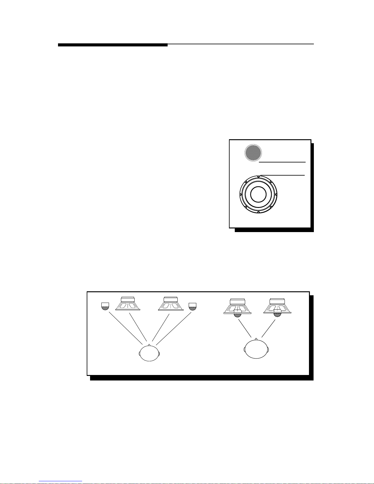
• Place the speakers where they have a direct
path to the listening area.
• For the best integration between the midrange
and tweeter, the tweeter should be placed
less than 2" from the midrange. (Figure 1)
• If you cannot place the tweeter less than 2"
from the midrange, then place the tweeter
more than 7" from the midrange. Placing
the tweeter 2"-7" from the midrange can
cause destructive interference (frequency
response problems) which will affect the
speaker's ability to reproduce the frequency range around the crossover
frequency of the system.
• Whenever possible, place the tweeter directly above or below the midrange
as this maximizes the imaging (point source) capability of the speakers.
(Figure 2)
Figure 1
2" or less
Figure 2-A
Figure 2-B
– 3 –
Page 7
– 4 –
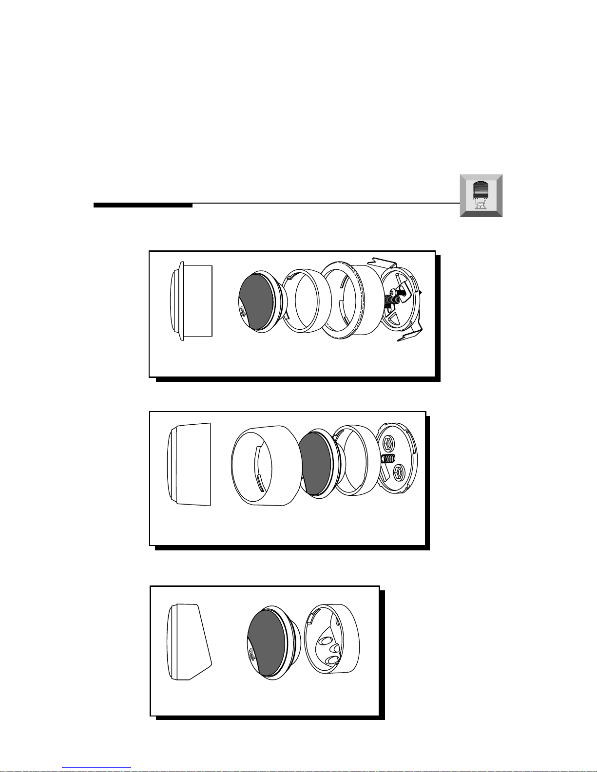
Flush Mount Tweeter
Tweeter
Trim
Ring
Back
Plate
Flush
Housing
Surface Mount Tweeter
Tweeter Trim
Ring
Back
Plate
Surface
Housing
midrange and tweeter. Figure 2-B displays a vertical alignment between
the midrange and tweeter. With a vertical alignment, the path length
difference between the midrange and tweeter are reduced to a minimum.
The result is a negligible difference in path lengths between the midrange
and tweeter regardless of the proximity of the listener to the speakers.
Mounting the speaker with minimum path length difference will ensure the
best staging and imaging possible from your audio system.
Wedge Mount Tweeter
Tweeter
Wedge
Housing
I
NSTALLATION
I
N
S
T
A
L
L
A
T
I
O
N
® ®
Page 8

fanatic P Crossover Connections
• Be Sure to Maintain Speaker Polarity
– 5 –
• Be sure to maintain speaker polarity
• 0dB tweeter level matches the
amplitude of the tweeter to the
midrange
• –3dB tweeter level reduces the
amplitude –3dB lower than the
midrange (ideal for tweeters located
high in door panel and midranges
located low in kick panel)
• Replaceable Tweeter Protection Bulb
The light bulb acts as a fuse to protect
against overload. If the bulb burns out,
remove the burned out bulb and insert
a new bulb (part# HDW10932) into
the retainer clips.
fanatic X Crossover Connections
• Be sure to maintain speaker polarity
• 0dB tweeter level matches the amplitude
of the tweeter to the midrange
• –3dB/–6dB tweeter level reduces the
amplitude –3dB or –6dB lower than the
midrange (ideal for tweeters located high
in door panel and midranges located low
in the kick panel)
• 0°/180° tweeter phase matches the
phase response of the tweeter to the
midrange. Leave the switch in the
position that results in the best sound
quality.
• Replaceable Tweeter Protection Bulb
The light bulb acts as a fuse to protect
against overload. If the bulb burns out,
remove the burned out bulb and insert a
new bulb (part# HDW10932) into the
retainer clips.
fanatic Q Crossover Connections
-3db Tweeter Level
0db Tweeter Level
-6db Tweeter Level
0° 180°
INPUT TWEETER
- +- +
(One channel of
amplifier)
–
+
+
–
Negative (Black Wire)
Positive (Black/White Stripe Wire)
Tweeter Negative
Tweeter Positive +
(One channel of amplifier)
–
+
–
+
–
(One channel of
amplifier)
INPUT TWEETER
- +- +
-3db Tweeter Level
0db Tweeter Level
+
–
Page 9

T
ROUBLESHOOTING
No sound from
speakers
Symptom Diagnosis Remedy
Check and repair or replace
wiring as needed.
Check system with known
working amplifier and repair
or replace as needed.
Check for shorts in the wiring
with a volt/ohm meter and repair or replace wires as needed.
Check system with known working speaker and repair or replace as needed.
Wires between amplifier,
crossover or speakers not
connected properly.
Amplifier has no output.
Speaker wires are shorted
to each other or to the chassis of the vehicle.
Speakers are blown.
Incorrect wiring between
crossover and speakers
Excessive power from amplifier
Equalizer in system (if
available) has excessive
boost in the high frequency
range
Check wiring and repair or replace as needed.
Check gain settings on amplifier and readjust as necessary
Check settings on equalizer and
readjust as necessary
Distorted sound
from speakers
Tweeters “burn
up” easily
– 6 –
Engine noise from
one or more
speakers
Check for shorts in the wiring
with a volt/ohm meter and repair or replace wires as needed.
Re-route speaker wiring away
from noise sources. (Refer to
the Installation Consider-
ations section of this manual.)
Move crossovers away from
noise sources. (Refer to the In-
stallation Considerations section of this manual.)
Speaker wires shorted to
chassis of vehicle.
Speaker wires are routed
near radiated noise source.
(Power cables, vehicle
computers, etc.)
Crossover is mounted near
radiated noise source.
(Power cables, vehicle
computers, etc.)
TROUBLE-
S
H
O
O
T
I
N
G
Page 10

Tweeter System Model Number FNP2401x FNX2401x FNQ2401x
Tweeter Model Number FNP2401 FNX2401 FNQ2401
Dome Type Mylar Silk Aluminum
Nominal Diameter
3
⁄4" (20mm)
3
⁄4" (20mm)
3
⁄4" (20mm)
Nominal Impedance 4Ω 4Ω 4Ω
Frequency Response 2.8kHz-20kHz 1.8kHz-20kHz 1.9kHz-20kHz
Sensitivity 91dB 93dB 91dB
RMS Power Handling 50 Watts* 70 Watts* 100 Watts*
Mounting Diameter See drawings See drawings See drawings
Mounting Depth See drawings See drawings See drawings
Crossover Model Number FNP241x FNX241x FNQ241x
Crossover Type High-Pass High-Pass High-Pass
Crossover Frequency 6.3kHz@4Ω 4.0kHz@4Ω 4.0kHz@4Ω
Crossover Slope 18dB/octave HP 18dB/octave HP 24dB/octave HP
Filter Q 0.707 Butterworth 0.707 Butterworth 0.707 Butterworth
Tweeter Protection Optical Protection Optical Protection Optical Protection
Tweeter Pad N/A 0dB/–3dB 0dB/–3dB/–6dB
Tweeter Phase N/A N/A 0° / 180°
Dimensions See drawings See drawings See drawings
S
PECIFICATIONS
(Specifications are subject to change without notice)
– 7 –
* Power Ratings (PE) is established with recommended filter network.
Wedge
Mount
Surface
Mount
Flush
Mount
1.75"
.875"
3.687"
4.437"
1.74"
1.00"
1.94"
.375"
1.00"
.25"
1.795"
.965"
.675"
1.562"
1.24"
FNP2401x
Page 11

– 8 –
Wedge
Mount
Surface
Mount
Flush
Mount
1.74"
1.00"
1.94"
.375"
1.00"
.25"
1.795"
.965"
.675"
1.562"
1.24"
Wedge
Mount
Surface
Mount
Flush
Mount
1.74"
1.00"
1.94"
1.00"
.25"
1.795"
.965"
.675"
1.562"
1.24"
L = 3.517”
L = 2.547”
H = 1.135”
INPUT TWEETER
- +- +
L = 4.519”
L = 3.248”
H = 1.465”
INPUT TWEETER
- +- +
.375"
FNX2401x
FNQ2401x
Page 12

– 9 –
L
IMITED
W
ARRANTY
I
NFORMATION
Rockford Corporation offers a limited warranty on Rockford Fosgate products on the following
terms:
• Length of Warranty
1 year on speakers 30 days on speaker B-stock (receipt required)
3 years on electronics 90 days on electronic B-stock (receipt required)
2 years on source units
• What is Covered
This warranty applies only to Rockford Fosgate products sold to consumers by Authorized
Rockford Fosgate Dealers in the United States of America or its possessions. Product
purchased by consumers from an Authorized Rockford Fosgate Dealer in another country
are covered only by that country’s Distributor and not by Rockford Corporation.
• Who is Covered
This warranty covers only the original purchaser of Rockford product purchased from an
Authorized Rockford Fosgate Dealer in the United States. In order to receive service, the
purchaser must provide Rockford with a copy of the receipt stating the customer name,
dealer name, product purchased and date of purchase.
• Products found to be defective during the warranty period will be repaired or replaced
(with a product deemed to be equivalent) at Rockford's discretion.
• What is Not Covered
1. Damage caused by accident, abuse, improper operations, water, theft
2. Any cost or expense related to the removal or reinstallation of product
3. Service performed by anyone other than Rockford or an Authorized Rockford Fosgate
Service Center
4. Any product which has had the serial number defaced, altered, or removed
5. Subsequent damage to other components
6. Any product purchased outside the U.S.
7. Any product not purchased from an Authorized Rockford Fosgate Dealer
• Limit on Implied Warranties
Any implied warranties including warranties of fitness for use and merchantability are
limited in duration to the period of the express warranty set forth above. Some states do not
allow limitations on the length of an implied warranty, so this limitation may not apply. No
person is authorized to assume for Rockford Fosgate any other liability in connection with
the sale of the product.
• How to Obtain Service
Please call 1-800-669-9899 for Rockford Customer Service. You must obtain an RA#
(Return Authorization number) to return any product to Rockford Fosgate. You are
responsible for shipment of product to Rockford.
Ship to: Electronics
Rockford Corporation
Warranty Repair Department
2055 E. 5th Street
Tempe, AZ 85281
RA#:_________________
Ship to: Speakers
Rockford Acoustic Design
(Receiving-speakers)
609 Myrtle N.W.
Grand Rapids, MI 49504
RA#:_________________
Page 13

INTERNATIONAL
I
NFORMATION
– 10 –
Page 14

Conexiones del Crossover – fanatic P
• Asegúrese de mantener la polaridad de los parlantes
– 11 –
LEA DETENIDAMENTE LAS SIGUIENTES INSTRUCCIONES DE INSTALACIÓN DEL
PRODUCTO.
I
NTRODUCCIÓN
Este manual contiene información sobre la construcción, installación y
funcionamiento de los Fanatic P, X y Q tweeters. Le recomendamos que conserve
el manual para futuras consultas.
Es preferible que la instalación de los tweeters Fanatic P, X y Q sea realizada por
un distribuidor autorizado Rockford Fosgate. Si prefiere realizar la instalación
usted mismo, asegurese de leer el manual en su totalidad antes de comenzar.
M
ONTAJE
• Le mejor interacción entre tweeter y medio
se consigue si no están separados entre si
más de 5 cenimetros. (Figura 1)
no superior a 5cm
Figura 1
–
+
–
Negativo (cable Negro)
Positivo (cable Negro
con raya Blanca)
Negativo Tweeter
Positivo de Agudo +
(Un canal del
amplificador)
I
N S TALACIÓN
I
N
S
T
A
L
L
A
T
I
O
N
® ®
Page 15

– 12 –
E
SPAÑOL
• Asegúrese de mantener la polaridad de
los parlantes
• Nivel de 0dB del Agudo cuadra con la
amplitud del Agudo al Mediorango
• Nivel de –3dB del Agudo reduce la
amplitud del Agudo –3dB más bajo que el
mediorango.(Ej. Ideal para agudos
colocados en paneles de puerta elevados
y mediorangos localizados en paneles
bajos – kick panel)
• Bombilla recambiable de protección del
altavoz de alta frecuencia La bombilla
de luz actúa como un fusible para
proteger contra sobrecargas. Si la
bombilla se quema, saque la bombilla
quemada e inserte una bombilla nueva
(pieza Nº HDW10932) en las grapas de
sujeción.
Conexiones del Crossover – fanatic X
• Asegúrese de mantener la polaridad de
los parlantes
• Nivel de 0dB del Agudo cuadra con la
amplitud del Agudo al Mediorango
• Nivel del Agudo –3dB/–6dB reduce la
Amplitud del agudo –3dB ó –6dB más
bajo que el mediorango. (Ej. Ideal para
agudos colocados en paneles de puerta
elevados y mediorangos localizados en
paneles bajos – kick panel)
• Fase del Agudo 0/180° ajusta la
respuesta de fase del agudo al
mediorango (eminente cuando el agudo
está colocado lejos del mediorange). Deje
el conmutador en la posición que resulte
con la mejor calidad de sonido.
• Bombilla recambiable de protección del
altavoz de alta frecuencia La bombilla
de luz actúa como un fusible para proteger
contra sobrecargas. Si la bombilla se
quema, saque la bombilla quemada e
inserte una bombilla nueva (pieza Nº
HDW10932) en las grapas de sujeción.
Conexiones del Crossover – fanatic Q
+
–
INPUT TWEETER
- +- +
Nivel de –3dB
del Agudo
Nivel de 0dB
del Agudo
(Un canal del
amplificador)
+
–
INPUT TWEETER
- +- +
–
+
+
–
Nivel de –3dB del Agudo
Nivel de 0dB del Agudo
(Un canal del amplificador)
Nivel de –6dB del Agudo
0° 180°
I
N S TALACIÓN
I
N
S
T
A
L
L
A
T
I
O
N
® ®
Page 16

Connexion du filtre – fanatic P
• Vérifier les polaritées des haut-parleurs
– 13 –
Veuillez lire les instructions suivantes pour l'installation de ces produits.
I
NTRODUCTION
Ce manuel contient des informations sur les caractéristiques et l'installation des
médium et l'aigu Fanatic P, X et Q. Nous vous proposons de garder ce manuel
pour toute référence future.
Nous vous recommandons vivement de faire installer votre des médium et l'aigu
Fanatic P, X et Q par un dealer agréé Rockford Fosgate. Si vous choisissez
d'installer le système vous même, assurez-vous de lire ce manuel entièrement
avant de commencer.
• Pour bénéficier d'une harmonie maximum
entre le médium et l'aigu l'éloignement entre
ces deux haut-parleurs devrait être de moins
de 5 cm entre les 2 chassis. (Figure 1)
moins de 5cm
Figure 1
E
MPLACEMENT DE
M
ONTAGE
I
NSTALLATION
–
+
–
Négatif (câble noire)
Positif (câble noire rayé
de blanc)
Négatif de l’aigu
Positif de l’aigu +
(Un canal de
l’amplificateur)
I
N
S
T
A
L
L
A
T
I
O
N
® ®
Page 17

– 14 –
F
RANÇAIS
• Vérifier les polaritées des haut-
parleurs
• 0dB Pas d'atténuation de l'aigu par
rapport au médium.
• –3dB d'atténuation du niveau de
l'aigu
–3dB d'atténuation par rapport au
médium. (Ex: Idéal pour le
positionnement de l'aigu en haut de
portière et le mèdium en bas ou “kick
panel” Volume de charge créer en bas
de porte ou dans l'angle de celle-ci,
au niveau des pieds.)
• Ampoule de protection remplaçable
pour tweeter Cette ampoule sert de
fusible de protection contre les
surcharges. Si lampoule brûle,
retirez-la et placez-en une neuve (réf.
#HDW10932) dans les clips de
retenue.
Connexion du filtre – fanatic X
• Vérifier les polaritées des haut-
parleurs
• 0dB Pas d'atténuation de l'aigu par
rapport au médium.
• –3 ou –6dB d'atténuation de l'aigu
–3 ou –6dB de réduction du niveau par
rapport au médium. (Ex: Idéal pour le
positionnement de l'aigu en haut de
portière et le mèdium en bas ou “kick
panel” Volume de charge créer en bas
de porte ou dans l'angle de celle-ci, au
niveau des pieds.)
• 0°/180° Inversion de phase de l'aigu
par rapport au médium. Cette disposition
en phase relative est utile quand l'aigu
est positionner loin du médium.
L'inversion du commutateur de phase
• Ampoule de protection remplaçable
pour tweeter Cette ampoule sert de
fusible de protection contre les
surcharges. Si lampoule brûle, retirez-la
et placez-en une neuve (réf.
#HDW10932) dans les clips de retenue.
apportera une modification significative
de l'écoute.
Connexion du filtre – fanatic Q
+
–
INPUT TWEETER
- +- +
Niveau de l’aigu –3dB
Niveau de l’aigu 0dB
(Un canal de
l’amplificateur)
+
–
INPUT TWEETER
- +- +
–
+
+
–
Niveau de l’aigu –3dB
Niveau de l’aigu 0dB
(Un canal de l’amplificateur)
Niveau de l’aigu –6dB
0° 180°
I
NSTALLATION
I
N
S
T
A
L
L
A
T
I
O
N
® ®
Page 18

Frequenzweichen Anschlüsse – fanatic P
• Achten Sie auf die Lautsprecherpolarität
Die folgende Bedienungsanleitung soll Ihnen beim Einbau eine Hilfestellung
geben.
E
NLEITUNG
Diese Bedienungsanleitung enthält Informationen für den Gebrauch und Einbau
des Fanatic P, X und Q tweeters. Wir empfehlen, diese auch für Fragen in der
Zukunft sorgfältig aufzubewahren.
Es ist empfehlenswert, sich das Fanatic P, X und Q tweeters von einem
Autorisierten Rockford Fosgate Fachhändler einbauen zu lassen. Sollten Sie den
Einbau jedoch selber vornehmen wollen, so empfehlen wir Ihnen, die
Bedienungsanleitung sorgfälitg zu lesen.
• Für das optimale Zusammenspiel von Mittelund Hochtöner, sollte der Hochtöner niemals
weiter als 5cm vorn Mitteltöner entfernt
montiert werden. (Abb. 1)
Abstand max. 5cm
(Abb. 1)
E
INBAUORT
– 15 –
E
INBAU
I
N
S
T
A
L
L
A
T
I
O
N
® ®
–
+
–
Minus (Schwarzes Kabel))
Plus (Schwarz/Weiβ
gestreiftes Kabel)
Hochtöner Minus
Hochtöner Plus +
(Ein Kanal des
Verstärkers)
Page 19

– 16 –
D
EUTSCH
• Achten Sie auf die Lautsprecherpolarität
• 0dB Hochtonabsenkung stimmt mit der
Lautstärke med mitteltöners überein
• –3dB Hochtonabsenkung, reduziert die
Lautstärke des Hochtöners gegenüber der
Lautstärke des Mitteltöners
–3dB leiser, als der Mitteltöner (Ideal für
Einbauten, bei denen die Hochtöner im
Armaturenbrett und die Mitteltöner in
Fuβraum eingesetzt werden)
• Austauschbare Birne zum Schutz des
Hochtöners Die Glühbirne dient als
Sicherung, um vor Überladung zu
schützen. Sollte die Birne ausbrennen, die
ausgebrannte Birne entfernen und eine
neue Birne (Ersatzteilnr. HDW10932) in
den Halterungsclip einführen.
Frequenzweichen Anschlüsse – fanatic X
• Achten Sie auf die Lautsprecherpolarität
• 0dB Hochtonabsenkung stimmt mit der
Lautstärke med mitteltöners überein
• –3dB/–6dB Hochtonabsenkung, reduziert
die Lautstärke des Hochtöners um –3dB
lder – 6dB gegenüber der Lautstärke
Mitteltöners (Ideal für Einbauten, bei denen
die Hochtöner im Armaturenbrett und die
Mitteltöner in Fuβraum eingesetzt werden)
• 0°/180° Phasenkorrektur, ändert die
Phase (Ideal, wenn der Hochtöner weit
entfernt vom Mitteltöner eingebaut wird).
Schieben Sie den Schalter in die Position,
bei der sich die beste Soundqualität
einstellt.
• Austauschbare Birne zum Schutz des
Hochtöners Die Glühbirne dient als
Sicherung, um vor Überladung zu schützen.
Sollte die Birne ausbrennen, die
ausgebrannte Birne entfernen und eine neue
Birne (Ersatzteilnr. HDW10932) in den
Halterungsclip einführen.
Frequenzweichen Anschlüsse – fanatic Q
+
–
INPUT TWEETER
- +- +
–3dB
Hochtonabsenkung
0dB
Hochtonabsenkung
(Ein Kanal des
Verstärkers)
+
–
0° 180°
–3dB Hochtonabsenkung
0dB Hochtonabsenkung
(Ein Kanal des Verstärkers)
–6dB Hochtonabsenkung
INPUT TWEETER
- +- +
–
+
+
–
E
INBAU
I
N
S
T
A
L
L
A
T
I
O
N
® ®
Page 20

Connessioni del crossover – fanatic P
• Assicuratevi di mantenere la corretta polarita degli altoparlanti
Leggere le istruzioni seguenti prima dell'installazione del prodotto.
I
NTRODUZIONE
Questo manuale fornisce informazioni sulle caratteristiche e sul installazione dei
tweeters Fanatic P, X e Q. Vi suggeriamo di conservare questo manuale come
riferimento futuro.
Raccomandiamo fortemente che is tweeter sia installato dal vostro rivenditore
Rockford Fosgate. Se scegliete di procedere con l'installazione da soli, leggete
attentamente tutto il manuale prima di proseguire.
• Per ottenere la miglior integrazione tra tweeter
e midrange, vi suggeriamo di posizionare i
due componenti a meno di 5 cm tra loro.
(Figura 1)
meno di 5 cm
Figura 1
P
OSIZIONAMENTO
– 17 –
I
NSTALLAZIONE
I
N
S
T
A
L
L
A
T
I
O
N
® ®
–
+
–
Negativo (cavo nero)
Positivo (cavo nero/bianco)
Negativo Tweeter
Positivo Tweeter +
(Un canale
dell’amplificatore)
Page 21

– 18 –
I
TALIANO
• Assicuratevi di mantenere la
corretta polarita degli altoparlanti
• 0dB di livello del tweeter accoppia
la sensibilita del midrange a quella
del tweeter
• –3dB di livello del tweeter riduce
l'efficienza del tweeter –3dB lmeno
del midrange (es.: ideale per tweeter
posizionati nella parte alta delle
portiere e midrange molto bassi nelle
tasche)
• Lampadina di protezione tweeter La
lampadina funge da fusibile di
protezione contro i sovraccarichi. Se
la lampadina si rompe, toglierla e
inserirne una nuova (codice
n.HDW10932) nei fermi.
Connessioni del crossover – fanatic X
• Assicuratevi di mantenere la corretta
polarita degli altoparlanti
• 0dB di livello del tweeter accoppia la
sensibilita del midrange a quella del
tweeter
• –3dB/–6dB di livello del tweeter per
abbassarne l'efficienza di 3dB o 6dB
rispetto al midrange(es.: ideale per tweeter
posizionati nella parte alta delle portiere e
midrange molto bassi nelle tasche)
• La fase del tweeter a 0/180° ne accoppia
la corretta fase al midrange (tipicamente
quando i due componenti sono lontani tra
loro). Posizionate l'interruttore nella
posizione a cui corrisponde il miglior
suono.
• Lampadina di protezione tweeter La
lampadina funge da fusibile di protezione
contro i sovraccarichi. Se la lampadina si
rompe, toglierla e inserirne una nuova
(codice n.HDW10932) nei fermi.
Connessioni del crossover – fanatic Q
+
–
INPUT TWEETER
- +- +
-3db livello tweeter
-0db livello tweeter
(Un canale
dell’amplificatore)
+
–
0° 180°
-3dB livello tweeter
-6dB livello tweeter
INPUT TWEETER
- +- +
–
+
+
–
(Un canale dell’amplificatore)
0dB livello tweeter
I
NSTALLAZIONE
I
N
S
T
A
L
L
A
T
I
O
N
® ®
Page 22

11/99
LIT10811
Rockford Fosgate
Rockford Corporation
546 South Rockford Drive
Tempe, Arizona 85281 U.S.A.
In U.S.A., (480) 967-3565
In Europe, Fax (49) 8503-934014
In Japan, Fax (81) 559-79-1265
www.rockfordfosgate.com
MADE IN CHINA
This product is designed, developed and assembled in the USA by a dedicated
group of American workers. The majority of the components used in the
construction of this product are produced by American companies. However,
due to the global nature of their manufacturing facilities and the loudspeaker
parts industry in general, some parts may be manufactured in other countries.
 Loading...