

Page 1
INSTALLATION MANUAL FOR
DETECT-A-FINGER
®
DROP PROBE DEVICE
FOR RESISTANCE-TYPE SPOT WELDERS
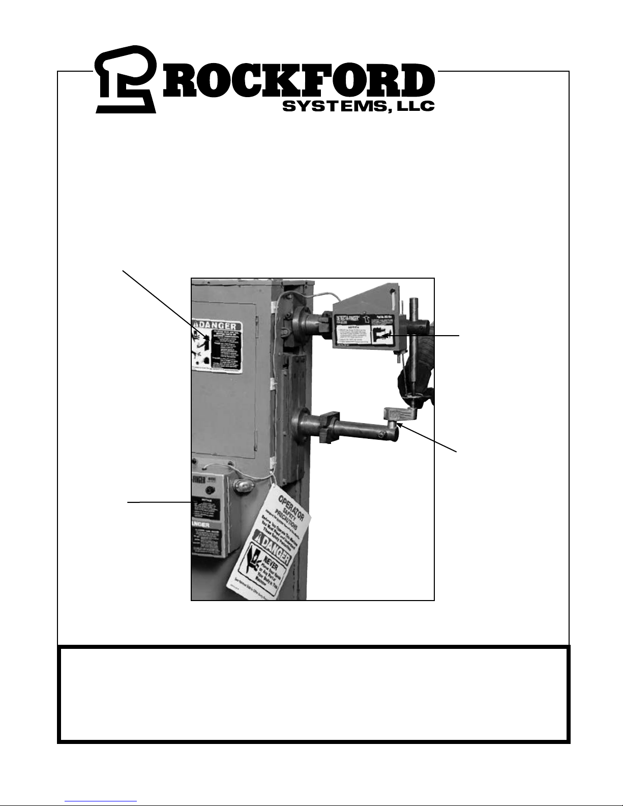
Danger Sign
Sensing Probe
Assembly
Sensing Probe
Control Box
IMPORTANT: PLEASE REVIEW THIS ENTIRE
PUBLICATION BEFORE INSTALLING,
OPERATING OR MAINTAINING THIS DEVICE.
5795 Logistics Parkway • Rockford Systems, LLC, Illinois 61109-2695 • Toll-Free 1-800-922-7533 • Phone 815-874-7891
Fax 815-874-6144 • Web Site www.rockfordsystems.com • E-Mail sales@rockfordsystems.com
Instruction Manual No. KSL-022
Page 2
SECTION 1—IN GENERAL
Detect-A-Finger® Drop Probe Device-Welder
SECTION 1 - IN GENERAL .............................................. 2 - 8
SECTION 2 - INSTALLATION OF COMPONENTS ........ 9 - 16
Control Box ........................................................................ 9
Sensing Probe ............................................................ 10-11
Other Components That May Be Required ................ 12-15
Installation Considerations ............................................... 16
SECTION 3 - OPERATING PROCEDURES &
TROUBLESHOOTING ......................................................... 17-18
SECTION 4 - REPLACEMENT PARTS ............................... 19
SECTION 5 - ORDER FORM & RMA FORM ...................... 20
Safety Precautions
DANGER indicates an imminently hazardous situation which, if not
avoided, will result in death or serious injury.
This safety alert symbol identies important safety messages in
this manual. When you see this symbol, be alert to the possibility of
personal injury, and carefully read the message that follows.
CAUTION
Efcient and safe machine operation depends on the development, implementation and enforcement of a safety
program. This program requires, among other things, the proper selection of point-of-operation guards and safety
devices for each particular job or operation, a thorough safety training program for all machine personnel, that includes
instruction on the proper operation of the machine, the point-of-operation guards and safety devices on the machine,
and a regularly scheduled inspection and maintenance program.
Rules and procedures covering each aspect of your safety program should be developed and published both in an
operator’s safety manual, as well as in prominent places throughout the plant and on each machine. Some rules or
instructions which must be conveyed to your personnel and incorporated into your program include:
CAUTION used without the safety alert symbol indicates a potentially
hazardous situation which, if not avoided, may result in property damage.
Never place your hands or any part of your body in this machine.
Never operate this machine without proper eye, face and body protection.
Never operate this machine unless you are fully trained, instructed, and have read the
instruction manual.
Never operate this machine if it is not working properly – stop operating and advise
your supervisor immediately.
Never use a foot switch to operate this machine unless a point-of-operation guard or
device is provided and properly maintained.
Never operate this machine unless two-hand trip, two-hand control or presence sensing
device is installed at the proper safety distance. Consult your supervisor should you
have any questions regarding the proper safety distance.
Never tamper with, rewire or bypass any control or component on this machine.
A company’s safety program must involve everyone in the company, from top management to operators, since only as a group can
any operational problems be identied and resolved. It is everyone’s responsibility to implement and communicate the information
and material contained in catalogs and instruction manuals to all persons involved in machine operation. If a language barrier or
insufcient education would prevent a person from reading and understanding various literature available, it should be translated,
read or interpreted to the person, with assurance that it is understood.
FOR MAINTENANCE AND INSPECTION ALWAYS REFER TO THE OEM’s (ORIGINAL
MACHINE MANUFACTURER’S) MAINTENANCE MANUAL OR OWNER’S MANUAL. If you do
not have an owner’s manual, please contact the original equipment manufacturer.
© 2018 Rockford Systems, LLC. All rights reserved. Not to be reproduced in whole or in part without written permission. Litho in U.S.A.
2 Call 1-800-922-7533
Rockford Systems, LLC
Page 3

SECTION 1—IN GENERAL
Detect-A-Finger® Drop Probe Device-Welder
Safety References
OSH ACT AND FEDERAL REGULATIONS
Since the enclosed equipment can never overcome
a mechanical deciency, defect or malfunction in the
machine itself, OSHA (Occupational Safety and Health
Administration) has established certain safety regulations
that the employers (users) must comply with so that the
machines used in their plants, factories or facilities are
thoroughly inspected and are in rst-class operating
condition before any of the enclosed equipment is
installed.
1. U.S. Government—An Act—Public Law 91-596, 91st
Congress, S. 2193, December 29, 1970:
Duties
SEC. 5. (a) Each employer—
(1) SHALL FURNISH TO EACH OF HIS
EMPLOYEES EMPLOYzMENT AND A PLACE
OF EMPLOYMENT WHICH ARE FREE FROM
RECOGNIZED HAZARDS THAT ARE CAUSING
OR ARE LIKELY TO CAUSE DEATH OR SERIOUS
PHYSICAL HARM TO HIS EMPLOYEES;
(2) shall comply with occupational safety and
health standards promulgated under this Act.
(b) Each employee shall comply with occupational
safety and health standards and all rules, regulations,
and orders issued pursuant to this Act which are
applicable to his own actions and conduct.
2. OSHA 29 CFR Sections that an employer (user)
must comply with include:
1910.211 Denitions.
1910.212 General requirements for all machines.
1910.217 Mechanical power presses.
1910.219 Mechanical power-transmission apparatus.
3. OSHA 29 CFR 1910.147 The control of hazardous
energy (lockout/tagout).
4. OSHA Publication
“General Industry Safety and Health Regulations Part
1910,” Code of Federal Regulations, Subpart O
This publication can be obtained by contacting:
U.S. GOVERNMENT PRINTING OFFICE
P.O. BOX 979050
St. Louis, MO 63197-9000
(202) 512-1800
ANSI SAFETY STANDARDS FOR MACHINES
The most complete safety standards for machine tools
are published in the ANSI (American National Standards
Institute) B11 series. The following is a list of each ANSI
B11 Standard available at the printing of this publication.
B11–2008 General Safety Requirements
B11.1 Mechanical Power Presses
B11.2 Hydraulic Power Presses
B11.3 Power Press Brakes
B11.4 Shears
B11.5 Iron Workers
B11.6 Lathes
B11.7 Cold Headers and Cold Formers
B11.8 Drilling, Milling, and Boring Machines
B11.9 Grinding Machines
B11.10 Metal Sawing Machines
B11.11 Gear and Spline Cutting Machines
B11.12 Roll Forming and Roll Bending Machines
B11.13 Automatic Screw/Bar and Chucking Machines
B11.14 Withdrawn (Now see ANSI B11.18)
B11.15 Pipe, Tube and Shape Bending Machines
B11.16 Metal Powder Compacting Presses
B11.17 Horizontal Hydraulic Extrusion Presses
B11.18 Coil Processing Systems
B11.19 Performance Criteria for Safeguarding
B11.20 Integrated Manufacturing Systems
B11.21 Lasers
B11.22 CNC Turning Machines
B11.23 Machining Centers
B11.24 Transfer Machines
B11.TR1 Ergonomic Guidelines
B11.TR2 Mist Control Considerations
B11.TR3 Risk Assessment
B11.TR4 Programmable Electronic Systems (PES/PLC)
B11.TR5 Sound Level Measurement Guidelines
B11.TR7 Risk Assessment
R15.06 Robotic Safeguarding
B15.1 Mechanical Power Transmission Apparatus
B56.5 Guided Industrial Vehicles and Automated
Function of Manned Industrial Vehicles
B65.1 Printing Press Systems
B65.2 Binding and Finishing Systems
B65.5 Stand-Alone Patten Presses
B151.1 Horizontal (Plastic) Injection Molding Machines
B152.1 Hydraulic Die Casting Presses
B154.1 Rivet Setting Machines
B155.1 Packaging Machinery
01.1 Woodworking Machinery
These standards can be purchased by contacting:
ANSI—American National Standards Institute
25 West 43rd Street
New York, New York 10036
Phone: (212) 642-4900
www.ansi.org
(Continued on next page.)
Rockford Systems, LLC
Call 1-800-922-7533
3
Page 4

SECTION 1—IN GENERAL
Detect-A-Finger® Drop Probe Device-Welder
NATIONAL SAFETY COUNCIL SAFETY MANUALS
Other good references for safety on machine tools are
the National Safety Council’s Safety Manuals. These
manuals are written by various committees including
the Power Press, Forging and Fabricating Executive
Committee. Copies of the following publications are
available from their library:
• Power Press Safety Manual - 5th Edition
• Safeguarding Concepts Illustrated - 7th Edition
• Forging Safety Manual
These manuals can be obtained by contacting:
National Safety Council
1121 Spring Lake Drive
Itasca, IL 60143-3201
1-800-621-7615
www.nsc.org
OTHER SAFETY SOURCES
National Institute of Occupational Safety and
Health (NIOSH)
4676 Columbia Parkway
Cincinnati, OH 45226
Toll-Free: 1-800-35-NIOSH (1-800-356-4674)
Phone: (513) 533-8328
www.cdc.gov/niosh
OTHER SAFETY SOURCES (continued)
Robotic Industries Association (RIA)
900 Victors Way, Suite 140
P.O. Box 3724
Ann Arbor, MI 48106
Phone: (734) 994-6088
www.roboticsonline.com
NEMA (National Electrical Manufacturers
Association)
1300 North 17th Street, Suite 1847
Rosslyn, VA 22209
Phone: (703) 841-3200
www.nema.org
NFPA (National Fire Protection Association)
1 Batterymarch Park
Quincy, MA 02269-9101
Phone: (617) 770-3000
www.nfpa.org
For additional safety information and assistance in
devising, implementing or revising your safety program,
please contact the machine manufacturer, your state and
local safety councils, insurance carriers, national trade
associations and your state’s occupational safety and
health administration.
Warranty, Disclaimer and Limitation of Liability
Rockford Systems, LLC warrants that this product will be free from defects in material and workmanship for a period of 12 months from
the date of shipment thereof. ROCKFORD SYSTEMS LLC’S OBLIGATION UNDER THIS WARRANTY IS EXPRESSLY AND EXCLUSIVELY
LIMITED to repairing or replacing such products which are returned to it within the warranty period with shipping charges prepaid and
which will be disclosed as defective upon examination by Rockford Systems, LLC. This warranty will not apply to any product which will
have been subject to misuse, negligence, accident, restriction and use not in accordance with Rockford Systems, LLC’s instructions or
which will have been altered or repaired by persons other than the authorized agent or employees of Rockford Systems, LLC. Rockford
Systems, LLC’s warranties as to any component part is expressly limited to that of the manufacturer of the component part.
DISCLAIMER
The foregoing Warranty is made in lieu of all other warranties, expressed
or implied, and of all other liabilities and obligations on the part of
Rockford Systems, LLC, including any liability for negligence, strict liability,
or otherwise, and any implied warranty of merchantability or tness for a
particular purpose is expressly disclaimed.
4 Call 1-800-922-7533
WARRANTY
LIMITATION OF LIABILITY
Under no circumstances, including any claim of negligence, strict liability,
or otherwise, shall Rockford Systems, LLC be liable for any incidental or
consequential damages, or any loss or damage resulting from a defect in
the product of Rockford Systems, LLC.
Rockford Systems, LLC
Page 5
Operator Safety Precautions Sign
Front
SECTION 1—IN GENERAL
Detect-A-Finger® Drop Probe Device-Welder
Accompanying this equipment is an
81⁄2” x 11” operator safety precautions
sign, Part No. KSC-000, for anyone
operating the machine where this
equipment will be installed. These
precautions are to be given to all
operators, including setup people,
maintenance personnel and
supervisors.
This sign should also be attached
to the machine, readily accessible
and visible to the operator. (A hole
in the corner of this precautions
sign is provided for attaching
purposes.) Additional copies of these
precautions are available. Please
call, write, fax, or use the order form
found on a later page in this manual.
Back
Rockford Systems, LLC
Call 1-800-922-7533
When a language barrier or
insufcient education prevents a
person from reading or understanding
the contents of this operator safety
precautions sign, you should either
translate this information or have it
read or interpreted to the person. Make
sure that the person understands the
information. To order this sign in
Spanish, use Part No. KSC-000S; in
French, use Part No. KSC-000F.
These precautions must be reviewed
daily.
5
Page 6
SECTION 1—IN GENERAL
Detect-A-Finger® Drop Probe Device-Welder
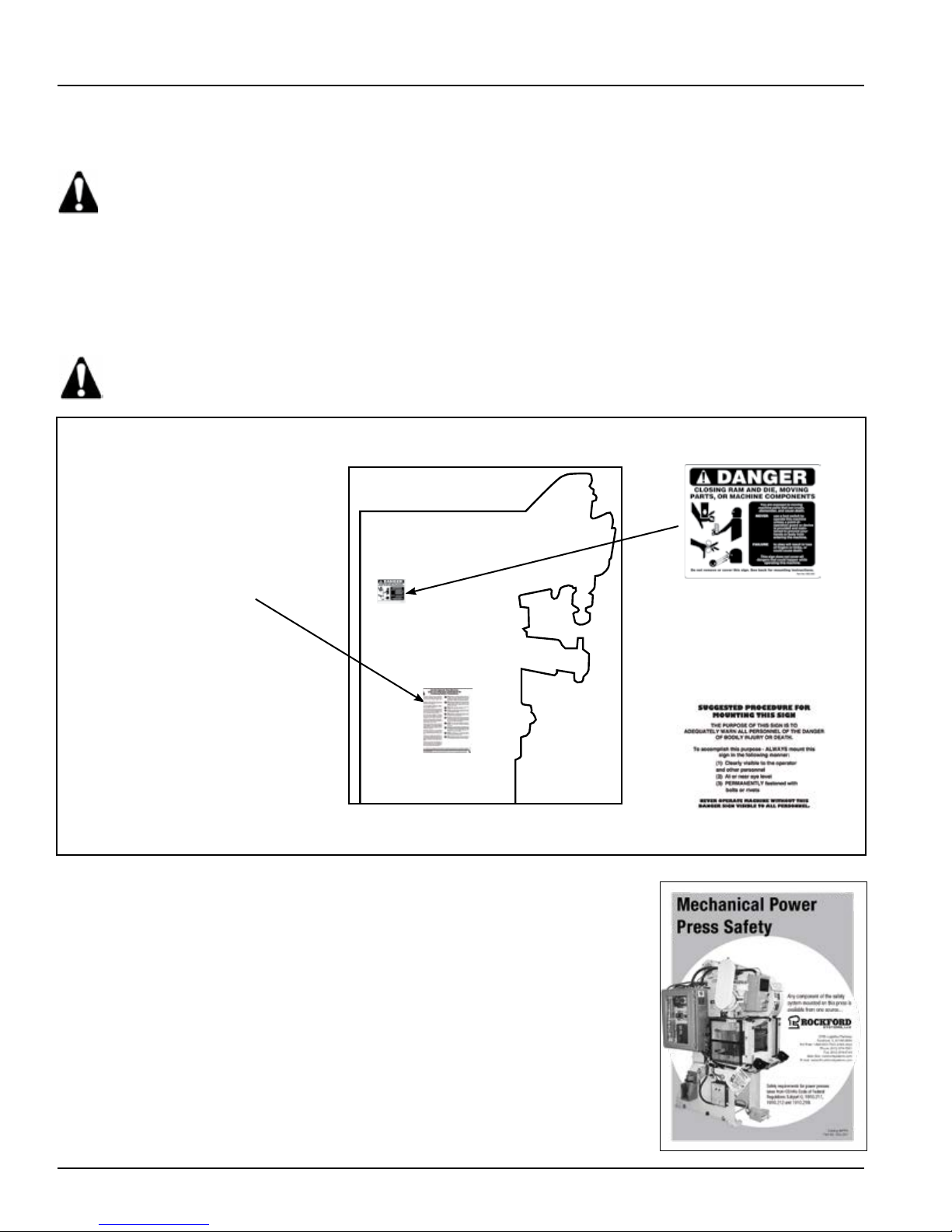
Danger Sign(s) to be Mounted on Machine
Accompanying this equipment is a 5” x 6” polyethylene danger sign, Part No. KSC-055. This sign MUST
BE PERMANENTLY MOUNTED IN A PROMINENT LOCATION on the machine where this equipment is
installed. This sign must be in a LOCATION THAT IS EASILY VISIBLE to the operator, setup person,
or other personnel who work on or around this machine. ALWAYS mount this sign with bolts or rivets
when installing the enclosed equipment.
If any danger sign becomes destroyed or unreadable, the sign must be replaced immediately. Contact factory for
replacement danger sign(s).
Never operate this machine unless the danger sign(s) is in place.
Part No. KSC-000 Operator
Safety Precations Sign
“M
echanical Power Press Safety
A copy of Booklet No. MPPS (Mechanical Power Press Safety) is available
upon request. This booklet is copied verbatim from the CFR (Code of Federal
Regulations) and contains all relevant sections of the OSHA standards concerning
power presses with which an employer (user) must comply. The enclosed
equipment must be installed, used and maintained to meet these standards.
Specically, any time a foot switch is used, a suitable point-of-operation
safeguard or device must be used to prevent bodily injury. In addition, every
press must be provided with a point-of-operation safeguard! Please review
this booklet before installing the enclosed equipment. If you are unfamiliar with
these detailed safety regulations, which include regulations on safeguarding
the point of operation properly, you may want to attend our regularly scheduled
machine safeguarding seminars. To obtain detailed information about these
training seminars, please call, fax, write, or check our Web site. Our telephone,
fax number, Web site, and mailing address are on the front cover of this manual.
” B
ooklet
Front Side
Part No. KSC-055 Danger Sign
(Foot) - Standard
Part No. KSC-055S - Spanish
Part No. KSC-055F - French
Reverse Side
6 Call 1-800-922-7533
Rockford Systems, LLC
Page 7

SECTION 1—IN GENERAL
Detect-A-Finger® Drop Probe Device-Welder
General Overview
The purpose of the Detect-A-Finger® Drop Probe Device is to effectively reduce accidents on applications where the
operator’s ngers may enter the point of operation. The components of this system are a sensing probe shaped to t
over or around the workpiece, a drop-probe assembly, and a control box. When the operator initiates a weld cycle,
the sensing probe is released and drops by gravity over or around the workpiece. If the operator’s ngers are still in
the danger area, the sensing probe cannot reach its preset down position and the welder is prevented from cycling.
Conversely, if no obstruction prevents the sensing probe from dropping, then as soon as it reaches its preset down
position, the control unit will allow the welder to cycle.
The control unit is ruggedly built to assure continued successful operation under adverse operating conditions usually
found around this type of machinery. For additional safety, the control relay in the control unit (when properly wired into
the machine system) will prevent cycling of the machine accidentally or intentionally. This can be conrmed by moving
the sensing probe manually without actuating the operating means.
Components in the System
• Control box
• Drop-probe assembly
• Sensing probe (2)—to be formed by user
• Sensing probe clamp
• Danger signs
Additional components that may be required
• Disconnect switch
• Transformer
• Lockout valve
• Foot switch
For mechanically operated welders:
• Air cylinder assembly
• Solenoid air valve
• Air lter-regulator-guage and lubricator assembly
Specications
®
Detect-a-Finger
CONTROL BOX
Input voltage ......................................................................................................................... 115 + 15% VAC, 50/60Hz
Operating current ................................................................................................................................. 0.6 Amps typical
Weight .......................................................................................................................................................approx. 8.5 lb
SENSING PROBE ASSEMBLY
Input voltage ........................................................................................................................... 24 + 15% VAC, 50/60Hz
(supplied from control box)
Operating current ................................................................................................................................. 3.0 Amps typical
Duty cycle ...................................................................................................25% (10-second max. continuous on-time)
Stroke .................................................................................................................................. 1.63 (15⁄8) inches maximum
Mechanical life ................................................................................................. Rotary solenoid–100 million operations
Weight .......................................................................................................................................................approx. 3.5 lb
Assembly—RKC-500
SENSING PROBE (UNFORMED)
Wire size ............................................................................................................................... .156 dia. x 18 inches long
Material ...................................................................................................................................Aluminum rod (standard)
Total weight ................................................................................................................... approx.0.5 lb (probe and clamp)
Rockford Systems, LLC
Call 1-800-922-7533
7
Page 8

SECTION 2—INSTALLATION OF COMPONENTS
Detect-A-Finger® Drop Probe Device-Welder
Preliminary Steps Before Installation
Before proceeding with the installation of the enclosed equipment, you should undertake the following preliminary
steps.
1. Read and make sure you understand this entire installation manual.
2. Refer to the front cover, other line drawings and photos, then make a sketch of your installation to plan the location
of the enclosed equipment on the machine.
3. Please make sure the machine is in rst-class condition. Before starting any installation, it is essential that
the machine is thoroughly inspected. Be sure all mechanical components and all collateral equipment are in rstclass operating condition. Your inspection should be done according to the machine manufacturer’s installation
and maintenance instruction manual. If you have any doubts or questions concerning the condition of the machine,
contact the machine manufacturer for assistance. Repair or replace all parts not operating properly before
proceeding.
Inspection and maintenance programs must be established and implemented to keep machines in
rst-class condition. Safety programs must include thorough inspections of each machine on a weekly
basis and records kept of these inspections. Any part of the machine that is worn, damaged or is not
operating properly must be replaced immediately or repaired before the machine is used.
4. Verify that the machine is in rst-class condition and operating properly; shut off all power to the machine. Padlock
all electrical and pneumatic energy in the off position and do not actuate the machine again until the installation of
all package components has been completed. Lockout/tagout energy isolation procedures must always be practiced
and enforced.
The operator must be protected from all hazards. All applicable sections of OSHA Section 1910.212
must be complied with on all machines where this equipment is installed.
The Detect-A-Finger® controls are applicable on most types of resistance welders. The function of the
Detect-A-Finger® device, when properly installed, adjusted and maintained, is to keep the operator from
inadvertently cycling the machine with ngers in the point of operation. This control only provides
an interface between the foot switch and the welder controller which will not allow stroke initiation
unless the area being probed is cleared of all obstructions. To accomplish this protection, the DetectA-Finger® must be properly installed on the machine and the device must be properly maintained and
adjusted by the user. A properly designed sensing probe must be used and additional sensing probe
safeguarding must be provided where applicable. This device does not protect the operator if ngers
are placed above the sensing probe.
Before starting any installation work, it is imperative the welder be inspected to exhibit proper operation.
Run the welder in a normal operating sequence to determine proper operation. Do not install the Detect-AFinger® on a welder that does not function properly. When the welder is operating satisfactorily, shut off
the power with the disconnect switch and do not operate the welder again until installation is complete.
Use of a lockout device and padlock on the disconnect handle must be used during this period.
The maintenance and inspection section in this manual cannot be all-inclusive for maintaining welders.
Always refer to the original welder manufacturer’s maintenance manuals or owner’s manual. If you do not
have an owner’s manual, please contact the welder manufacturer.
NOTE: The Detect-A-Finger® does not change the operation of the machine. This interface only interrupts the
foot switch signal. If this welder is capable of continuous operation while the foot switch is held, then
an interface will be required to have the sensing probe drop before each cycle of the welder.
8 Call 1-800-922-7533
Rockford Systems, LLC
Page 9

SECTION 2—INSTALLATION OF COMPONENTS
Detect-A-Finger® Drop Probe Device-Welder
Control Box
The RKC-500 series Detect-A-Finger® system control box is housed in a NEMA enclosure (approximately 61⁄4” wide
by 91⁄2” high by 41⁄2” deep) and consists of a through-the-door fuse holder, relay, terminal strips, transformer, and PC
board assembly. Mount the control box in a convenient location—the area around the control box should be kept clear
and be easily accessible for wiring and maintenance.
All electrical power to the machine must be off before mounting, wiring, or servicing the control box.
Fuse and Fuse
Holder
Terminal Strips
Relay
Transformer
PC Board Assembly
Rockford Systems, LLC
Call 1-800-922-7533
9
Page 10

SECTION 2—INSTALLATION OF COMPONENTS
Detect-A-Finger® Drop Probe Device-Welder
Sensing Probe Assembly
The drop rod is allowed to drop by gravity when the rotary solenoid is energized. The action arm return spring returns
this assembly when the power is removed. The DC voltage for the rotary solenoid is obtained from a full-wave bridge
rectier. The drop rod is guided in nylon bearings for long life and smooth operation. The limit switch actuates the
control relay in the control box at the end of the drop rod stroke.
Mount the sensing probe assembly as far forward as possible to allow for adjustments and electrode maintenance,
and to provide for minimum angle of the sensing probe. This position will also contribute to a long mechanical life of
the device since it minimizes the side loading on the drop rod bearings.
Rotary
Solenoid
Return
Spring
Drop
Rod
Drop
Rod
Arm
Limit
Switch
Bridge
Rectier
10 Call 1-800-922-7533
Rockford Systems, LLC
Page 11

SECTION 2—INSTALLATION OF COMPONENTS
Detect-A-Finger® Drop Probe Device-Welder
Sensing Probe
Two 18-inch pieces of 5⁄32 (.156) inch diameter aluminum rods are furnished with each Detect-A-Finger®. Other
materials or custom made congurations may also be used. The only restriction is the total weight of the probe
assembly (including the clamp). The action-arm return spring is capable of returning 0.5 pounds maximum. The user
must determine and form the best shape to accommodate the particular part being run. This device must be designed,
constructed and arranged to create a protected area, and to prevent engagement of the machine. In pneumatic and
hydraulic-powered machines, this device must prevent energizing of the control valve when an operator’s nger or other
part of the body is within the hazardous area.
The bottom of the drop rod, in its full down position, should barely clear the workpiece. This location allows for nal
positioning. If special mounting brackets are fabricated, they must be able to support the sensing probe assembly and
withstand any shock and vibration that may be encountered during machine operation. Be sure to insulate any and all
special brackets from the electrodes.
Examples of how the drop-probe rods can be fabricated
TYPICAL APPLICATIONS
PRESS-TYPE RESISTANCE WELDER ROCKER-ARM-TYPE RESISTANCE WELDER
Detect-A-Finger® Sensing-
Probe Assembly
Detect-A-Finger®
Control Box
Foot Switch
To Welder
Controller
To
Power
115 V AC
Detect-A-Finger®
Sensing Probe
Assembly
Sensing Probe
Detect-A-Finger®
Control Box
Foot Switch
Transformer
(if required)
To Welder
Controller
Main
Power
Disconnect
Switch
Sensing
Probe
Rockford Systems, LLC
Call 1-800-922-7533
11
Page 12

SECTION 2—INSTALLATION OF COMPONENTS
Detect-A-Finger® Drop Probe Device-Welder
Other Components That May Be Required
Main Power Disconnect Switch
A main power disconnect switch may have been supplied in the package shipment. This switch is designed to
disconnect the primary voltage to the machine and lock it out. Refer to the enclosed wiring schematics for proper wiring
of this switch.
OSHA regulation 1910.217 (b)(8), ANSI standards B11.1 and B11.3 require that:
A main power disconnect switch capable of being locked in the off position shall be provided with every control system.
If the machine already has a main power disconnect switch, it must be checked for the locking off and lockout feature.
Some switches use construction which can be easily altered mechanically to comply with this requirement. If this is
not possible, or an electrical disconnect switch is not provided, then you must obtain and install a proper disconnect
switch. Please contact Rockford Systems, LLC if a disconnect switch is needed.
Transformer—Part No. RSF-021
An enclosed transformer—Part No. RSF-021—may have been supplied with this shipment. This enclosed transformer
is a 100-VA, 230/460-V primary and a 115-V fused secondary unit. The fuse is 1 A, 230 V and it is accessible from the
outside of the transformer housing.
Air lockout valve
(If furnished—See enclosed manual KSL-098)
An air lockout valve is usually attached to the inlet end of a lter-regulator-lubricator assembly.
This three-way valve is operated with the manual movement of a slide that opens and closes the
valve. The valve can only be locked out when the slide is in the closed position. Downstream air
is automatically exhausted when the valve is locked out.
Air Lockout Valve
Foot Switch (If furnished—See enclosed manual KSL-001)
To meet OSHA and ANSI safety requirements, a foot switch must be protected
from unintentional operation. This foot switch pedal is protected on the top and
both sides by the cast cover and the front is protected by the hinged ap. Always
follow the wiring schematics for proper wiring connection and be sure to maintain
the foot switch in rst-class condition.
It is the responsibility of the employer (user) to always provide an
appropriate guard and/or device to prevent bodily injury whenever a
foot switch is used to initiate a machine cycle.
The guard and/or device must be properly installed, used, and
Foot Switch
Part No. CTD-011
maintained. The safeguard must prevent personnel from receiving
bodily injuries.
12 Call 1-800-922-7533
Rockford Systems, LLC
Page 13

SECTION 2—INSTALLATION OF COMPONENTS
Detect-A-Finger® Drop Probe Device-Welder
Other Components That May Be Required For Mechanically
Operated Welders
Most welders are controlled electrically, pneumatically or mechanically; if not, other components may be required.
Review this section for typical applications of the Detect-A-Finger®. Accessory equipment and components, such as
solenoid air valves or air cylinders are available from Rockford Systems for your convenience. If you require assistance
on the application of such components, please contact the factory.
Mechanical to Electro-Pneumatic Conversion—Convert from mechanical operation by removing the treadle and
replacing it with an air cylinder. The cylinder bore and stroke (push or pull type) can be determined from actual
machine measurements and the location of attachment to the welder linkage. The air cylinder is controlled by a 3-way
normally closed 120 VAC solenoid air valve. Adjustable ow control valves may be employed to smooth the welder
arm movement and a lter-regulator-lubricator and pressure gauge assembly is also required. The Detect-A-Finger®
controls the solenoid air valve.
RCL Series Air Cylinders (If furnished—See enclosed manual KSL-096)
One of the following pull-type air cylinders may be adequate to operate the welder:
Single-acting spring-return air cylinders are usually supplied with a swivel-clevis mount as standard. Other special
cylinders, such as clevis mount, ange mount (either end) or foot mount are also available. They can be push-type
(spring inside cylinder), or pull-type (spring on cylinder rod, as illustrated above). The main consideration must be that
the cylinder is a single-acting spring-return type (not double acting) to meet best safety practices. When mounting
the cylinder, be sure it is secured in such a manner that it will not vibrate loose, bind or rub on some other part of the
machine.
RCL-001 RCL-002 RCL-003
Machine Size
(Tons)
Size
(Bore x Stroke)
Pull Force
(@ 75 PSI)
NPT Port
Size
¼ to 7
¼” ¼” ¼”
8 to 35
1
/8” x 1”
1½
” x 1”
1
50 lb 100 lb 200 lb
2
36 to 70
” x 2”
Pull-Type Air Cylinder
zThe assembly consists of the cylinder, two mounting feet, mounting pin, drive yoke, drive pin, and yoke lock nut. This
assembly is illustrated at the bottom of page 14. Locate this assembly on the machine so that the feet can be mounted
to a convenient surface. The yoke should be attached to the welder linkage, and the air inlet should be oriented toward
the air solenoid valve location.
The air cylinder should be mounted in the most logical position to operate the welder linkage most efciently. The
main requirement in locating the cylinder assembly, is that the piston rod will have a straight, in-line pull (or
push) when attached to the operating linkage. When applying an air cylinder to the machine, make sure that
the cylinder rod, yoke or any moving parts will not bind after installation. Adjust so that the air cylinder bottoms
at the end of each stroke. The air cylinder will operate in any position. The operating linkage may be connected to
the air cylinder by any convenient means. Be sure the rod stroke is not too long because it could cause jackkning of
the cylinder. If this is a concern shorter stroke cylinders are available. Too much air pressure may damage the operating
linkage. Please consider these points when installing any air cylinder.
Make certain that the drive yoke and lock nut are located approximately halfway down on the threaded portion of the
piston rod in order to provide for either up or down adjustment when necessary. Attach one end of the exible rubber
hose in the threaded cylinder inlet port and tighten rmly.
Note: Threaded air joints do not generally require sealant; however, “Teon” tape may be used to prevent leakage.
Rockford Systems, LLC
Call 1-800-922-7533
13
Page 14

SECTION 2—INSTALLATION OF COMPONENTS
Detect-A-Finger® Drop Probe Device-Welder
Other Components That May Be Required For Mechanically
Operated Welders (continued)
Solenoid AiR Valve Assembly (If furnished—See enclosed manual KSL-151)
The solenoid air valve is a three-way, normally closed, quick exhaust type. This
assembly consists of the electric air solenoid valve, steel mounting bracket, and
exible hose. Assemble the mounting bracket to the base of the valve and orient
this assembly so that the air outlet port (marked “1” on the valve body) points
toward the air cylinder and is within reach of the exible hose. Next attach this
hose to the No. 1 port of the solenoid valve and mount the valve assembly on the
machine allowing sufcient exibility to accommodate cylinder movement. (See
Solenoid Air
Valve Assembly
Part No. RCD-006
Mount the solenoid valve assembly in a vertical position. The electrical conduit tting can be easily adjusted to face in
any horizontal direction by loosening the hex nut at the top and turning the enclosure. Retighten this nut after locating
the tting. Saddle-clamp type terminals are provided on the solenoid for wiring.
diagram below.) It is extremely important to use the rubber hose provided for
the connection between the solenoid valve and the air cylinder. It provides
the necessary exibility, size and length for proper exhaust of cylinder air,
all of which are required for successful machine operation.
Exhaust air mufer must be kept clean at all times. Never operate machine unless mufer is clean.
Yoke Pin
Drive Yoke
Yoke Nut
Cylinder Return
Spring
Provide loose
ring guide in
either of these
areas if
necessary to
limit cylinder
side-to-side
motion
Air
Cylinder
Cylinder
Inlet Port
Flexible Hose
Air Cylinder and Solenoid
Air Valve Connection
Solenoid
Air Valve
2
1
Electric
Conduit
Fitting
Air Inlet Port
Mounting
Feet
14 Call 1-800-922-7533
Air Outlet
Port
Solenoid Mounting
Bracket
Rockford Systems, LLC
Page 15

SECTION 2—INSTALLATION OF COMPONENTS
Detect-A-Finger® Drop Probe Device-Welder
Other Components That May Be Required For Mechanically
Operated Welders (continued)
Filter-regulator-lubricator (frl) assembly (If furnished—See enclosed
manual KSL-208)
The lter cleans air that goes to the solenoid air valve (and air cylinder, if furnished). The regulator and gauge are used
to adjust air pressure. The lubricator keeps the solenoid air valve or the air cylinder (if required) properly lubricated.
The lter-regulator unit with one threaded pipe plug, lubricator, gauge, mounting bracket, and a connector or nipple
are shipped together.
Filter-Regulator
Combination
Filter-Regulator-
Lubricator Assembly
Part No. RCL-043
The air lter must be kept clean at all times. Never operate the machine unless the air lter is clean.
The lubricator must not be lled while under pressure.
Lubricator
Unpack the lter-regulator unit and install the connector between the lter-regulatorlubricator (see arrow for air ow direction). Tighten this assembly and position the two
units with both bowls in alignment. Be sure to check air ow direction and the location
of the valve to avoid excessive piping.
Choose an appropriate location on the machine for mounting this assembly. If possible,
it should be accessible from oor level.
Install the pressure gauge in the threaded port opposite the mounting surface and plug
the unused port. Attach the mounting bracket to the machine and then mount the FRL
assembly using the lock nut supplied.
The length of the air line run is not critical; however, the port and pipe sizes should be
maintained.
Fill the lubricator with a good quality lubricant (see OEM’s specications) to the level
indicated by the maximum ll line on the transparent reservoir. Do not overll. When
the machine is cycled, the lubricator drip rate may be adjusted according to the
instruction manual. Please check the machine owner’s manual for proper specications
for oil, if required. Some clutch and brake assemblies do not require lubrication.
Regulate the air pressure high enough to develop sufcient pull (or push) to operate the welder mechanically.
Never apply more than 145 PSI.
Bring shop air supply to the welder. Connect the air supply at the threaded opening, indicated as In by the
direction arrow on the lter-regulator. Maintain minimum 1⁄4” pipe size.
Important—Blow air line clear of all dirt, scale, etc., before connecting lter. Drain water out of
lter bowl when lled. If bowl lls with water in a short period of time, install a larger lter in
your main air supply line leading to the welder.
It is recommended that a manual shut-off valve be installed in the main line ahead of the
lter-regulator-lubricator assembly and close to the welder for convenience and lockout.
Rockford Systems, LLC
Call 1-800-922-7533
15
Page 16

SECTION 2—INSTALLATION OF COMPONENTS
Detect-A-Finger® Drop Probe Device-Welder
Other Installation ConsiderationS
PIPING
1. An air lockout valve must be installed in the air line usually just before the lter-regulator-lubricator assembly to meet
OSHA 29 CFR 1910.147 Lockout/tagout requirements. However, a separate lockout valve could be furnished for each
air system on the machine such as counterbalance, clutch/brake, air cylinder, and blow-off.
2. From the lockout valve, connect at the In threaded opening of the lter-regulator. Try to maintain an appropriate pipe
size throughout for proper air ow. Connect the piping to the ports using teon tape on the male threads only. Do not
allow tape to enter the interior of the lter-regulator-lubricator, valve, or air cylinder. Before applying air pressure, make
sure the lter and regulator bowls are at least hand tight.
3. Most approved pipe or hose can be used on the welder. Make sure the size is consistent throughout the system in
order to avoid restriction. Keep air runs as short as possible.
4. See enclosed lter-regulator-lubricator (FRL) assembly Manual No. KSL-208 for additional details.
All air components require clean air. Blow all lines clean of water, dirt, scale, etc., before making nal
connection. Drain water from lter bowl regularly. Should this bowl rell in a short period of time, it
CAUTION
WIRING
National Electrical Code and NFPA 79 practices are usually followed for wiring the system, which includes color-coding
and the use of numbered wire markers on both ends of every wire. The size of wire depends on local ordinance—number
14 stranded copper wire with an approved insulation is recommended.
may indicate the need for a larger lter in the main air supply line or an air line dryer system. The
air lter must be kept clean at all times. Never operate the machine unless the air lter is clean and
water is drained.
DO NOT USE SOLID WIRE.
1. Install and wire the main disconnect switch (unless one already exists) using black wire. Follow wiring instructions
shown on the electrical schematics. Make certain this switch is capable of being locked in the off position only.
Complete wiring diagrams are provided for connecting all controls and components properly. The foot switch should
be installed so it is readily available to the machine operator.
2. Bring 120 V AC 3-wire service to the Detect-A-Finger® control box. Ground should be connected to the green ground
screw. Connect the hot side of 120 V AC to terminal 1. Connect the common to terminal 2. If 120 V AC is not available
on the welder, then a transformer must be incorporated to step down the line voltage. This transformer must be rated
in accordance with load requirements.
3. Connect the foot switch as follows:
Single stage—NO contact to terminals 3 and 4
Two stage—NO contact of 1st stage to terminals 3 and 4
NO contact (NC held open) of 2nd stage to terminals 7 and 8
Connect a green wire from the ground terminal in the foot switch to the green ground screw in the Detect-A-Finger®
control box.
4. Connect the welder controller—terminal 5 to FS-1 and terminal 6 to FS-2. If two stage, connect terminal 8 to FS-3 and
terminal 9 to FS-4.
5. Connect the sensing probe assembly—connect the 5-conductor cable provided between the color-coded terminals
shown on the wiring diagram. W White, R Red, B Black, BR Brown, G Green Ground Wire
Note: The drop rod when activated will drop and then, if probe area is clear, the welder will cycle and the drop rod
will return immediately without releasing the foot switch. If the drop rod needs to stay down until the foot
switch is released, a jumper may be placed between the R and BR terminals.
16 Call 1-800-922-7533
Rockford Systems, LLC
Page 17

SECTION 3—OPERATING PROCEDURES & TROUBLESHOOTING
Detect-A-Finger® Drop Probe Device-Welder
Operating Procedure
1. Apply power. If the power does not come on, check that the main disconnect switch is on, fuse is connected, and check
for proper wiring.
2. Measure the incoming voltage at terminals 1 and 2. It should be 115 V AC ± 15%. Shut off power for the next step.
3. The sensing probe should be in position over the workpiece and formed to protect the required area. Move the drop rod
manually to the point where the limit switch (in the control box) is actuated and locate the sensing probe to be no more
than 1⁄4 inch above the workpiece. Check this adjustment periodically and before every setup.
4. Reapply power—the welder should be ready to cycle. Depress the foot switch. The Detect-A-Finger® rotary solenoid
should energize, permitting the drop rod to drop until the limit switch is actuated. The limit switch now energizes the
control relay and the relay contacts close, energizing the welder controller or operating device (solenoid). The welder
electrodes should close thus permitting the parts to be welded.
Troubleshooting
Voltage Measurement Troubleshooting
SYMPTOM TEST POINTS READING PROBLEM
0
60 V AC
230 V AC
115 V AC
0
115 VAC
0
24 V AC
0
24 V AC
0
24 V AC
0
24 VAC
Carefully check continuity with test light or ohmmeter when the foot switch is
depressed. The relay contact should close. If not, replace relay. If the relay
contact closes properly, the problem is with the welder operating device or
wiring is defective. Check continuity with an ohmmeter. Reconnect FS1 and 2.
Carefully check continuity with test light or ohmmeter when the foot switch is
depressed. The relay contact (Terminals 7-9) should close. The foot switch
contact (Terminals 7-8) should close. If not, replace the defective component.
If these contacts (Terminals 8-9) close properly, the problem is with the welder
controller. Reconnect FS3 and 4.
No primary power.
Transformer wired for 460 V AC, 230 applied.
Transformer wired for 230 V AC, 460 applied.
Proper voltage applied, continue.
Fuse blown, replace.
Defective lamp, replace.
Transformer defective, replace.
Proper voltage, continue.
Foot switch defective or improperly connected,
locate problem and correct.
Proper voltage, continue.
Relay contact (N.C.) defective, replace relay.
Proper voltage—bridge rectier or rotary solenoid
defective. See resistance measurement section.
Limit switch not being actuated or limit switch
defective. Replace limit switch.
Proper voltage—relay coil open.
“Power On” Indicator
Will Not Light
“Power On”
Indicator is Lit,
Rotary Solenoid
Will Not Energize
No Power
Rotary Solenoid
Will Not Energize
“Power On”
Rotary Solenoid
Energizes, Welder
Will Not Cycle
“Power On”
Rotary Solenoid
Energizes, Welder
1st Stage (Squeeze)
Operates, 2nd Stage
(Weld) Will Not Function
Terminal 1-2
Terminal 2 to wire common
with fuse and light to door
Terminal 3-W
Terminal 4-W with
foot switch depressed
Terminal BR-W with
foot switch depressed and
sensing probe held up
Terminal R-W
with foot switch
depressed
Disconnect FS1 and 2 from Terminals 5 and 6.
Terminals 5-6
(Single stage)
Disconnect FS3 and 4 from Terminals 8 and 9.
Terminals 7-9
and 7-8 (2nd stage)
Rockford Systems, LLC
Call 1-800-922-7533
17
Page 18

SECTION 3—OPERATING PROCEDURES & TROUBLESHOOTING
Detect-A-Finger® Drop Probe Device-Welder
Troubleshooting
Resistant Measurement Troubleshooting
TERMINAL
From To
a b
b a
a c
c a
d b
b d
d c
c d
RESISTANCE
OHMS
700
∞
700
∞
∞
700
∞
700
(a)
(b)
(c)
(d)
(-DC)
AC
AC
(+DC)
Power off with components not connected.
Bridge Rectier, Terminal Identication
Readings may vary slightly from meter to meter. However, the
trend established between innity (∞ ) and the lower readings
must remain consistent throughout the test. Any unusual reading
means the bridge rectier is defective and must be replaced.
Transformer: Primary - 20 Ohms approx.
Secondary - 2 Ohms approx.
Rotary Solenoid - Resistance 7.72 Ohms.
AC solenoid air valves of the type usually supplied by Rockford
Systems, LLC have approximately
100 Ohms DC resistance.
18 Call 1-800-922-7533
Rockford Systems, LLC
Page 19

SECTION 4—REPLACEMENT PARTS
Detect-A-Finger® Drop Probe Device-Welder
Replacement Parts
REPLACEMENT PARTS FOR CONTROL BOX RKC-501
Part No. Description
RFT-017 Relay
RSC-327 Transformer
RTY-003 Fuse 1 Amp
FTL-020 PC Board
REPLACEMENT PARTS FOR SENSING PROBE ASSEMBLY RKC-502
Part No. Description
CMF-108 Rotary Solenoid
FKC-101 Spring
CMC-020 Limit Switch
FTL-020 PC Board
REPLACEMENT KITS
Part No. Description
FCT-042 Hardware Mounting Kit
FCT-044 Drop Rod Assembly Repair Kit
FCT-041 Sensing Probe and Clamp
Rockford Systems, LLC
Call 1-800-922-7533
19
Page 20

SECTION 5—ORDER FORM FOR SIGNS & LITERATURE—RMA FORM
Detect-A-Finger® Drop Probe Device-Welder
ORDER FORM FOR SIGNS AND LITERATURE
This instruction manual references signs and literature available for your machines. This order form is for your
convenience to order additional signs and/or literature as needed. (This order form is part of your installation
manual so please make a copy of it when ordering.)
Company
Address
City State Zip
Phone Fax
Name Purchase Order No. Date
Part No. Description Quantity Required
KSL-022 Instruction Manual—Detect-A-Finger® For Welder
KSC-000 Operator Safety Precautions Sign—Metalforming (English)
KSC-000S Operator Safety Precautions Sign—Metalforming (Spanish)
KSC-000F Operator Safety Precautions Sign—Metalforming (French)
KSC-055 Danger Sign (Closing Ram and Die) 5” x 6” (English)
KSC-055S Danger Sign (Closing Ram and Die) 5” x 6” (Spanish)
KSC-055F Danger Sign (Closing Ram and Die) 5” x 6” (French)
KSL-051 Mechanical Power Press Safety Booklet
For prices and delivery, please use address, phone or fax number listed on the front cover of this manual.
Your Signature Date
RETURN MATERIALS AUTHORIZATION REQUEST FORM
To return material for any reason contact the sales department in our organization at 1-800-922-7533 for an
RMA Number. All return materials shipments must be prepaid. Complete this form and send with material to
5795 Logistics Parkway, Rockford, IL 61109. Make sure the RMA Number is plainly identied on the outside of
the shipping container.
Company
Address
City State Zip
Phone Fax
Contact Name Representative
Items Authorized To Return on RMA No. Original Invoice No. Date
Part No. Serial No. Description
Service Requested: Full Credit 25% Restocking Repair & Return Warranty Replacement
Reason for return (describe in detail):
Return Materials Authorized By Date
KSL-022/RSI/1018
 Loading...