

Page 1
INSTALLATION MANUAL
AF/4HD ACTIVE FILTER ADJUSTABLE CROSSOVER
Page 2
PRACTICE SAFE
CONTINUOUS EXPOSURE TO SOUND PRESSURE LEVELS OVER 100dB MAY CAUSE
PERMANENT HEARING LOSS. HIGH-POWERED AUTOSOUND SYSTEMS MAY PRODUCE
SOUND PRESSURE LEVELS WELL OVER 130dB. USE COMMON SENSE AND PRACTICE
SAFE SOUND.
SOUND™
Make your
from
man about Perfect Power alternators power cables, speaker wire
cosmetic
%ckhrdfbqak
ibdbdb%?db@ a division of
accessories
and
system complete
fabric.
Rockford
with
installation
Corporation. Ask your
accessories
sales-
connectors
Page 3

.
TABLE OF CONTENTS
Introduction.. .......................................................................................................................................................
Input and Output Levels .....................................................................................................................................
Power Wiring Instructions ...................................................................................................................................
Fuse Protection ..................................................................................................................................................
Figure 1 Illustration View....................................................................................................................................
Frequency Selection
Band Selection ...................................................................................................................................................
Figure 2 Illustration View
Switching Examples ..........................................................................................................................................
Summing Channel ..............................................................................................................................................
Phase Shift and Cancellation .............................................................................................................................
Extra Features ....................................................................................................................................................
Active vs. Passive Crossovers
Specifications
Warranty Information ..........................................................................................................................................
...........................................................................................................................................
....................................................................................................................................
...........................................................................................................................
.....................................................................................................................................................
1
1
1
1
2
2
4
6
7
9
9
11
11
14
15
Page 4

INTRODUCTION
The
Design) to provide state-of-the-art flexibility, performance and pleasing aesthetics. Its features
include: four stereo inputs with true fading capability, infinitely adjustable frequency modules,
four user definable high pass, low pass and band pass filters, single channel summing for mono
applications, fully isolated high voltage power supply, low noise circuitry, low distortion, high
load driving capacity 750 mV RMS input level, 750 mV RMS output level.
.
.
.
.
.
.
.
.
.
.
.
.
Rockford Fosgate AF/4HD is an active electronic crossover that incorporates HD (Hybrid
FADING CAPABILITY
ONE CHANNEL CAN BE SUMMED FOR MONO APPLICATIONS
TWO USER SELECTABLE FILTERS (HIGH PASS OR LOW PASS)
TWO USER ADJUSTABLE BAND PASS FILTERS THAT CAN ALSO
BE SELECTED AS HIGH OR LOW PASS FILTERS
CAPABLE OF UTILIZING ONE TO FOUR INPUTS
GOLD PLATED RCA’S
INTERNAL FUSE FOR PROTECTION
CONCEALED MOUNTING
AUDIO CIRCUIT IS HYBRID DESIGNED
LOW DISTORTION
WIDE RANGE OF FREQUENCY MODULES, OR FASHION YOUR OWN
SMALL, LOW COST
.
HIGH LOAD DRIVING CAPACITY: CAPABLE OF HANDLING UP TO 10
ROCKFORD FOSGATE AMPLIFIERS
.
12dB/OCTAVE CROSSOVER SLOPES
.
CASCADING OF OUTPUT TO INPUT PROVIDES 24dB/OCTAVE SLOPE
INPUT AND OUTPUT LEVELS
The AF4 is designed for preamp-level (750 mVRMS) levels. Speaker-level inputs must be
attenuated to under 1.0 VRMS.
Net gain in the filter passband of the AF4 is unity. (output levels are equal to input levels)
POWER WIRING INSTRUCTIONS
The Black 16-gauge wire should be grounded to the chassis. The White (or white with a red
stripe) 16-gauge wire should be connected to a source of constant 12-Volt power. The Red
gauge wire is the remote turn-on wire. Connect it to the radio “Auto-Antenna” lead, or to some
other point that goes “positive” when the system turns on. See Figure 1.
PROTECTION FUSE
The AF4 has a built-in main power fuse for over current protection. If blown, replace with AGC
1/2
amp fast blow fuse. See Figure 1 for fuse location.
16-
1
Page 5
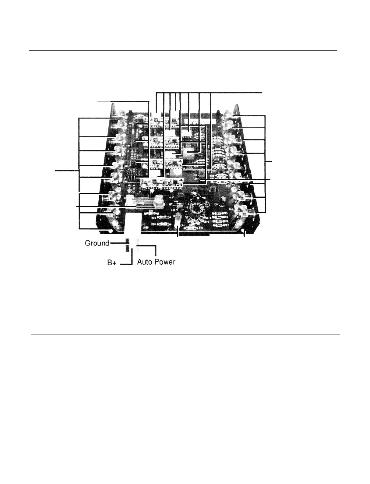
AF/4HD WIRING/FUSE/MODULE AND JUMPER LOCATIONS
Inputs
Modules For Band
Switches For Number
Of Inputs And A
Summing Channel
7
Fuse
1/2
Amp
Fast Blow
And Frequency/
-
outputs
Circuit Hybrids
FREQUENCY SELECTION
Custom crossover frequency modules will allow you to create notch filters oroverlapfrequencies
to “equalize” in or out a desired response.
High and Low crossoverfrequencies in the AF4 are selected by inserting frequency modules in
sockets in the internal PC board.
In order to change a frequency module, remove the four machine screws that hold the cover and
remove the cover. Remove the frequency module you wish to change, and insert the new
module in its place.
L
Power LED
FIGURE 1
L
Mounting Holes
&
Locations
See Fig. 2 for module locations.
WARNING! TURN OFF SYSTEM BEFORE REMOVING MODULES!
2
Page 6

BUILDING A CUSTOM CROSSOVER MODULE
,
If you want a frequency not available in the standard
half-octave intervals from 50 Hertz to 9,000 Hertz), you can, in fact, build your own module.
You will need:
1. An 8-pin DIP component carrier
2. Soldering equipment
I
3. A source of
Determine the resistance value you need for the frequency you want from the formula below.
R=
1 .38 (10
“f"
is the frequency that you want.
1/4-watt
1
-
7
)f
or
OHM’s
FREQUENCY RESISTOR VALUES
The following table was tabulated by using the formula that was given earlier.
Frequency Resistance
50 Hz
70
Hz
100 Hz
150 Hz
200
Hz
275
Hz
400
Hz
550 Hz
750
Hz
150k
Ohms
OOk
Ohms
1
75k Ohms
47k Ohms
36k Ohms
27k Ohms
18k Ohms
13k Ohms
9.7k
Ohms
Rockford
1/8
watt resistors. (Preferably 1% resistors)
modules (which are available at
Frequency Resistance
80 Hz
1k
Hz
1.5k
Hz
2k Hz
3k Hz
4.5k Hz
6.5k Hz
9k Hz
13k Hz
9.1 k Ohms
7.5k
Ohms
4.7k
Ohms
3.6k
Ohms
2.4k
Ohms
1.6k Ohms
1.1k Ohms
820
Ohms
557
Ohms
3
Page 7

Page 8

The selection is done simply by placing the capacitor module (C) in the socket location on the
PC board marked “High” for high pass or “Low” for low pass. The empty location is where the
resistor frequency module (R) is placed. See below.
Note: Outputs one andfourcan be defined as either a high pass or low pass depending on where
the capacitor module (C) is placed. Outputs two and three are set band passes.
HIGH
HIGH
mm
HIGH
mm
mm
LOW
LOW
LOW
HIGH
HIGH
LOW
LOW
HIGHPASS
BANDPASS
BANDPASS
HIGHPASS
5
Page 9

AF/4HD
BAND & FREQUENCY
MODULE LOCATIONS
High Pass Location
Resistor Module
Low Crossover
Point
High Pass
Location
Capacitor Module
7
Low Pass Location
Capacitor Module
Crossover
Point
Low Pass
Location
-
Crossover Module
FIGURE 2
6
Page 10

Page 11

Page 12

SUMMING CHANNEL
The Summing Channel can be defined as summed or non summed by moving the jumper
switchers to the summed or non summed positions. (See diagram below)
PHASE SHIFT AND CANCELLATION
The filter sections used in crossovers (both active and passive) change the phase of the input
signal as well as the amplitude. In effect, phase shift moves the output forward or backward
compared to the input. Phase shifting is measured in degrees. One full cycle is 360°, so
output signal moves back
Cancellation is what happens when one speaker is pushing while the other is pulling. Instead
of putting out sound into the environment, the speakers just swap air back and forth. (This is what
happens when stereo speakers are hooked up out of phase).
The phase shift of crossover filters can cause cancellation. The drawing of the 90° leading and
lagging waveforms above shows that the leading wave is negative when the lagging wave is
positive. If each output went to a speaker, the speakers would be out of phase and cancellation
would occur.
The Phase shift at Cutoff table shows that 12dB/Octave filters have +90° and -90° phase shifts
at cutoff, and therefore they will produce cancellation unless something is done.
1/4
cycle, the phase shift is
9
1/4
of 360°, or -90°.
if the
Page 13

INPUT I TWO CYCLES 1
SE?
PHASE LAG
PHASE SHIFT AT CUTOFF
High Pass Low Pass
12dB/Octave +90°
24dB/Octave +180°
When a high and low-pass of 12dB/Octave filters is used, cancellation can be avoided by one
simple step:
-
Reverse the woofer phase by reversing the wiring to the + and - terminals.
Reversing the woofers has the effect of putting the woofer and midrange back in phase at the
crossover frequency to compensate for the crossover’s phase reversal.
On speaker systems where the woofer and midrange speakers are separated by more than
a couple of feet, the travel time of sound through air can produce a phase lag leading to
cancellation. For this reason:
-On any installation try reversing both woofer phases. In some cases bass will be much tighter
with woofers reversed.
-90°
-180°
These considerations also apply to the midrange-to-tweeter crossovers, although usually the
problems introduced are less audible. The cure is the same, but applied to the tweeter:
-
Reverse the tweeter phase by reversing the + and - terminals.
In general, the acoustics of cars and the variations of speaker placement can produce a variety
of unexpected cancellations. Where possible, experiment with speaker phase by comparing
the sound of the system with in-phase and reversed phase locating the smoothest-sounding
connection.
Also, unused inputs can be used as non filtered outputs.
Any combination of features can be used simultaneously. (See example below)
Page 14

EXTRA FEATURES
Cascading from output to input to create 24dB per Octave slope.
ACTIVE - VS - PASSIVE CROSSOVERS
All crossovers are frequency divider networks. Both active and passive crossovers
audio frequencies before they arrive at the speakers, and pass to each speaker only the desired
frequencies. An active crossover is an electronic “black box” (i.e. the
circuitry for frequency separation, and requires an electrical power supply. Passive crossovers
go between the amplifier and the speaker, using bulky indicators and capacitors. Passive
crossover components for low frequencies are particularly large and heavy. By contrast, active
crossovers separate frequencies with the same high and low pass filter functions as passive
crossovers, but since they are made with integrated circuits, they are much smaller and lighter.
Passive crossovers are usually much cheaper to use, since an additional amplifier isn’t needed.
However, there are a number of disadvantages to passive crossovers.
.
FREQUENCY CONTROL: The response of a passive crossover depends strongly on the
characteristics of the particular speaker.
.
CROSSOVER SLOPE: Single component passive crossovers (1 cap or 1 inductor) only
provide 6dB per octave
time and expense.
.
FREQUENCY CHANGING: Components for a wide variety of passive crossover frequen-
cies are difficult to stock and inconvenient to change.
All these disadvantages are reduced or eliminated with the use of an active crossover/amplifier
system.
rolloff. 12dB
separate the
AF/4HD)
per octave passive crossover require more design
containing
11
Page 15

CHOOSING CROSSOVER FREQUENCIES
Choosing the correct crossover frequency can be difficult. Consideration of the following items
will help you make your selection easier.
OPERATING RANGE OF SELECTED DRIVERS:
Manufacturers will usually provide information about the operating range of theirdrivers so that
you can choose a crossover frequency within that range to obtain maximum performance.
DESIRED POWER HANDLING OF DRIVERS:
Most autosound installations introduce a number of acoustical problems that can sometimes
be corrected with careful attention to your crossover frequencies. The use of
can help you determine if a problem exists and at what frequency.
l/3
octave RTA
The following crossoverfrequencies work the best with
a good foundation for any autosound system.
Woofer 100 Hz Low-pass
M idbass 100 Hz High-pass-275 Hz Low-pass
Midrange 275 Hz High-pass-9 kHz Low-pass
Tweeter 9
NOTE: Depending on the desired response of a given system, crossover frequencies can be
varied accordingly.
kHz
High-pass
Rockford
Fosgate drivers, and provide
12
Page 16

Page 17

AF/4HD SPECIFICATIONS
Input Level:
Input Impedance:
Output Level:
Output Impedance:
Signal-to-Noise Ratio:
Distortion:
Frequency Response:
Filter Response:
Filter Slope:
Power Required:
Dimension:
Weight:
750 mV RMS
20,000 Ohms
750 mV RMS
500 Ohms
90dB
Over
Under
20 Hz-20,000 Hz -.5dB
Butterworth
12 dB per Octave
Positive 12 Volts Required
5.5” wide x 5.75” long x 1.25” high
139.7mm x 146mm x 31.75mm
21 oz.
(A-Weighted)
.01%
THD + Noise
14
Page 18

LIMITED WARRANTY
ELECTRONIC WARRANTY
.
Rockford
and one year labor providing product was purchased from and installed by an authorized
Rockford Fosgate dealer. Warranty on product purchased from but not installed by an
authorized dealer is one year parts.
Fosgate warrants electronic components to the original purchaser for two years parts
Proof of purchase must accompany returned product.
SPEAKER WARRANTY
Rockford
providing the product was purchased from and installed by an authorized
dealer.
processed through authorized dealers. SHOULD YOU NEED TO OBTAIN SERVICE ON
ELECTRONICS OR SPEAKERS, RETURN THE PRODUCT TO YOUR NEAREST
FORD FOSGATE DEALER OR CALL 602-967-3565 FOR THE DEALER NEAREST YOU. All
products must be returned, freight prepaid, to an authorized
where it will be repaired or replaced, at our option, and returned to you prepaid.
Fosgate warrants all loudspeakers to the original purchaser for a period of two years
Proof of purchase must accompany returned product.
Rockford
Rockford
All warranty claims must be
Fosgate repair center
Fosgate
ROCK-
WHAT THE WARRANTY DOES
NOT COVER
Warranty does not cover physical abuse, the cabinet or any appearance item, any accessory
used in conjunction with the product, or any damage to the product resulting from alteration,
accident, misuse or abuse. This warranty does not apply if the pans or labor, which would
otherwise by provided without charge under this warranty, are obtained from any source other
than an authorized service center. Parts not covered underwarranty will be repaired or replaced
and returned C.O.D. for the pans and freight. For speaker boxes, the entire cabinet may be
returned for service, but return will be freight collect.
implied warranties under state laws to a period not to exceed the warranty period.
Rockford
limits its obligation under any
WARRANTY OUTSIDE THE U.S., PLEASE CONSULT YOUR LOCAL AGENT
Page 19

Rockford
A Division of Rockford Corporation
613 South Rockford Drive
Tempe, Arizona 85281 U.S.A.
602-967-3565
Fosgate
 Loading...