

Page 1

® ®
car audio
for
fanatics
390 Watt Amplifier
5-channel w/crossovers
Installation Installation
Installation
Installation Installation
and and
and
and and
OperationOperation
Operation
OperationOperation
Page 2

Dear Customer,
Congratulations on your purchase of the world's finest brand of car audio amplifiers.
At Rockford Fosgate we are fanatics about musical reproduction at its best, and we are
pleased you chose our product. Through years of engineering expertise, hand craftsmanship and critical testing procedures, we have created a wide range of products that
reproduce music with all the clarity and richness you deserve.
For maximum performance we recommend you have your new Rockford Fosgate
product installed by an Authorized Rockford Fosgate Dealer, as we provide specialized
training through Rockford Technical Training Institute (RTTI). Please read your
warranty and retain your receipt and original carton for possible future use.
Great product and competent installations are only a piece of the puzzle when it comes
to your system. Make sure that your installer is using 100% authentic installation
accessories from Connecting Punch in your installation. Connecting Punch has
everything from RCA cables and speaker wire to Power line and battery connectors.
Insist on it! After all, your new system deserves nothing but the best.
To add the finishing touch to your new Rockford Fosgate image order your Rockford
wearables, which include everything from T-shirts and jackets to hats and sunglasses.
To get a free brochure on Rockford Fosgate products and Rockford accessories, in the
U.S. call 602-967-3565 or FAX 602-967-8132. For all other countries, call +001-602967-3565 or FAX +001-602-967-8132.
PRACTICE SAFE SOUND™
CONTINUOUS EXPOSURE TO SOUND PRESSURE LEVELS OVER
100dB MAY CAUSE PERMANENT HEARING LOSS. HIGH
POWERED
PRESSURE
AND
If, after reading your manual, you still have questions regarding this product,
we recommend that you see your Rockford Fosgate dealer. If you need further
assistance, you can call us direct at 1-800-795-2385. Be sure to have your serial
number, model number and date of purchase available when you call.
The serial number can be found on the outside of the box. Please record it in
the space provided below as your permanent record. This will serve as
verification of your factory warranty and may become useful in recovering your
amplifier if it is ever stolen.
Serial Number: ________________________________
Model Number:________________________________
AUTOSOUND SYSTEMS MAY PRODUCE SOUND
LEVELS WELL OVER 130dB. USE COMMON SENSE
PRACTICE SAFE SOUND.
Page 3

TABLE OF CONTENTS
Introduction ............................................................................................. 1
Accessory Pack ........................................................................................ 1
Technical Design Features .......................................................................1
5.3x Design Features................................................................................ 5
Installation Considerations ....................................................................... 7
Mounting Location................................................................................... 8
Battery and Charging................................................................................9
Wiring the System ....................................................................................9
Using Passive Crossovers .......................................................................11
Table of Crossover Component Values................................................... 12
Using the XCard..................................................................................... 13
Customizing the XCard ..........................................................................13
Resistor Chart......................................................................................... 14
XCard Access .........................................................................................15
Using the Signal Switching Network ......................................................16
5.3x Installation .....................................................................................24
System Diagrams....................................................................................28
Troubleshooting .....................................................................................32
Dynamic Power Measurements.............................................................. 35
Specifications......................................................................................... 37
Warranty Information............................................................................. 39
International Information........................................................................40
G
ETTING STARTED
Welcome to Rockford Fosgate! This manual is designed to provide
information for the owner, salesperson and installer. For those of you
who want quick information on how to install this product, please turn
to the
Installation Section
of this manual or refer to the icons listed
below. Other information can be located by using the Table of Contents.
We, at Rockford Fosgate, have worked very hard to make sure all the
information in this manual is current. But, as we are constantly finding
new ways to improve our product, this information is subject to change
without notice.
I
a
O
p
d
e
v
r
a
a
n
t
c
i
e
o
d
n
Sections marked
ADVANCED OPERATION
include in-depth
technical information
include “slam dunk”
® ®
N
S
T
A
L
L
A
T
I
O
N
Sections marked
INSTALLATION
wiring connections
TROUBLE-
Sections marked
TROUBLESHOOTING
include recommendations
for curing
installation problems
S
H
O
O
T
I
N
G
Page 4

INTRODUCTION
The RF 5.3x is a 5-channel amplifier with four stereo channels and a single
bridged/mono channel for accommodating “single amplifier” system
designs at a competitive price. Since this manual provides information on
the features, installation and operation of the Rockford Fosgate 5.3x
amplifier, we suggest you save it for future reference.
We strongly recommend you have your Authorized Rockford Fosgate
Dealer install your new Rockford Fosgate amplifier. If you do choose to
install your amplifier yourself, please be sure to read the entire manual
before beginning.
ACCESSORY PACK
Installation & Operation Manual
(1) Fuseholder
(1) ATC 30 Amp Fuse
(1) 3/32" Allen Wrench
TECHNICAL DESIGN FEATURES
◆ TRANS•ANA
(TRANSconductance Active Nodal Amplifier)
The
TRANS•ANA
circuit that allows the audio signal to pass through the amplifier at low
voltage. The signal is directly level-shifted to the fixed high voltage
rails via a pair of driver transistors. Signal linearity is assured by an
active node formed by the drive transistors at ultrasonic frequencies.
This allows amplifier performance similar to trans•
highly stable and linear while utilizing the advantages of a nonfloating power supply.
THE RESULT: An extended frequency bandwidth accurately supplied
to the output stages of the amplifier.
(TRANSconductance Active Nodal Amplifier) is a
nova
which is
– 1 –
Page 5

◆ TOP AZ (Tracking Operation Pre-Amplifier Zone)
The
TOPAZ
ground loop noise problems common to automotive amplifier design.
This innovative new development allows vastly improved isolation of
the input signal grounds from the power supply ground of the
amplifier. This is accomplished by allowing the source unit to control
the potential “environment” of the entire input structure or “zone” of
the amplifier. This process improves the noise rejection of the amplifier by 30-40dB – an astounding 30-100 times better than amplifiers
without TOPAZ.
THE RESULT: Elimination of troublesome ground loop noise between
source and amplifier.
(Tracking Operation Pre-Amplifier Zone) circuitry solves
◆ MOSFET Devices
Rockford Fosgate is one of the few manufacturers in the sound
community to utilize MOSFET devices in both the
the
output stages. MOSFET
Transistor) devices offer several important inherent advantages over
the 30 year old technology of bi-polar design. These advantages
include: thermal stability, switching speed, ultra low output impedance and wider bandwidth linearity. In addition, MOSFETs operate
very similarly to vacuum tubes in which they are more linear than bipolar transistors. However, MOSFETs can deliver the midrange clarity
without the limitations of transient response and high frequency
phase shifting normally associated with tube operation.
(Metal Oxide Semiconductor Field Effect
power supply
and
THE RESULT: Operational characteristics similar to vacuum tubes
without the performance limitations of tube design.
– 2 –
Page 6
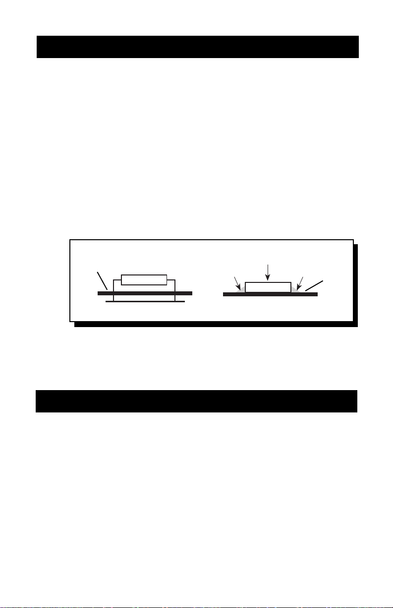
◆ DSM (Discrete Surface Mount) Technology
The
DSM
(Discrete Surface Mount) manufacturing process combines
the advantages of both discrete components and integrated circuitry.
Rockford Fosgate is the only American amplifier manufacturer to have
invested millions into this process. DSM components differ from
conventional discrete components in different ways. They are more
compact, more rugged, and they efficiently dissipate generated heat.
Using them wherever appropriate allows the advantages associated
with discrete circuitry to be retained while also providing room for
both highly advanced processing features and generous PC board
copper paths where needed. Their short lead-out structures allow
maximum audio performance and highest signal-to-noise ratios to be
obtained in amplifiers of desirable package size without resorting to
“amplifier-on-a-chip” shortcuts. These advantages are shown below
in Figure 1.
Figure 1
PC
Board
Thru-Hole Surface Mount
THE RESULT: Fewer connections, improved reliability, shorter signal
paths, superior signal-to-noise ratio and awesome sonic performance.
Solder
Component
Solder
PC
Board
◆ NOMAD (NOn-Multiplying Advanced Decision)
All Rockford Fosgate amplifiers use an
maximize safe output power under all operating conditions. The
innovative
is the most sophisticated version of this technique ever used, bringing
previously unavailable levels of accuracy, stability, temperature
immunity and reliability to this critical process. NOMAD makes
advanced decisions based on device voltages to precisely control the
awesome levels of current available in the output MOSFETs to safe
values – but only when absolutely needed.
NOMAD
(NOn-Multiplying Advanced Decision) system
analog computer process
to
THE RESULT: Extremely fast protection system that always protects
the amplifier and never degrades the sound.
– 3 –
Page 7

◆ High Level Inputs
The high level inputs on the Rockford Fosgate amplifiers convert the
speaker line outputs (high level) to preamp line inputs (low level).
This allows amplifier compatibility with a variety of source units as
well as the ability to integrate into factory systems without the need
for external adapters.
THE RESULT: Allows compatibility with factory and aftermarket
source units.
◆ XCard Crossover
The 5.3x amplifiers utilize internal active crossovers. These crossovers have many performance advantages such as using discrete
components for exact frequency adjustments which are far superior
to potentiometers. Additionally, the XCard can be configured for
high-pass, low-pass and full range operation. With slight modification, many crossover frequencies and slope configurations can be
achieved.
THE RESULT: Increased system design flexibility with a precise
electronic crossover without the limitations of conventional potentiometer designs.
◆ Signal Switching Network
The Signal Switching Network allows the RCA input signals to be
distributed to the amplifier channels in many different configurations. Among the many possible configurations, one setting uses a
single RCA (L mono) to feed the subwoofer channel, thus simplifying
connections needed.
THE RESULT: Allows input signals to be distributed to amplifier
channels in many different configurations.
– 4 –
Page 8
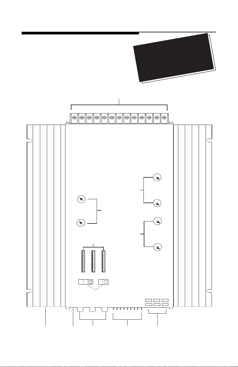
5.3X DESIGN FEATURES
Bias
CAUTION!
Do Not Adjust
Bias
CAUTION!
Any adjustment to
the Bias controls may damage
your amplifier and will void
your warranty.
2
Bias
CAUTION!
9
Do Not Adjust
Bias
9
Bias
CAUTION!
9
Do Not Adjust
6
8
1 7 3 4 5
– 5 –
Bias
Page 9

1. Dual Extruded Heatsinks
The dual extruded aluminum heatsinks of this RF amplifier
dissipate heat generated by the amplifier's circuitry.
2. Power/Speaker Barrier Strip
The barrier strip uses screw terminals that will accept #10 spade
lugs or bare speaker and power wire sizes from 10-18 AWG.
These gold-plated connectors are immune to corrosion that will
cause signal degradation.
3. RCA Input Jacks
The industry standard RCA jack provides an easy connection for
signal level input. They are gold-plated to resist the signal
degradation caused by corrosion.
4. High Level Inputs
The high level input connectors accept 1/8" spade lugs for the
connection of a source unit that has only speaker line (high level)
outputs.
5. Input Sensitivity Controls
The input level controls are preset for 500mV which will match
the output of most source units. They can be adjusted to match
output levels from a variety of source units.
6. Internal Crossovers
The built-in crossover cards are configurable for a multitude of
operating frequencies. The orientation of the card in its socket
determines its function of high-pass, low-pass or full range
operation.
7. LED Power Indicator
The LED gives a visual indication of the status of the amplifier,
lighting when the unit is turned on.
8. Signal Input Switches
These switches allow the input signals to be distributed to the
outputs in many different configurations.
9. Bias Controls
The Bias controls are preset at the factory and are not user
adjustable. CAUTION! ANY ADJUSTMENT TO THE BIAS
CONTROLS WILL VOID YOUR WARRANTY!
– 6 –
Page 10

INSTALLATION CONSIDERATIONS
The following is a list of tools you will need for installing the amplifier:
Wire Cutters #2 Phillips Screwdriver
Wire Strippers Assorted wire connectors
Wire Crimpers Battery Post Wrench
Voltmeter Electric Hand Drill with assorted bits
This section focuses on some of the vehicle considerations for
installing your new amplifier. Checking your battery and present
sound system, as well as pre-planning your system layout and best
wiring routes will save installation time. When deciding on the layout
of your new system, be sure that each component will be easily
accessible for making adjustments.
Before beginning any installation, be sure to follow these simple rules:
1. Be sure to carefully read and understand the instructions before
attempting to install the amplifier.
2. For safety, disconnect the negative lead from the battery prior to
beginning the installation.
3. For easier assembly, we suggest you run all wires prior to
mounting your amplifier in place.
4. Route all of the RCA cables close together and away from any high
current wires.
5. Use high quality connectors for a reliable installation and to
minimize signal or power loss.
6. Think before you drill! Be careful not to cut or drill into gas tanks,
fuel lines, brake or hydraulic lines, vacuum lines or electrical
wiring when working on any vehicle.
7. Never run wires underneath the vehicle. Running the wires inside
the vehicle provides the best protection.
8. Avoid running wires over or through sharp edges. Use rubber or
plastic grommets to protect any wires routed through metal,
especially the firewall.
9. ALWAYS protect the battery and electrical system from damage
with proper fusing. Install a fuseholder and appropriate fuse on
the +12V power wire within 18” (45.7 cm) of the battery terminal.
10. When grounding to the chassis of the vehicle, scrape all paint
from the metal to ensure a good, clean ground connection.
Grounding connections should be as short as possible and always
be connected to metal that is welded to the main body, or chassis,
of the vehicle.
– 7 –
Page 11

MOUNTING LOCATION
The mounting location and position of your amplifier will have a
great effect on its ability to dissipate the heat generated during normal
operation. The design of our aluminum heatsink serves to easily
dissipate the heat generated over a wide range of operating conditions. However, to maximize the performance of your amplifier, care
should be taken to ensure adequate ventilation.
Trunk Mounting
Mounting the amplifier vertically on a surface with the fin grooves
running up and down will provide the best cooling of the amplifier.
Mounting the amplifier on the floor of the trunk will work but
provides less cooling capability than vertical mounting.
Mounting the amplifier upside down to the rear deck of the trunk will
not provide proper cooling and will severely affect the performance
of the amplifier and is strongly
Passenger Compartment Mounting
Mounting the amplifier in the passenger compartment will work as
long as you provide a sufficient amount of air for the amplifier to cool
itself. If you are going to mount the amplifier under the seat of the
vehicle, you must have at least 1" (2.54cm) of air gap around the
amplifier's heatsink.
not
recommended.
Mounting the amplifier with less than 1" (2.54cm) of air gap around
the amplifier's heatsink in the passenger compartment will not
provide proper cooling and will severely affect the performance of
the amplifier and is strongly
not
recommended.
Engine Compartment Mounting
Rockford Fosgate amplifiers should
compartment. Not only will this void your warranty but could create
an embarrassing situation caused by the ridicule from your friends.
– 8 –
never
be mounted in the engine
Page 12

BATTERY AND CHARGING
Amplifiers will put an increased load on the vehicle's battery and
charging system. We recommend checking your alternator and
battery condition to ensure that the electrical system has enough
capacity to handle the increased load of your stereo system. Stock
electrical systems which are in good condition should be able to
handle the extra load of any Rockford amplifier without problems,
although battery and alternator life can be reduced slightly. To
maximize the performance of your Rockford Fosgate amplifier, we
suggest the use of a heavy duty battery and an energy storage
capacitor.
WIRING THE SYSTEM
CAUTION:
cables, antenna, power leads, sensitive equipment or harnesses. The
power wires carry substantial current and could induce noise into
the audio system.
• For safety, disconnect the negative lead from the battery prior to
beginning the installation.
1. Remove the cover and configure the internal XCard crossovers
prior to installation. Refer to “Using the XCard” (page 13) for
further information.
2. Plan the wire routing. Take care when running signal level RCA
cables to keep them close together but isolated from the amplifier's
power cables and any high power auto accessories, especially
electric motors. This is done to prevent coupling the noise from
radiated electrical fields into the audio signal. When feeding the
wires through the firewall or any metal barrier, protect them with
plastic or rubber grommets to prevent short circuits. Leave the
wires long at this point to adjust for a precise fit at a later time.
3. Prepare the Power cable for attachment to the amplifier by
stripping 1/2" of insulation from the end of the wire. Insert the
bared wire into the B+ terminal and tighten the set screw to secure
the cable in place.
NOTE: The B+ cable MUST be fused 18" or less from the vehicle's
battery. Install the fuseholder under the hood and prepare the
cable ends as stated above. Connections should be water tight.
Avoid running power wires near the low level input
– 9 –
Page 13

Trim the power cable within 18" of the battery and
strip 1/2" of insulation from the end of the wire.
Cut the wire loop that is attached to the fuseholder
in half and splice the fuse into the power line
using appropriate inline connectors. Use the
section of cable that was trimmed earlier and
connect it to the other end of the fuseholder.
4. Strip 1/2" from the battery end of the power cable
and crimp a large ring terminal to the cable. Use the ring terminal
to connect to the battery positive terminal. Do not install the fuse
at this time.
5. Prepare the Ground cable for attachment to the amplifier by
stripping 1/2" of insulation from the end of the wire. Insert the bared
wire into the GND terminal and tighten the set screw to secure the
cable in place. Prepare the chassis ground by scraping any paint
from the metal surface and thoroughly clean the area of all dirt and
grease. Strip the other end of the wire and attach a ring connector.
Fasten the cable to the chassis using a non-anodized screw and a
star washer.
6. Prepare the REM turn-on wire for connection to the amplifier by
stripping 1/2" of insulation from the wire end. Insert the bared
wire into the REM terminal and tighten the set screw to secure the
cable into place. Connect the other end of the REM wire to a
switched 12 volt positive source. The switched voltage is usually
taken from the source unit's auto antenna or the accessory lead.
If the source unit does not have these outputs available, the
recommended solution is to wire a mechanical switch in line with
a 12 volt source to activate the amplifier.
X
Cut
here
7. Securely mount the amplifier to the vehicle or amp rack. Be
careful not to mount the amplifier on cardboard or plastic panels.
Doing so may enable the screws to pull out from the panel due to
road vibration or sudden vehicle stops.
8. Connect the source signal to the amplifier by plugging the RCA
cables/high level inputs into the input jacks at the amplifier.
9. Connect the speakers. Strip the speaker wires 1/2" and insert into
the speaker terminal and tighten the set screw to secure into
place. Be sure to maintain proper speaker polarity.
DO NOT
chassis ground any of the speaker leads as unstable operation
may result.
10. Perform a final check of the completed system wiring to ensure
that all connections are accurate. Check all power and ground
connections for frayed wires and loose connections which could
cause problems.
– 10 –
Page 14

USING PASSIVE CROSSOVERS
A passive crossover is a circuit that uses capacitors and/or coils and is
placed on speaker leads between the amplifier and speaker. The
crossover delegates a specific range of frequencies to the speaker for
optimum driver performance. A crossover network can perform one of
three functions: High-Pass (capacitors), Low-Pass (inductors or coils)
and Bandpass (combination of capacitor and coil).
The most commonly used passive crossover networks are 6dB/octave
systems. These are easy to construct and require one component per
filter. Placing this filter in series with the circuit will reduce power to
the speaker by 6dB/octave above or below the crossover point
depending on whether it is a high-pass or low-pass filter. More
complex systems such as 12dB/octave or 18dB/octave can cause
impedance problems if not professionally designed.
Passive crossovers are directly dependent upon the speaker's impedance and component value for accuracy. When passive crossover
components are used in multiple speaker systems, the crossover's
effect on the overall impedance should be taken into consideration
along with the speaker's impedance when determining amplifier
loads.
CAUTION: The Rockford Fosgate amplifiers are not recom-
mended for impedance loads below 2Ω stereo and 4Ω bridged
(mono) loads.
a
O
p
d
e
v
r
a
a
n
t
c
i
e
o
d
n
– 11 –
Page 15
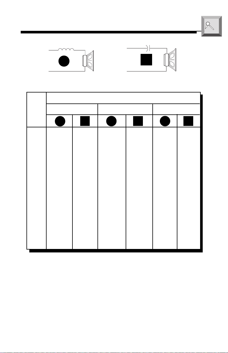
TABLE OF CROSSOVER COMPONENT VALUES
a
O
p
d
e
v
r
a
a
n
t
c
i
e
o
d
n
C
C
8 OHMS
L C
L
6 dB/Octave Low-Pass
Freq.
Hertz
2 OHMS
L
6 dB/Octave High-Pass
Speaker Impedance
4 OHMS
C L
80 4.1mH 1000µF 8.2mH 500µF 16mH 250µF
100 3.1mH 800µF 6.2mH 400µF 12mH 200µF
130 2.4mH 600µF 4.7mH 300µF 10mH 150µF
200 1.6mH 400µF 3.3mH 200µF 6.8mH 100µF
260 1.2mH 300µF 2.4mH 150µF 4.7mH 75µF
400 .8mH 200µF 1.6mH 100µF 3.3mH 50µF
600 .5mH 136µF 1.0mH 68µF 2.0mH 33µF
800 .41mH 100µF .82mH 50µF 1.6mH 26µF
1000 .31mH 78µF .62mH 39µF 1.2mH 20µF
1200 .25mH 66µF .51mH 33µF 1.0mH 16µF
1800 .16mH 44µF .33mH 22µF .68mH 10µF
4000 .08mH 20µF .16mH 10µF .33mH 5µF
6000 51µH14µF .10mH 6.8µF .20mH 3.3µF
9000 34µH 9.5µF68µH 4.7µF .15mH 2.2µF
12000 25µH 6.6µF51µH 3.3µF 100µH 1.6µF
6 dB/Octave High-Pass and Low-Pass Filters
L = Low-Pass (Inductor)
C = High-Pass (Capacitor)
For more information, see your Authorized Rockford Fosgate Dealer.
– 12 –
Page 16
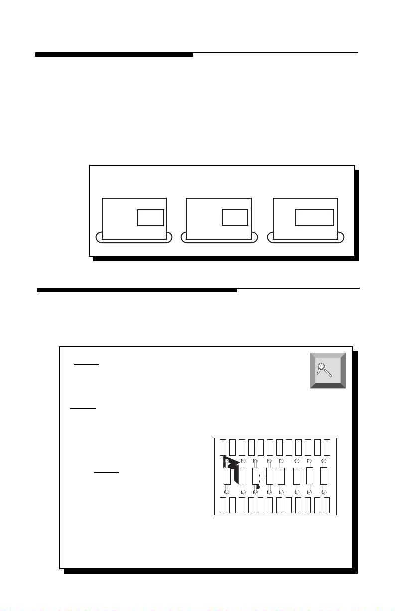
USING THE XCARD
The crossover functions are controlled through the use of an XCard
and can be set for high-pass, low-pass or full range operation. Each
crossover card has two faces: one face operates Full Range, the other
has arrows to indicate the edge for selecting HP (high-pass) or LP (lowpass) operation. Orient the card with the desired operating edge,
indicated by the arrow, toward the socket terminals inside the ampli-
fier. Firmly, but carefully, plug the card into the socket.
Low-Pass Full RangeHigh-Pass
➝
LP
➝
HP
➝
HP
LP
CUSTOMIZING THE XCARD
The crossover point can be altered by changing the 4 resistor values.
Use the following formula to select the appropriate resistor value to
be placed on the XCard.
3386
7234
The actual formula is:
R =
= R (in kΩ) for .047µf cap
f
o
= R (in kΩ) for .022µf cap
f
o
1
2πfoc
C1
➝
R1
Crossover Card
High Pass
C1
C2
R2
Low Pass
Full Range
FULL
R1
FULL
C2
↕
a
O
p
d
e
v
r
a
a
n
t
c
i
e
o
d
n
R2
Where: R = Ω
fo = desired crossover frequency
c = capacitor in farads
ex: .047 x 10-6 for .047mf cap
– 13 –
Page 17

RESISTOR CHART
Our tests have shown that using 0.047µf capacitors for frequencies below 100Hz, and
0.022µf capacitors for frequencies above 100Hz, result in more linear crossover
control. Refer to the Specifications page to determine the capacitor value of each
supplied XCard.
Butterworth Alignment Q = .707
1% resistors used with 0.047µF caps
Frequency R1 R2
20Hz 169k
25Hz 133kΩ 133kΩ
30Hz 110kΩ 110kΩ
35Hz 95.3kΩ 95.3kΩ
40Hz 84.5kΩ 84.5kΩ
45Hz 75kΩ 75kΩ
50Hz 68.1kΩ 68.1kΩ
55Hz 61.9kΩ 61.9kΩ
60Hz 56.2kΩ 56.2kΩ
65Hz 52.3kΩ 52.3kΩ
70Hz 48.7kΩ 48.7kΩ
75Hz 45.3kΩ 45.3kΩ
80Hz 42.2kΩ 42.2kΩ
85Hz 40.2kΩ 40.2kΩ
90Hz 37.4kΩ 37.4kΩ
200Hz 16.9kΩ 16.9kΩ
300Hz 11.3kΩ 11.3kΩ
400Hz 8.45kΩ 8.45kΩ
500Hz 6.65kΩ 6.65kΩ
600Hz 5.62kΩ 5.62kΩ
700Hz 4.75kΩ 4.75kΩ
800Hz 4.22kΩ 4.22kΩ
900Hz 3.74kΩ 3.74kΩ
1kHz 3.40kΩ 3.40kΩ
1.2kHz 2.80kΩ 2.80kΩ
2kHz 1.69kΩ 1.69kΩ
3kHz 1.10kΩ 1.10kΩ
4kHz 845Ω 845Ω
5kHz 665Ω 665Ω
6kHz 562Ω 562Ω
7kHz 487Ω 487Ω
8kHz 422Ω 422Ω
Ω 169kΩ
Butterworth Alignment Q = .707
1% resistors used with 0.022µF caps
Frequency R1 R2
20Hz 357kΩ 357kΩ
25Hz 287kΩ 287kΩ
30Hz 237kΩ 237kΩ
35Hz 205kΩ 205kΩ
40Hz 178kΩ 178kΩ
45Hz 162kΩ 162kΩ
50Hz 143kΩ 143kΩ
55Hz 130kΩ 130kΩ
60Hz 121kΩ 121kΩ
65Hz 110kΩ 110kΩ
70Hz 102kΩ 102kΩ
75Hz 95.3kΩ 95.3kΩ
80Hz 90.9kΩ 90.9kΩ
85Hz 84.5kΩ 84.5kΩ
90Hz 80.6kΩ 80.6kΩ
200Hz 35.7k
300Hz 23.7kΩ 23.7kΩ
400Hz 17.8kΩ 17.8kΩ
500Hz 14.3kΩ 14.3kΩ
600Hz 12.1kΩ 12.1kΩ
700Hz 10.2kΩ 10.2kΩ
800Hz 9.9kΩ 9.9kΩ
900Hz 8.6kΩ 8.6kΩ
1.0kHz 7.15kΩ 7.15kΩ
1.2kHz 6.04kΩ 6.04kΩ
2.0kHz 3.57kΩ 3.57kΩ
3.0kHz 2.37kΩ 2.37kΩ
4.0kHz 1.76kΩ 1.76kΩ
5.0kHz 1.43kΩ 1.43kΩ
6.0kHz 1.21kΩ 1.21kΩ
7.0kHz 1.02kΩ 1.02kΩ
8.0kHz 909Ω 909Ω
Ω 35.7kΩ
a
O
p
d
e
v
r
a
a
n
t
c
i
e
o
d
n
– 14 –
Page 18

XCARD ACCESS
The internal XCard crossover(s) are accessible by removing the top
cover from the amplifier. The XCard should be inserted with the filter
side (HP, LP or FULL RANGE) facing the metal contacts inside the
socket.
FULL
Bias
Bias
CAUTION!
Do Not Adjust
↕
Bias
Rear XCard
Front XCard
Subwoofer XCard
Bias
Do Not Adjust
➝
LP
HP
➝
CAUTION!
Low-Pass Full RangeHigh-Pass
HP
LP
➝
Bias
➝
Bias
CAUTION!
Do Not Adjust
• Remove six Allen Screws from cover with supplied Allen wrench (3/32")
• Insert XCard into socket with HP, LP, or FULL RANGE facing metal
contacts.
FACTORY DEFAULTS
Rear XCard = Full Range
Front XCard = Full Range
Subwoofer XCard = 80Hz LP
– 15 –
Page 19

USING THE SIGNAL SWITCHING NETWORK
The Signal Switching Network allows the RCA input signals to be
distributed to the outputs in many different configurations. The
orientation of
switches can be oriented in the following configurations.
Configuration #1
(Mono Sub Input)
both switches
configure the distribution pattern . The
SUB XCard
FRONT XCard
REAR XCard
Configuration #2
SUB XCard
FRONT XCard
REAR XCard
Configuration #3
SUB XCard
FRONT XCard
REAR XCard
Front inputs => Front outputs
Rear inputs => Rear outputs
Subwoofer (L Mono) input => Subwoofer outputs
Front inputs => Front outputs
Rear inputs => Rear outputs
Subwoofer inputs => Subwoofer outputs
Front inputs => Front outputs
Rear inputs => Rear outputs
Front & Rear inputs
summed
=> Subwoofer outputs
– 16 –
Factory
Default
Setting
Page 20

Configuration #4
(Mono Sub Input)
SUB XCard
FRONT XCard
REAR XCard
Configuration #5
SUB XCard
FRONT XCard
REAR XCard
Configuration #6
SUB XCard
FRONT XCard
REAR XCard
Front inputs => Front & Rear outputs
Subwoofer (L Mono) input => Subwoofer outputs
Front inputs => Front & Rear outputs
Subwoofer inputs => Subwoofer outputs
Front inputs => Front, Rear &
Subwoofer outputs
– 17 –
Page 21

Configuration #1
Front inputs => Front outputs
Rear inputs => Rear outputs
Subwoofer (L Mono) inputs => Subwoofer outputs
SUB XCard
FRONT XCard
REAR XCard
LED
LF
RF
AA
LR
RR
BB
L-Subwoofer
R-Subwoofer
+RF–
+LF–
High Level Inputs
+LR– +RR–GND
Front
Gain
(L Mono)
C
® ®
LF+
LF-
RF+
RF-
RR-
LR+ RR+
390 Watts Total Power
B+LR-
A A B B C
Rear
Sub
Gain
Gain
SUB
SUB
+
GNDREM
–
– 18 –
Page 22

Configuration #2
Front inputs => Front outputs
Rear inputs => Rear outputs
Subwoofer inputs => Subwoofer outputs
SUB XCard
FRONT XCard
REAR XCard
LED
LF
RF
AA
® ®
LF+
LF-
BB
RF+
LR
RR
L-Subwoofer
R-Subwoofer
C
RF-
C
+RF–
+LF–
High Level Inputs
RR-
LR+ RR+
+LR– +RR–GND
390 Watts Total Power
B+LR-
Front
Gain
A A B B C
Rear
Sub
Gain
Gain
SUB
SUB
+
GNDREM
–
– 19 –
Page 23

Configuration #3
Front inputs => Front outputs
Rear inputs => Rear outputs
Front & Rear inputs
SUB XCard
FRONT XCard
REAR XCard
summed
=> Subwoofer outputs
Factory
Default
Setting
LED
LF
RF
AA
® ®
LF+
LF-
BB
RF+
LR
RR
L-Subwoofer
R-Subwoofer
RF-
A A B B
+RF–
+LF–
High Level Inputs
RR-
LR+ RR+
+LR– +RR–GND
390 Watts Total Power
B+LR-
Front
Gain
GNDREM
Rear
Gain
SUB
+
A&B
Sub
Gain
SUB
–
– 20 –
Page 24

Configuration #4
(Mono Sub Input)
Front inputs => Front & Rear outputs
Subwoofer (L Mono) inputs => Subwoofer outputs
SUB XCard
FRONT XCard
REAR XCard
LED
LF
RF
LR
RR
L-Subwoofer
R-Subwoofer
+RF–
+LF–
High Level Inputs
+LR– +RR–GND
Front
Gain
AA
(L Mono)
C
® ®
LF+
LF-
RF+
RF-
RR-
LR+ RR+
390 Watts Total Power
B+LR-
A A A A C
Rear
Sub
Gain
Gain
SUB
SUB
+
GNDREM
–
– 21 –
Page 25

Configuration #5
Front inputs => Front & Rear outputs
Subwoofer inputs => Subwoofer outputs
SUB XCard
FRONT XCard
REAR XCard
LED
LF
RF
AA
® ®
LF+
LF-
RF+
LR
RR
L-Subwoofer
R-Subwoofer
RF-
C
C
+RF–
+LF–
High Level Inputs
RR-
LR+ RR+
+LR– +RR–GND
Front
390 Watts Total Power
B+LR-
Gain
A A A A C
Rear
Sub
Gain
Gain
SUB
SUB
+
GNDREM
–
– 22 –
Page 26

Configuration #6
Front inputs => Front, Rear &
Subwoofer outputs
SUB XCard
FRONT XCard
REAR XCard
LED
LF
RF
LR
RR
L-Subwoofer
R-Subwoofer
+RF–
+LF–
High Level Inputs
+LR– +RR–GND
Front
Gain
AA
® ®
LF+
LF-
RF+
RF-
RR-
LR+ RR+
390 Watts Total Power
B+LR-
A A A A A
Rear
Sub
Gain
Gain
SUB
SUB
+
GNDREM
–
– 23 –
Page 27

5.3X INSTALLATION
High Level Input – “Single Ended” Type
This configuration is used for source units that have “Single Ended” speaker
outputs. Only the “+” output is “hot,” whereas the “–” or “common” are
common grounded. To verify your source unit has these outputs, connect an
ohm meter across the “–” output and radio chassis for a reading of 0Ω.
I
® ®
N
S
T
A
L
L
A
T
I
O
N
DIM
PAUSE
L+
COMM
SEL
Front
Gain
R
TUNE
Rear
Sub
Gain
Gain
LED
AUD
DISC
FM
ST
AM
PWR
VOL
® ®
Front
Ch
RPTLD
RDM
CLOCK
ILLUM
AUTO
P.SCN LOUDDSPL
RDM
RPT
SCAN
D.SCN
1 2 3 4 5 6
Rear
R+
COMM
L+ R+
+RF–
L-Subwoofer
LF
RF
LR
R-Subwoofer
RR
Use “Configuration #6” of
Signal Switching Network
when using front inputs only
+LF–
High Level Inputs
+LR– +RR–GND
Use “Configuration #3” of Signal
Switching Network when using
front & rear inputs
• L+ and R+ Inputs are connected to corresponding “+” speaker outputs
• L– and R– Inputs are
not used
• GND Input is connected to “–” speaker outputs
• Configuration #6* is used with FRONT inputs to achieve Sub output
• Configuration #3* is used with FRONT & REAR inputs to achieve Sub output
* Refer to previous pages for
Signal Switching Network
configurations
CAUTION: Use 1/8" female connectors when using the high level inputs and DO NOT
solder wires directly to the connector
– 24 –
Page 28

High Level Input – “B.T.L.” Type
This configuration is used for source units that have “B.T.L.” speaker outputs
(Bridged Transformer Less
not
Bacon Tomato & Lettuce). Both “+” and “–”
outputs are considered “hot” or “floating.”
Factory Radio
I
® ®
N
S
T
A
L
L
A
T
I
O
N
LED
+
–
L-Subwoofer
LF
RF
LR
R-Subwoofer
RR
Use “Configuration #6” of
Signal Switching Network
when using front inputs only
100.7
Front
R–
R+
L–
L+ R–
+RF–
+LF–
High Level Inputs
Rear
+LR– +RR–GND
Use “Configuration #3” of
Signal Switching Network
when using front & rear inputs
^
v
L+
L–
R+
Rear
Gain
Sub
Gain
Front
Gain
• L+ and R+ Inputs are connected to corresponding “+” speaker outputs
• L– and R– Inputs are connected to corresponding “–” speaker outputs
• GND Input
is not used
unless noise problems arise
• Configuration #6* is used with FRONT inputs to achieve Sub output
• Configuration #3* is used with FRONT & REAR inputs to achieve Sub output
* Refer to previous pages for
Signal Switching Network
configurations
CAUTION: Use 1/8" female connectors when using the high level inputs and DO NOT
solder wires directly to the connector
– 25 –
Page 29

Power Connections
® ®
LF+
LF-
RF+
Less than 18"
3-Channel Operation
® ®
LF+
LF-
RF+
RF-
Connect to B+ of battery
with 30A fuse
RF-
LR+ RR+
LR+ RR+
RR-
Connect to remote
turn-on lead of
source unit
RR-
390 Watts Total Power
B+LR-
GNDREM
Connect to chassis
ground of vehicle
390 Watts Total Power
B+LR-
GNDREM
SUB
SUB
I
® ®
N
S
T
A
L
L
A
T
I
O
N
SUB
+
–
SUB
+
–
+
–
4Ω Min.
LEFT
• Front/Rear Gain Controls
• Sub Gain Control operates
–
4Ω Min.
RIGHT
set equally
independently
• Impedance Load for Left bridged channel should be
• Impedance Load for Right bridged channel should be
+
to balance left and right speakers
4Ω minimum
4Ω minimum
• Impedance Load for Sub bridged/mono channel should be
• Front/Rear XCard
set identically
as High-Pass, Low-Pass or Full Range
• Sub XCard can be set for High-Pass, Low-Pass or Full Range
– 26 –
+
4Ω Min.
4Ω minimum
–
Page 30

3-Channel Mono Operation
® ®
LF+
LF-
RF+
RF-
RR-
LR+ RR+
390 Watts Total Power
B+LR-
GNDREM
SUB
I
® ®
N
S
T
A
L
L
A
T
I
O
N
SUB
+
–
+
–
–
4Ω Min.
• Front/Rear Gain Controls
• Sub Gain Control operates
set equally
independently
• Impedance Load for Front bridged channel should be
• Impedance Load for Rear bridged channel should be
+
4Ω Min.
to balance the speakers
4Ω minimum
4Ω minimum
• Impedance Load for Sub bridged/mono channel should be
• Front/Rear XCard
set
as High-Pass, Low-Pass or Full Range
• Sub XCard can be set for High-Pass, Low-Pass or Full Range
5-Channel Operation
® ®
LF+
+
LF-
RF+
–
+
RF-
RR-
LR+ RR+
–
–
–
+
+
300 Watts Total Power
B+LR-
+
4Ω Min.
4Ω minimum
SUB
+
GNDREM
+
SUB
–
–
–
2Ω Min.
• Front/Rear/ Sub Gain Controls operate
• Impedance Load for Front/Rear channels should be
2Ω Min.
2Ω Min.
2Ω Min.
independently
2Ω minimum
• Impedance Load for Sub bridged/mono channel should be
• Front/Rear XCard
set
as High-Pass, Low-Pass or Full Range
• Sub XCard can be set for High-Pass, Low-Pass or Full Range
– 27 –
4Ω Min.
4Ω minimum
Page 31

SYSTEM DIAGRAMS
230 Watt System (rated @ 4 ohms)
Step #1
Upgrade the factory system with an RF5.3x amplifier and mono subwoofer.
Factory Radio
HP
Front XCard
LP
XCard
Subwoofer
+
–
100.7
^
v
HP
Rear XCard
High Level Input
Front
Factory
Speaker
80Hz-20kHz
12dB/octave HP
– 28 –
Front
Factory
Speaker
4Ω Woofer
20Hz-80Hz
12dB/octave LP
Page 32

230 Watt System (rated @ 4 ohms)
Step #2
Further upgrade the factory system by replacing the front factory speakers and
adding “rear fill” speakers.
Factory Radio
HP
Rear XCard
LP
Front XCard
XCard
Subwoofer
+
100.7
–
^
v
High Level Input
HP
80Hz-20kHz
12dB/octave HP
Front
Rear
20Hz-80Hz
12dB/octave LP
– 29 –
4Ω Woofer
Front
Rear
80Hz-20kHz
12dB/octave HP
Page 33

350 Watt System (rated @ 4 ohms)
Step #3
Replace the factory source unit with an RFX-8030, adding a 4.6x amplifier and
more subwoofers.
SKIP
AUD
PWR
VOL
®®
D.SCN DIM
RFX-8030
CLOCK AUTO
P.SCN LOUDDSPL
ILLUM
DIGITAL AUDIO
RDMRPTSCAN PAUSE
564321
MON
SEL
COMPACT
TUNE
LP
LP
Rear XCard
Front XCard
LP
XCard
Subwoofer
HP
Front XCard
Front
80Hz-20kHz
12dB/octave HP
Rear
HP
Rear XCard
Front
80Hz-20kHz
12dB/octave HP
Rear
4Ω Woofer
4Ω Woofer 4Ω Woofer
20Hz-80Hz
12dB/octave LP
– 30 –
Page 34

410 Watt System (rated @ 4 ohms)
Step #4
Complete the system by adding a CD changer, midbass speakers, and
dedicating an RF-2.6x for “rear fill.”
SKIP
P.SCN LOUDDSPL
ILLUM
RDMRPTSCAN PAUSE
564321
COMPACT
DIGITAL AUDIO
Sub
MON
SEL
TUNE
20Hz-80Hz
12dB/octave LP
LP
LP
Rear XCard
Front XCard
Front
AUD
PWR
VOL
RFX-8030
®®
CLOCK AUTO
D.SCN DIM
Rear
®
®
RFX-8601
disc
changer
6
LP
XCard
Subwoofer
HP
Front XCard
Front
80Hz-20kHz
12dB/octave HP
Midbass
80Hz-400Hz
12dB/octave BP
80Hz-400Hz
12dB/octave BP
Rear XCard
Front
80Hz-20kHz
12dB/octave HP
Midbass
Rear
HP
7.342
80Hz-20kHz
12dB/octave HP
4Ω Woofer
HP
Rear XCard
Rear
4Ω Woofer 4Ω Woofer
20Hz-80Hz
12dB/octave LP
– 31 –
Page 35

TROUBLESHOOTING
Symptom Diagnosis Remedy
TROUBLE-
S
H
O
O
T
I
N
G
Amplifier does not
turn on
(Power LED is off)
Amplifier has no
sound
(Power LED is on)
Voltage applied to the
REM terminal of the
amplifier is not between
10.5 and 15.5 volts or
there is no voltage
present.
Voltage to the B+ terminal of the amplifier is
not between 10.5 and
15.5 volts or there is no
voltage present.
Amplifier is not properly grounded.
RCA Input from source
unit is not connected or
not functioning properly.
XCard is missing or not
placed properly in crossover slots.
Check the alternator, battery, fuse, and wiring and
repair as necessary. If the
voltage is above 15.5 volts,
have the electrical system
inspected by an authorized
car service center.
Check the alternator, battery, fuse, and wiring and
repair as necessary. If the
voltage is above 15.5 volts,
have the electrical system
inspected by an authorized
car service center.
Check wiring and repair as
necessary.
Check connections, substitute with known working
source and cables and repair
or replace as necessary.
Check XCard position and
repair or replace as necessary.
Speaker leads are shorted
to each other or to the
chassis of the vehicle.
Speakers are defective.
– 32 –
Disconnect existing speakers
and test with known working
speakers and wires. If amplifier plays, check and repair
wiring and installation of
speakers as necessary.
Disconnect existing speakers and test with known
working speakers. If amplifier plays, check and repair
speakers as necessary.
Page 36

Symptom Diagnosis Remedy
TROUBLE-
S
H
O
O
T
I
N
G
Speaker Output
Low or Distorted
No Output on
Front, Rear or Sub
Channels
Low Output on
Sub Channel
Input gain signal for
amplifier is incorrectly
set.
Source unit output too
low or source unit has
no output.
XCard is missing or not
placed properly in crossover slots.
Low battery voltage or
large voltage drops to
the amplifier under load.
Signal Input Switches not
configured properly.
XCard(s) missing or not
placed properly in crossover slot.
Signal Input Switches do
not configure Sub Channel for single RCA input.
Readjust input gains of
amplifier.
Check system with known
working source and repair
or replace original source
as needed.
Check XCard position and
repair or replace as necessary.
Check the alternator, battery, fuse, and power and
ground wiring. Repair as
necessary.
Check Signal Input
Switches and reconfigure
as necessary.
Check XCard position(s)
and repair or replace as
necessary.
Check Signal Input
Switches and reconfigure
as necessary.
Amplifier Noise
(Turn-on Pop)
Voltage spike from output of preceding component is entering amplifier
through input signal.
Voltage spike from remote turn-on lead is entering through REM input terminal.
– 33 –
Disconnect input signal to
amplifier and turn amplifier
on and off. If noise is eliminated, connect REM lead of
amplifier to source unit with
a delay turn-on module.
Use a different 12 volt
source for REM lead of amplifier (i.e., battery direct). If
noise is eliminated, use a
relay to isolate amplifier
from noisy turn-on output.
Page 37

Symptom Diagnosis Remedy
TROUBLE-
S
H
O
O
T
I
N
G
Engine Noise
Noise is radiating into
RCA signal cable.
Bad component in the signal chain.
Noise is radiating into
speaker cables.
Multiple grounds in the
audio system.
Check connections, and
run the RCA cables on a
different route away from
sources of high current.
Check connections, and bypass additional components
(crossovers and equalizers)
between the source unit and
the amplifier. Connect one
component at a time to determine the culprit. Repair
or replace components as
necessary.
Disconnect existing speakers and connect a test
speaker to the output terminals of the amplifier. If
noise is gone, reroute the
speaker cables away from
sources of high voltage.
Check ground connections
and connect amplifiers, signal processors, and other
components to a central
location or try a different
grounding point on the
chassis.
Ground loop between
source unit and antenna.
Check connections and
disconnect antenna from
source unit. If noise is gone,
install an antenna ground
loop isolator.
Engine noise with
high level inputs
No reference ground
Connect GND terminal of
high level input to chassis
of source unit.
• If noise persists, see your Authorized Rockford Fosgate Dealer.
– 34 –
Page 38

DYNAMIC POWER MEASUREMENTS
About the Dynamic Power Measurements
The Audio Graph PowerCube is a test instrument used to measure the
output of an amplifier in accordance with IHF-202 industry standards. The
IHF-202 standard is a dynamic power measurement and was developed
as a means of measuring power in a manner that best represents the Real
World operation of an amplifier. Many manufacturers, including Rockford
Fosgate, at times will measure amplifier power into a fixed resistor (4 ohm,
2 ohm). While this method is useful in some types of evaluation and
testing, it is not representative of an amplifier that is connected to a speaker
and playing music.
Music
Music is dynamic; the sound waves are complex and constantly changing.
In order to simulate this, the IHF-202 standard calls for the input signal to
the amplifier to be a 1kHz bursted tone. This signal is input (on for 20
milliseconds) and reduced 20dB for 480 milliseconds. The signal is
gradually increased in level until the amplifier's output exceeds 1% Total
Harmonic Distortion (THD). At 1% distortion becomes audible, therefore,
any power produced above that level is considered
manufacturers represent their amplifiers' output power in excess of 10%
distortion. They use many names for this measurement, such as Total
Maximum Power or Maximum Output Power. This is not indicative of the
actual usable output power
.
unusable
. Many
Listening to Loudspeakers - Not Resistors
A loudspeaker is not a resistor. A resistor's value (resistance measured in
ohms) is fixed. A loudspeaker's impedance is dynamic. It is constantly
changing in value, dependent upon the frequency of the input signal.
Therefore, measuring power with the amplifier loaded into a 4 ohm
resistor is not the same as measuring power with the amplifier connected
to a 4 ohm speaker. Most people do not listen to music through a resistor.
A 4 ohm speaker may experience a drop in impedance 4-6 times lower than
its nominal (printed) impedance. A speaker will also create phase shifts in
the signal that is passed through it. These phase shifts happen because a
speaker is an inductor (voice coil) and a capacitor (compliance of the
surround/spider), as well as a resistor (voice coil wire).
To simulate a speaker the Audio Graph PowerCube measures output
power into 20 different loads. It tests at 8 ohms, 4 ohms, 2 ohms and 1
ohm. Each of these impedances is also tested at –60°, –30°, 0°, +30° and
+60° phase angles. These different impedances and phase angles represent the shifts in impedance and phase that can occur in a typical
loudspeaker.
– 35 –
Page 39

Information Cubed
The data acquired in the testing procedure is then graphed in the form
of a 3-dimensional cube, hence the name PowerCube.
The
Phase Angle
Voltage
is presented on the vertical axis and the
displayed on the Z axis.
is expressed on the horizontal axis, the
Impedance
Output Power,
in watts, is listed on the left
Output
is
hand side for each impedance at each phase angle.
Audio Graph – The PowerCube™
MODEL BEING
TESTED
Amplifier:
PUNCH 200.
Serial No:
Owner :
ROCKFORD CORPORATION
85 W
8Ω –60°
*
84 W
–30°
84 W
0°
84 W
30°
86 W
60°
162 W
4Ω –60°
*
157 W
–30°
156 W
0°
157 W
30°
162 W
60°
273 W
2Ω –60°
*
IMPEDANCE
258 W
–30°
251 W
0°
256 W
30°
271 W
60°
390 W
1Ω –60°
*
356 W
–30°
346 W
0°
352 W
30°
390 W
60°
VOLTAGE FROM
BATTERY
2
14.4V x 2
POWER
IN
WATTS
{
–60° (Cap)
• Example of a Punch 200x2 PowerCube
MONO = BRIDGED MONO
0°
{
PHASE ANGLES
x2 = STEREO
Rated Power : 100 W @ 4 Ohms
2Ω
1Ω
(Ind) +60°
{
Impedance
50V
30V
10V
OUTPUT VOLTAGE
8Ω
4Ω
What is an Amplifier?
An amplifier by definition is a voltage generating device, recreating
the signal which is input to it identically but with increased volume.
It will be connected to a reactive load (the speaker). The impedance
of this load and phase of the signal passing through the load will vary,
dependent upon the frequency of the input signal (music).
Therefore, a perfect amplifier will be able to maintain the same output
voltage regardless of load characteristics and will not alter the signal
it is reproducing. A perfect amplifier when measured by the Audio
Graph PowerCube would present data that forms a perfect cube.
Unfortunately, amplifiers are not perfect. The laws of physics generally prevent it. A great amplifier is about the best one can hope to
attain.
As you can see by the PowerCube and as you will experience by
listening, your Punch amplifier is a GREAT AMPLIFIER!
– 36 –
Page 40

5.3X SPECIFICATIONS
Front/Rear Sub
Channels Channel
Dynamic Power Rating (IHF 202 Standard)
Measured at 14.4 Voltage
Per channel into a 4Ω Load 40 Watts x 4
Per channel into a 2Ω Load 65 Watts x 4
Bridged Mono into a 4Ω Load 130 Watts x 2 130 Watts x 1
Continuous Power Rating (Competition Standard)
Measured at 14.4 Battery Voltage
RMS continuous power per channel, 30 Watts x 4
all channels driven into a 4Ω load from
20 to 20,000 Hz, with less than 0.30%
Total Harmonic Distortion (THD)
RMS continuous power per channel, 55 Watts x 4
all channels driven into a 2Ω load from
20 to 20,000 Hz, with less than 0.50%
Total Harmonic Distortion (THD)
RMS continuous power bridged/mono 110 Watts x 2 110 Watts x 1
into a 4Ω load from 20 to 20,000 Hz
with less than 0.50% Total Harmonic Distortion (THD)
Signal-to-Noise Ratio >100dB (A-weighted)
Bandwidth 10 Hz to 250kHz ± 3dB
Damping Factor @ 4Ω >200
Frequency Response 20 Hz to 20 kHz ± 0.5dB
Slew Rate 30Vµs
IM Distortion (IHF) <0.05%
Input Impedance 20,000 ohms
Input Voltage Variable from 325mV to 5.5volts
(Low level in-RCA)
Variable from 850mV to 15 volts
(High level in-BTL)
Variable from 425mV to 7.5 volts
(High level in – Single Ended)
– 37 –
Page 41

Protection NOMAD - Internal analog-computer out-
put protection circuitry limits power in case
of overload. Thermal switch shuts down
the amplifier in case of overheating.
Factory Default Crossover Front XCard = 80Hz (0.047µf)
Rear XCard = 80Hz (0.047µf)
Sub XCard = 80Hz (0.047µf)
Crossover Slope 12dB/octave Butterworth
Battery Fusing Ratings 30 Amps
(External to Amplifier)
Fuse Type ATC
5
Dimensions 10
⁄8”W x 111⁄2L x 2"H
(26.9cm) x (29.21cm) x (5.08cm)
Specifications subject to change without notice.
– 38 –
Page 42

LIMITED WARRANTY INFORMATION
Rockford Corporation offers a limited warranty on Rockford Fosgate products on the
following terms:
• Length of Warranty
3 years on electronics 90 days on electronic B-stock (receipt required)
2 years on source units 30 days on speaker B-stock (receipt required)
1 year on speakers
• What is Covered
This warranty applies only to Rockford Fosgate products sold to consumers by
Authorized Rockford Fosgate Dealers in the United States of America or its
possessions. Product purchased by consumers from an Authorized Rockford
Fosgate Dealer in another country are covered only by that country’s Distributor
and not by Rockford Corporation.
• Who is Covered
This warranty covers only the original purchaser of Rockford product purchased
from an Authorized Rockford Fosgate Dealer in the United States. In order to
receive service, the purchaser must provide Rockford with a copy of the receipt
stating the customer name, dealer name, product purchased and date of purchase.
• Products found to be defective during the warranty period will be repaired or
replaced (with a product deemed to be equivalent) at Rockford's discretion.
• What is Not Covered
1. Damage caused by accident, abuse, improper operations, water, theft
2. Any cost or expense related to the removal or reinstallation of product
3. Service performed by anyone other than Rockford or an Authorized Rockford
Fosgate Service Center
4. Any product which has had the serial number defaced, altered, or removed
5. Subsequent damage to other components
6. Any product purchased outside the U.S.
7. Any product not purchased from an Authorized Rockford Fosgate Dealer
• Limit on Implied Warranties
Any implied warranties including warranties of fitness for use and merchantability
are limited in duration to the period of the express warranty set forth above. Some
states do not allow limitations on the length of an implied warranty, so this
limitation may not apply. No person is authorized to assume for Rockford Fosgate
any other liability in connection with the sale of the product.
• How to Obtain Service
Please call 1-800-669-9899 for Rockford Customer Service. You must obtain an
RA# (Return Authorization number) to return any product to Rockford Fosgate. You
are responsible for shipment of product to Rockford.
Ship to: Electronics
Rockford Corporation
Warranty Repair Department
2055 E. 5th Street
Tempe, AZ 85281
RA#:_________________
Ship to: Speakers
Rockford Acoustic Design
(Receiving-speakers)
609 Myrtle N.W.
Grand Rapids, MI 49504
RA#:_________________
– 39 –
Page 43

NTERNATIONAL
I
INFORMATION
– 40 –
Page 44

Por favor, lea las instrucciones siguientes para la instalación de este producto.
El hecho de proceder al montaje sin haber leido estas instrucciones, podria
resultar fatal para usted o para el vehiculo.
INTRODUCCIÓN
El RFX 5.3x es un amplificador de 5 canales estéreo y un canal
puenteado en mono para acomodarse a los diseños de sistemas de “un
solo amplificador” con un precio competitivo. Como este manual
proporciona información sobre las características, instalación y
funcionamiento del amplifiador Rockford Fosgate 5.3x, le sugerimos
que lo guarde para futuras referencias.
Recomendamos que contacte con un distribuidor autorizado por Rockford Fosgate para la instalación de su nuevo Amplificador. Sin embargo,
si decide instalar este amplificador usted mismo, asegurese de leer todo
el manual antes de empezar el montaje.
UTILIZACION DEL CIRCUITO DE CONMUT ACION
SEÑAL
DE
El circuito de conmutación de señal permite distribuir las entradas RCA
a las salidas de varias diferentes maneras. La orientación de ambos
conmutadores configura la distribución de señal. Los conmutadores
pueden ser posicionados en las siguientes configuraciones.
Configuración n°1
(Entrada de Subwoofer en mono)
Entrada Frontales => Salidas Frontales
SUB XCard
FRONT XCard
REAR XCard
Entrada Posteriores => Salidas Posteriores
Entradas de Subwoofer => Salidas de Subwoofer
(Izquierda Mono)
Configuración n°2
Entrada Frontales => Salidas Frontales
SUB XCard
FRONT XCard
REAR XCard
Entrada Posteriores => Salidas Posteriores
Entradas de Subwoofer => Salidas de Subwoofer
– 41 –
Page 45

Configuración n°3
Entrada Frontales => Salidas Frontales
SUB XCard
FRONT XCard
REAR XCard
Entrada Posteriores => Salidas Posteriores
Entradas Frontales y => Salidas de Subwoofer
Configuración n°4
(Entrada de Subwoofer en mono)
ESPAÑOL
Posteriores
Configuración
Standard de
Fábrica
SUB XCard
FRONT XCard
REAR XCard
Configuración n°5
SUB XCard
FRONT XCard
REAR XCard
Configuración n°6
SUB XCard
FRONT XCard
REAR XCard
Entrada Frontales => Salidas Frontales y
Posteriores
Entradas de Subwoofer => Salidas de Subwoofer
(Izquierda Mono)
Entrada Frontales => Salidas Frontales y
Posteriores
Entradas de Subwoofer => Salidas de Subwoofer
Entrada Frontales => Salidas Frontales,
Posteriores y Subwoofer
– 42 –
Page 46

Veuillez lire les instructions suivantes relatives à l'installation de ces produits.
Ne pas suivre ces instructions pourrait entrainer des dommages à vous-même
ou à votre véhicule.
INTRODUCTION
Le RF5.3x est un amplifiacteur à 5 canaux avec quatre canaux stéréo et
un canal mono. Ce manuel contient des informations importantes sur
l'installation et le fontionnement de l'appareil. Nous vous conseillons
de bien le conserver.
Nous vous recommandons vivement de faire installer votre nouvel
amplificateur Rockford Fosgate auprès d'un installateur agréé Rockford
Fosgate. Néanmoins, si vous décidez d'installer vous-méme votre
amplificateur, assurez-vous e lire l'entièreté e ce manuel avant de
commencer.
UTILISATION DU RÉSEAU DE COMMUTATION
SIGNAL
DU
Le réseau de commutation du signal permet au signal provenant des
RCA e'entrée d'être distribué vers les sorties dans de multiple configurations. L'orientation des deux commutateurs configure la distribu-
tion de signal. Les commutateurs peuvent être orientés afin d'obtenir
les configurations suivantes:
Configuration #1
(Entrée Sub Mono)
SUB XCard
FRONT XCard
REAR XCard
Configuration #2
SUB XCard
FRONT XCard
REAR XCard
Entrée avant => Sortie avant
Entrée arrière => Sortie arrière
Entrée sub (gauche mono) => Sortie sub
Entrée avant => Sortie avant
Entrée arrière => Sortie arrière
Entrée sub => Sortie sub
– 43 –
Page 47

Configuration #3
SUB XCard
FRONT XCard
REAR XCard
Configuration #4
(Entrée Sub Mono)
SUB XCard
FRONT XCard
REAR XCard
Configuration #5
Entrée avant => Sortie avant
Entrée arrière => Sortie arrière
Entrée sub => Sortie sub
(somme avant & arrière)
Réglages
d'usine
FRANÇAIS
Entrée avant => Sortie avant & arrière
Entrée sub (gauche mono) => Sortie sub
SUB XCard
FRONT XCard
REAR XCard
Configuration #6
SUB XCard
FRONT XCard
REAR XCard
Entrée avant => Sortie avant & arrière
Entrée sub => Sortie sub
Entrée avants=> Sortie sub, avant &
arrière
– 44 –
Page 48

Bitte lesen Sie sich die folgende Bedienungsanleitung sorgfältig durch, dies
kann Ihr Fahrzeug und das Produkt vor Beschädigung schützen.
EINLEITUNG
Der RF 5.3x ist ein 5-Kanal Verstärker mit vier Stereo Kanälen und einem
einzelnen gebrückten/mono Kanal, um ein anpaβbares “ein Verstärker”
System, zu einem Konkurrenzlos günstigen Preis anzubieten. Dieses
Handbuch enthält Informationen über die Installation und die
Handhabung des Verstärkers und wir schlagen vor, daβ Sie dieses
Handbuch an einem sicheren Ort aufbewahren, wo Sie es jederzeit
wiederfinden.
Wir raten Ihnen Ihren Verstärker nur von einem authorisierten Rockford
Fosgate-Händler einbauen zu lassen, sollten Sie die Montage selber
vornehmen, so lesen Sie sich diese Anleitung bitte sorgfältig durch.
BENUTZEN DES SIGNAL NETZWERKES
Das Schaltbare Signal Netzwerk erlaubt es, die Eingangssignale den
verschiedenen Ausgangen optimal zuzuteilen. Die verschiedenen
Stellungen der Schalter sind in den folgenden Beispielen dargestellt.
Beispiel #1
(Werkseinstellungen)
SUB XCard
FRONT XCard
REAR XCard
Beispiel #2
SUB XCard
FRONT XCard
REAR XCard
Vordere Eingänge => Vordere Ausgänge
Hintere Eingänge => Hintere Ausgänge
Subwoofer (L Mono)
Eingänge => Subwoofer Ausgänge
Vordere Eingänge => Vordere Ausgänge
Hintere Eingänge => Hintere Ausgänge
Subwoofer Eingänge => Subwoofer Ausgänge
– 45 –
Page 49

Beispiel #3
SUB XCard
FRONT XCard
REAR XCard
Beispiel #4
(Werkseinstellungen)
Vordere Eingänge => Vordere Ausgänge
Hintere Eingänge => Hintere Ausgänge
Vorgere & Hintere Eingänge
addiert
Werkseinstellungen
=> Subwoofer Ausgänge
SUB XCard
FRONT XCard
REAR XCard
Beispiel #5
SUB XCard
FRONT XCard
REAR XCard
Beispiel #6
SUB XCard
FRONT XCard
REAR XCard
Vordere Eingänge => Vordere & Hintere
Ausgänge
Subwoofer (L Mono)
Eingänge => Subwoofer Ausgänge
Vordere Eingänge => Vordere & Hintere
Ausgänge
Subwoofer Eingänge => Subwoofer Ausgänge
Vordere Eingänge => Vordere, Hintere &
Subwoofer Ausgänge
DEUTSCH
– 46 –
Page 50

Leggere le seguenti istruzioni per l'installazione del prodotto. Evitare di seguire
le istruzioni potrebbe risultare pericoloso per Voi e per il vostro veicolo.
INTRODUZIONE
RF 5.3x é un amplificatore a cinque canali di cui 4 stereo ed uno
ponticellato mono che permette di realizzare un sistema con un
“singolo amplificatore” ad un prezzo competitivo. Il manuale fornisce
molte informazioni sul funzionamento e sulle caratteristiche del RF 5.3x
e vi suggeriamo di conservarlo per un prossimo impiego.
Raccomandiamo inoltre di farvi installare il vostro nuovo amplificatore
da un installatore autorizzato Rockford Fosgate. Se decidete di procedere
da soli, assicuratevi di aver letto l'intero manuale prima di procedere.
IMPIEGARE LA RETE DI SELEZIONE DEGLI INGRESSI
La rete di selezione degli ingressi permette al segnale RCA di essere
diretto alle uscite in molti modi distinti. La posizione di entrambi i
selettori stabilisce la configurazione adottata. I selettori possono
essere configurati nei modi seguenti:
Configurazione #1
(Ingresso sub mono)
Ingressi anteriori => Uscite anteriori
SUB XCard
FRONT XCard
REAR XCard
Ingressi Subwoofer (LMono) => Uscite Subwoofer
Ingressi posteriori => Uscite anteriori
Configurazione #2
SUB XCard
FRONT XCard
REAR XCard
Ingressi anteriori => Uscite anteriori
Ingressi posteriori => Uscite anteriori
Ingressi Subwoofer => Uscite Subwoofer
– 47 –
Page 51

Configurazione #3
SUB XCard
FRONT XCard
REAR XCard
Configurazione #4
(Ingresso sub mono)
Ingressi anteriori => Uscite anteriori
Ingressi posteriori => Uscite anteriori
Ingressi anteriore &
posteriore
sommati
=> Uscite Subwoofer
Configurazione
originale
SUB XCard
FRONT XCard
REAR XCard
Configurazione #5
SUB XCard
FRONT XCard
REAR XCard
Configurazione #6
SUB XCard
FRONT XCard
REAR XCard
Ingressi anteriori => Ingressi anteriori
& posteriori
Ingressi Subwoofer (LMono) => Uscite Subwoofer
Ingressi anteriori => Ingressi anteriori
& posteriori
Ingressi Subwoofer => Uscite Subwoofer
Ingressi anteriori => Ingressi anteriori,
posteriori & subwoofer
– 48 –
ITALIANO
Page 52

MADE IN THE USA
This product is designed, developed and assembled in the USA by a dedicated
group of American workers. The majority of the components used in the
construction of this product are produced by American companies. However, due
to the global nature of their manufacturing facilities and the electronics parts
industry in general, some parts may be manufactured in other countries.
Rockford Fosgate
Rockford Corporation
546 South Rockford Drive
Tempe, Arizona 85281 U.S.A.
In U.S.A., (602) 967-3565
In Europe, Fax (49) 4207-801250
In Japan, Fax (81) 559-79-1265
11/96
MAN-1381-A
 Loading...