

Page 1
Installation & Operation
M2
– F
ULL
R
ANGE
S
PEAKERS
MARINE GRADE
6.5" 8"
4-Ohm
M262 M282
Serial Number:
Date of Purchase:
Page 2
Before beginning any installation, follow these simple rules:
1. Be sure to carefully read and understand the instructions before attempting to
install these speakers.
2. For safety, disconnect the negative lead from the battery prior to beginning the
installation.
3. For easier assembly, we suggest you run all wires prior to mounting your speakers
in place.
4. Use high quality connectors for a reliable installation and to minimize signal or
power loss.
5. Think before you drill! Be careful not to cut or drill into gas tanks,fuel lines,
brake or hydraulic lines,vacuum lines or electrical wiring when working on any
vehicle. If installation in a boat, take care not to cut or drill through the main hull.
6. Never run wires underneath the vehicle.Running the wires inside the vehicle or
hull area provides the best protection.
7. Avoid running wires over or through sharp edges. Use rubber or plastic
grommets to protect any wires routed through metal, especially the firewall.
1. Determine where the speakers will be mounted. Ensure an area large enough for
the speaker to mount evenly.Be sure that the mounting location is deep enough
for the speaker to fit; if mounting in a door, operate all functions (windows, locks,
etc.) through their entire operating range to ensure there is no obstruction.
2. Refer to the specification chart to determine the proper diameter hole to cut for
your speaker model.The template provided also gives the proper cutout size.
3. Using the template provided, mark the locations for the mounting screws. Drill
the holes with a 1/8" bit.
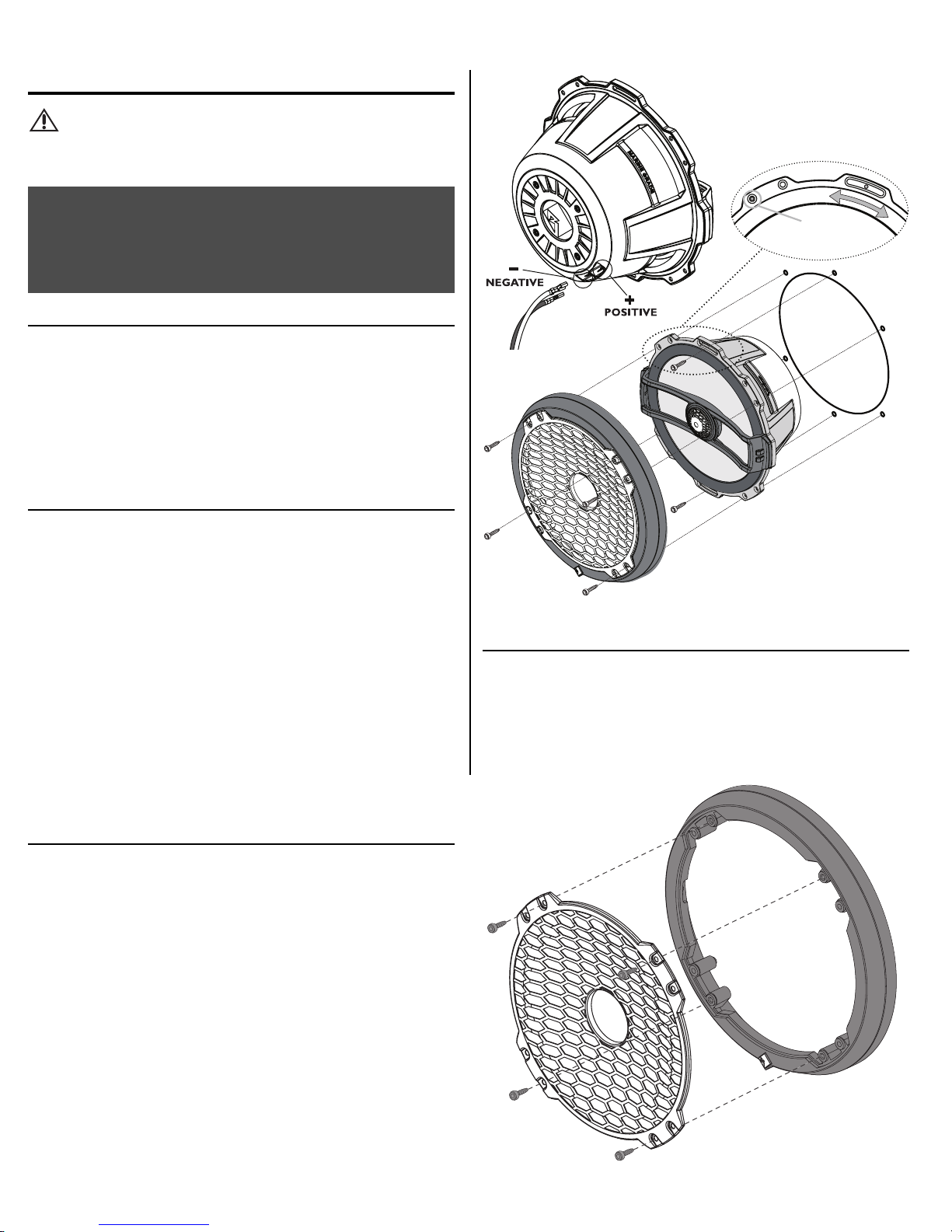
4. Feed the speaker wires through the cutout and connect to the speaker terminals.
Be sure to observe proper polarity when connecting the wires.The speaker's
positive terminal is indicated with a "+".
5. Fit the speaker into the cutout and install the screws in the slots at the top
and bottom.This will allow you to rotate the speaker to match the remaining
mounting holes.When aligned, tighten the screws.
6. Fit the trim ring over the speaker and mount into place using four (4) screws.
7. Tighten the screws until the speaker and trim ring are snug in place to prevent
rattling. Do not over tighten the screws.
NOTE:
This should be done prior to mounting the trim ring over the speaker,since
the mounting screws will also hold the grille onto the trim ring.
1. Remove the four (4) screws holding the grille to the trim ring and pull away.
2. Reinstall the screws into the trim ring or keep in a safe place in case you wish to
reattach the grille.
S
AFETY
CARTON CONTENTS
CAUTION: Before installation, disconnect the battery
negative (-) terminal to prevent damage
to the unit, fire and/or possible injury.
PRACTICE SAFE SOUND™
Continuous exposure to sound pressure levels over 100dB may
cause permanent hearing loss. High powered auto sound systems
may produce sound pressure levels well over 130dB. Use common
sense and practice safe sound.
• (1) Set Marine Grade M2 Series Full Range Speakers
• (1) Set of decorative trim rings
• (14) Socket head stainless screws
• (1) Socket head driver bit
I
NSTALLATIONCONSIDERATIONS
M
OUNTING
G
RILLEREMOVAL
Cutout
Hole
Position to
Align Holes
Page 3

Specifications subject to change without notice
Specifications subject to change without notice
MARINE GRADE M2 6.5" 8"
M262 M282
A - Trim Ring Diameter-inch 7.03 9.06
(cm) (17.85) (23.00)
B - Trim Ring Height-inch 0.96 1.12
(cm) (2.43) (2.85)
C - Mounting Diameter-inch 5.15 7.09
(cm) (13.08) (18.00)
D - Mounting Depth-inch 2.80 3.42
(cm) (7.12) (8.69)
E - Overall Diameter-inch 6.30 8.19
(cm) (16.00) (20.80)
F - Screw Hole Diameter-inch 5.79 7.76
(cm) (14.70) (19.70)
G - Speaker Displacement - cu.ft. 0.025 0.053
(Liter) (0.70) (1.50)
M - Mass (Weight) - lbs. 2.86 5.39
(kg) (1.30) (2.45)
MARINE GRADE M2 6.5" 8"
M262 M282
Nominal Impedance (ohms) 4 4
Frequency Response (Hz) 53-22kHz 48-22kHz
Voice Coil Diameter - inch 1.0 (2-Layer) 1.25 (2-Layer)
(cm) (2.54) (3.23)
Displacement - cu. ft. 0.025 0.053
(Liter) (0.70) (1.50)
Fs - Free Air Resonance (Hz) 60 50
Qts 0.64 0.53
Vas - cu.ft. 0.445 1.06
(Liter) (12.6) (30.0)
Xmax - inch 0.200 0.280
(cm) (0.5) (0.7)
SPL (dB @ 1w/1m) 88 90
Power Handling-Watts (RMS) 75 100
(Peak) 150 200
PHYSICAL DIMENSIONS SPECIFICATIONS
A
C
D
B
E
F
G
Page 4

F
EATURES
• True Marine Grade Compliance.
• 100% UV stable Centrex®injection molded plastic parts.
• Corrosion resistant gold plated polarized input terminals.
• Injection molded mineral filled polypropylene cone body with UV inhibitors.
• UV & Salt-Fog resistant TPE (Thermo-Plastic Elastomer) surround.
• 1" (25mm) bridge mounted component grade coated aluminum alloy tweeter.
• 18 AWG Corrosion resistant removable Stainless Steel grille cover insert.
• Ultra-flexible fully insulated silicone lead wire.
• Spare terminal set for optional additional tweeters.
• Moisture, tear and fatigue resistant aramid fiber spider.
• Linear, high excursion matched motor magnetics and suspension design.
• Integrated 12 dB per octave sealed crossover with integrated protection circuit.
• Removable trim ring. Available in Black or White color options.
Page 5

S
PEAKERMOUNTINGTEMPLATE
 Loading...