

Page 1
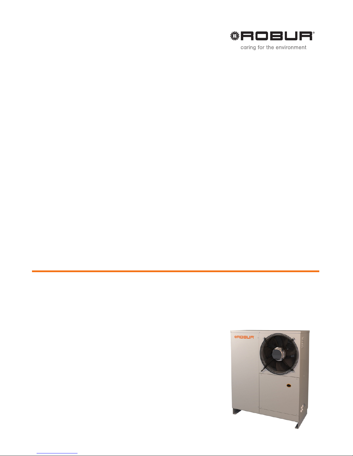
Installation, Use and
Maintenance Manual
K18
Nominal thermal capacity 18,9 kW
Modulating, condensing gas absorption heat pump, using aerothermal
renewable energy and natural gas
Page 2

Revision: A - 3.1
Code: D-LBR687
This Manual has been drawn up and printed by Robur Robur S.p.A.; whole or partial reproduction of this Manual is
forbidden.
The original is led at Robur S.p.A.
Any use of this Manual other than for personal referencing must be previously authorised by Robur S.p.A.
The rights of those who have legitimately led the registered trademarks contained within this publication are not
aected.
With the aim of improving the quality of its products, Robur S.p.A. reserves the right to modify the data and
contents of this Manual without prior notice.
Page 3

Installation, Use and Maintenance Manual – K18
3
INDEX OF CONTENTS
I INTRODUCTION ...............................................4
II SYMBOLS AND DEFINITIONS .........................4
II.1 Key to symbols ...................................................................... 4
II.2 Terms and denitions .........................................................4
III WARNINGS .......................................................4
III.1 General and safety warnings ........................................... 4
III.2 Conformity .............................................................................6
III.3 Exclusions of liability and warranty ............................... 6
1 FEATURES AND TECHNICAL DATA ................7
1.1 Features ...................................................................................7
1.2 Dimensions ............................................................................8
1.3 Components ..........................................................................9
1.4 Electrical wiring diagram ............................................... 12
1.5 Electronic boards .............................................................. 13
1.6 Operation mode ................................................................ 14
1.7 Controls ................................................................................ 14
1.8 Technical characteristics ................................................. 15
2 TRANSPORT AND POSITIONING .................16
2.1 Warnings .............................................................................. 16
2.2 Handling ............................................................................... 16
2.3 Appliance positioning ..................................................... 17
2.4 Minimum clearance distances...................................... 17
2.5 Mounting base ................................................................... 17
3 HEATING ENGINEER ......................................18
3.1 Warnings .............................................................................. 18
3.2 Installation ........................................................................... 18
3.3 Hydraulic connections .................................................... 18
3.4 Water circulation pump .................................................. 19
3.5 Anti-icing function............................................................ 19
3.6 Anti-icing liquid ................................................................. 19
3.7 System water quality ....................................................... 20
3.8 Installation lling .............................................................. 20
3.9 Fuel gas supply .................................................................. 20
3.10 Combustion products exhaust .................................... 21
3.11 Flue gas condensate discharge .................................... 21
3.12 Defrosting water drainage ............................................. 22
4 ELECTRICAL INSTALLER ...............................22
4.1 Warnings .............................................................................. 22
4.2 Electrical systems .............................................................. 22
4.3 Electrical power supply ................................................... 22
4.4 Set-up and control ............................................................ 23
4.5 Water circulation pump .................................................. 25
4.6 How to connect the alarm indicator lamp ............... 25
4.7 How to remote the board error reset.........................26
5 FIRST STARTUP ............................................26
5.1 Preliminary checks ............................................................ 26
5.2 Check combustion parameters .................................... 27
6 NORMAL OPERATION ...................................28
6.1 Warnings .............................................................................. 28
6.2 Switch on and o .............................................................. 28
6.3 Messages on the display ................................................ 28
6.4 On-board electronic controls – Menus and
parameters of the GHP10 board .................................. 28
6.5 Modifying settings ............................................................ 29
6.6 Restarting a locked-out unit - Reset ........................... 32
6.7 Eciency .............................................................................. 32
7 MAINTENANCE ..............................................32
7.1 Warnings .............................................................................. 32
7.2 Pre-emptive maintenance ............................................. 33
7.3 Scheduled routine maintenance ................................. 33
7.4 Periods of inactivity .......................................................... 33
8 DIAGNOSTICS ................................................34
8.1 Operative codes................................................................. 34
APPENDICES ........................................................36
1 Declaration of Conformity ............................................. 36
Page 4
I Introduction
4
I INTRODUCTION
Manual
This Manual is an integral part of the K18 unit and must
be handed to the end user together with the appliance.
Recipients
This Manual is intended for:
▶
end user, for appropriate and safe use of the appliance;
▶
qualied installer, for correct appliance installation;
▶
planner, for specic information on the appliance.
Control device
In order to work, the unit K18requires a control device to be connected by the installer (see Paragraph 1.7p.14).
II SYMBOLS AND DEFINITIONS
II.1 KEY TO SYMBOLS
DANGER
WARNING
NOTE
PROCEDURE
REFERENCE (to other document)
II.2 TERMS AND DEFINITIONS
Appliance/Unit = equivalent terms, both used to designate the
gas powered absorption heat pump.
TAC = Technical Assistance Centre authorised by Robur.
External request =generic control device (e.g. thermostat, tim-
er or any other system) equipped with a voltage-free NO contact
and used as control to start/stop the unit.
OCDS005 Room timer thermostat = control device to control
an appliance K18.
OQLT017 System controller = control system to control an appliance K18 and possibly an additional boiler. It is also able to
control room comfort and DHW production.
Heat generator = equipment (e.g. boiler, heat pump, etc..) producing heating and/or DHW.
GUE (Gas Utilization Eciency) = eciency index of gas heat
pumps, equal to the ratio between the thermal energy produced and the energy of the fuel used (relative to LCV, lower
caloric value).
First start-up = appliance commissioning operation which may
only and exclusively be carried out by a TAC.
GHP10 Board = electronic board on the unit, to control all functions and to provide interface with other devices and with the
user.
III WARNINGS
III.1 GENERAL AND SAFETY WARNINGS
Installer's qualications
Installation must exclusively be performed by a Qualied Firm and by Skilled Personnel, with specic knowledge on heating, cooling, electrical systems and gas
appliances, in compliance with the laws in force in the
Country of installation.
Declaration of Conformity
Upon completing installation, the installing rm shall
issue to the owner/client the appliance's Workmanlike
Conformity Declaration, according to national/local regulations in force and the manufacturer's instructions/
provisions.
Misuse
The appliance must only be used for the purposes for
which it has been designed. Any other use is deemed
hazardous. Incorrect use may aect operation, duration
and safety of the appliance. Adhere to the manufacturer's instructions.
Hazardous situations
▶
Do not start the appliance in hazardous conditions,
such as: gas smell, problems with the plumbing/electrical/gas system, parts of the appliance under water
or damaged, malfunctioning, disabling or bypassing
control and safety devices.
▶
In case of danger, request intervention by skilled
personnel.
▶
In case of danger, switch o the electrical power and
gas supplies only if this can be done in total safety.
▶
Do not entrust children, persons with physical, sensory or mental disabilities or persons with poor knowledge and experience with use of the appliance.
Gas component tightness
Page 5
III Warnings
Installation, Use and Maintenance Manual – K18
5
▶
Before performing any operation on gas ducting
components, close the gas cock.
▶
Upon completing any procedure, perform the tightness test according to regulations in force.
Gas smell
If you smell gas:
▶
Do not use electrical devices such as telephones,
multimeters or other equipment that may cause
sparks next to the appliance.
▶
Shut o the gas supply by turning the cock o.
▶
Disconnect electrical power supply by means of the
external isolation switch in the power supply electrical panel.
▶
Use a telephone away from the appliance to ask for
intervention from skilled personnel.
Poisoning
▶
Ensure the ue gas ducts are tightness and compliant with the regulations in force.
▶
Upon completing any procedure, ensure components are tightness.
Moving parts
The appliance contains moving parts.
▶
Do not remove guards during operation, and in any
case prior to disconnecting the power supply.
Burn hazard
The appliance contains very hot parts.
▶
Do not open the appliance and do not touch internal
components before the appliance has cooled down.
▶
Do not touch the ue gas exhaust before it has
cooled down.
Pressure vessels
The appliance has a sealed circuit classied as pressure vessel, the tightness of which is tested by the
manufacturer.
▶
Do not carry out any intervention on the sealed circuit or on the appliance's valves.
Water-ammonia solution
The K18 unit uses the ammonia-water absorption cycle.
The water-ammonia solution is contained in the tightness circuit. The solution is harmful for health if it is ingested, inhaled or comes in contact with the skin.
▶
In the event of coolant leak keep away and disconnect the power and gas supply (only if it is possible
to do so with no danger).
▶
Request assistance from the TAC.
Electrocution hazard
▶
Disconnect the electrical power supply before any
work/procedure on appliance components.
▶
For electrical connections exclusively use compliant
components and according to the specications provided by the manufacturer.
▶
Ensure the appliance cannot be accidentally
switched back on.
Earthing
Electrical safety depends on eective earthing system,
correctly connected to the appliance and installed according to the regulations in force.
Distance from combustible or ammable materials
▶
Do not store ammable materials (paper, solvents,
paint, etc.) in the vicinity of the appliance.
Limescale and corrosion
Depending on the chemical/physical properties of the
system water, limescale or corrosion may damage the
appliance (Paragraph 3.7p.20).
▶
Check system tightness.
▶
Avoid frequent top-ups.
Chloride concentration
The concentration of chlorides or free chlorine in the
system water must not exceed the values in Table
3.2p.20.
Aggressive substances in air
Halogenated hydrocarbons containing chlorine and
uorine compounds cause corrosion. The supply/ventilation air of the appliance must be free from aggressive
substances.
Acid ue gas condensate
▶
Discharge the acid condensate of combustion ue
gas, as indicated in Paragraph 3.11p. 21, in compliance with current exhaust regulations.
Switching the appliance o
Disconnecting the power supply while the appliance
is running may cause permanent damage to internal
components.
▶
Except in the event of danger, do not disconnect
the power supply to switch o the appliance, but always and exclusively act through the control device
provided.
In the event of failure
Operations on internal components and repairs may
exclusively be carried out by a TAC, only using original
parts.
▶
In the event of failure of the appliance and/or breakage of any component, do not attempt to repair and/
or restore and immediately contact the TAC.
Routine maintenance
Page 6
III Warnings
6
Proper maintenance assures the eciency and good
operation of the appliance over time.
▶
Maintenance must be performed according to the
manufacturer's instructions (see Chapter 7 p. 32)
and in compliance with current regulations.
▶
Appliance maintenance and repairs may only be entrusted to rms legally authorised to work on gas appliances and systems.
▶
Enter into a maintenance contract with an authorised specialised rm for routine maintenance and for
servicing in case of need.
▶
Only use original parts.
Decommissioning and disposal
If the appliance is to be disposed of, contact the manufacturer for its disposal.
Keep the Manual
This "Installation, Use and Maintenance Manual" must
always accompany the appliance and must be handed
to the new owner or installer in the event of sale or
removal.
III.2 CONFORMITY
EU Directives and standards
The absorption heat pumps of the GAHP series are certied as
conforming to standard EN 12309 and comply with the essential
requirements of the following Directives:
▶
2009/142/EC "Gas Appliances Directive" as amended and
added.
▶
2004/108/EC "Electromagnetic Compatibility Directive" as
amended and added.
▶
2006/95/EC "Low Voltage Directive" as amended and added.
▶
2006/42/EC "Machine Directive" as amended and added.
▶
97/23/EEC "Pressure Equipment Directive" as amended and
added.
Furthermore, they comply with the requirements of the following standards:
▶
UNI EN 677 Specic requirements for condensing boilers
with nominal heating capacity up to 70 kW.
▶
EN 378 Refrigerating systems and heat pumps.
Other applicable provisions and standards
The design, installation, operation and maintenance of the systems shall be carried out in compliance with current applicable
regulations, depending on the Country and location, and in
accordance with the manufacturer's instructions. In particular,
regulations regarding the following shall be complied with:
▶
Gas systems and equipment.
▶
Electrical systems and equipment.
▶
Heating and air conditioning systems, and heat pumps.
▶
Environmental protection and combustion products exhaust.
▶
Fire safety and prevention.
▶
Any other applicable law, standard and regulation.
III.3 EXCLUSIONS OF LIABILITY AND
WARRANTY
Any contractual or extra-contractual liability of the
manufacturer for any damage caused by incorrect installation and/or improper use and/or failure to comply
with regulations and with the manufacturer's directions/instructions shall be disclaimed.
In particular, the warranty on the appliance may be rendered void by the following conditions:
▶
Incorrect installation.
▶
Misuse.
▶
Failure to comply with the manufacturer's indications on installation, use and maintenance.
▶
Alteration or modication of the product or any part
thereof.
▶
Extreme operational conditions or however outside of the operational ranges set forth by the
manufacturer.
▶
Damages caused by external agents such as salts,
chlorine, sulphur or other chemical substances contained in the installation water or present in the air of
the installation site.
▶
Abnormal actions transmitted by the plant or installation to the appliance (mechanical stresses, pressure, vibrations, thermal dilations, power surges...).
▶
Accidental damages or due to force majeure.
Page 7

III Warnings
Installation, Use and Maintenance Manual – K18
7
1 FEATURES AND TECHNICAL DATA
1.1 FEATURES
Operation
Based on the thermodynamic water-ammonia absorption cycle
(H20–NH3), the appliance produces hot water using outdoor air
as a renewable energy source (cold source) and natural gas as
primary energy.
The thermodynamic cycle takes place within a hermetically
sealed circuit, in welded construction, perfectly tightness, factory-tested, which does not require any maintenance or refrigerant top-ups.
Mechanical and thermo-hydraulic components
▶
steel sealed circuit, externally treated with epoxy paint;
▶
sealed combustion chamber (type C) suitable for outdoor
installations;
▶
burner equipped with ignition and ame detection device,
controlled by an electronic controller;
▶
titanium stainless steel shell-and-tube water exchanger;
▶
stainless steel, ue gas latent heat recovery exchanger;
▶
air exchanger with nned coil, with steel pipe and aluminium ns;
▶
automatic microprocessor-controlled nned coil automatic
defrosting valve;
▶
standard supplied circulation pump in version C1 (standard).
Control and safety devices
▶
GHP10 electronic board with microprocessor, display and
selection keys;
▶
installation water owmeter;
▶
generator limit thermostat, with manual reset;
▶
ue gas temperature thermostat, with manual reset;
▶
sealed circuit safety relief valve;
▶
by-pass valve, between high and low pressure circuits;
▶
ionisation ame controller;
▶
gas solenoid valve with double shutter;
▶
anti-icing function for water circuit;
▶
condensate discharge obstruction sensor.
Page 8
III Warnings
8
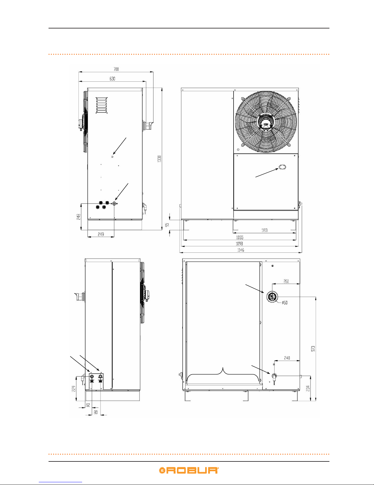
1.2 DIMENSIONS
Figure 1.1 – Dimensions and service plate
B
A
C
H
G
L
E
F
LEGEND
A Water outlet connection Ø ¾’’ M
B Water inlet connection Ø ¾’’ M
C Gas connection Ø 3/8’’ M
D Electrical connection input
E Flue gas outlet Ø 60
F Flue gas condensate drain
G Defrosting water drain
H Green warning light
L Sight glass
Page 9
III Warnings
Installation, Use and Maintenance Manual – K18
9
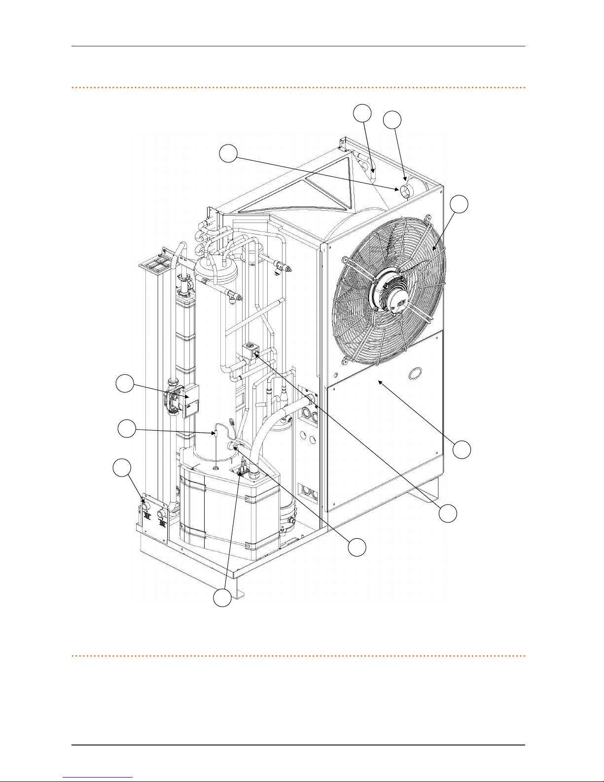
1.3 COMPONENTS
Figure 1.2 – LH front view internal components
LEGEND
1 Fan
2 Ignitor and ame detector
3 PT 1000 Flue gas Temperature Probe
4 Limit thermostat
5 Defrosting valve
6 TA Probe
7 Teva Probe
8 Combustion air inlet
9 Delivery temperature probe
10 Components box
11 Standard circulation pump in version
C1 (standard)
Page 10
III Warnings
10
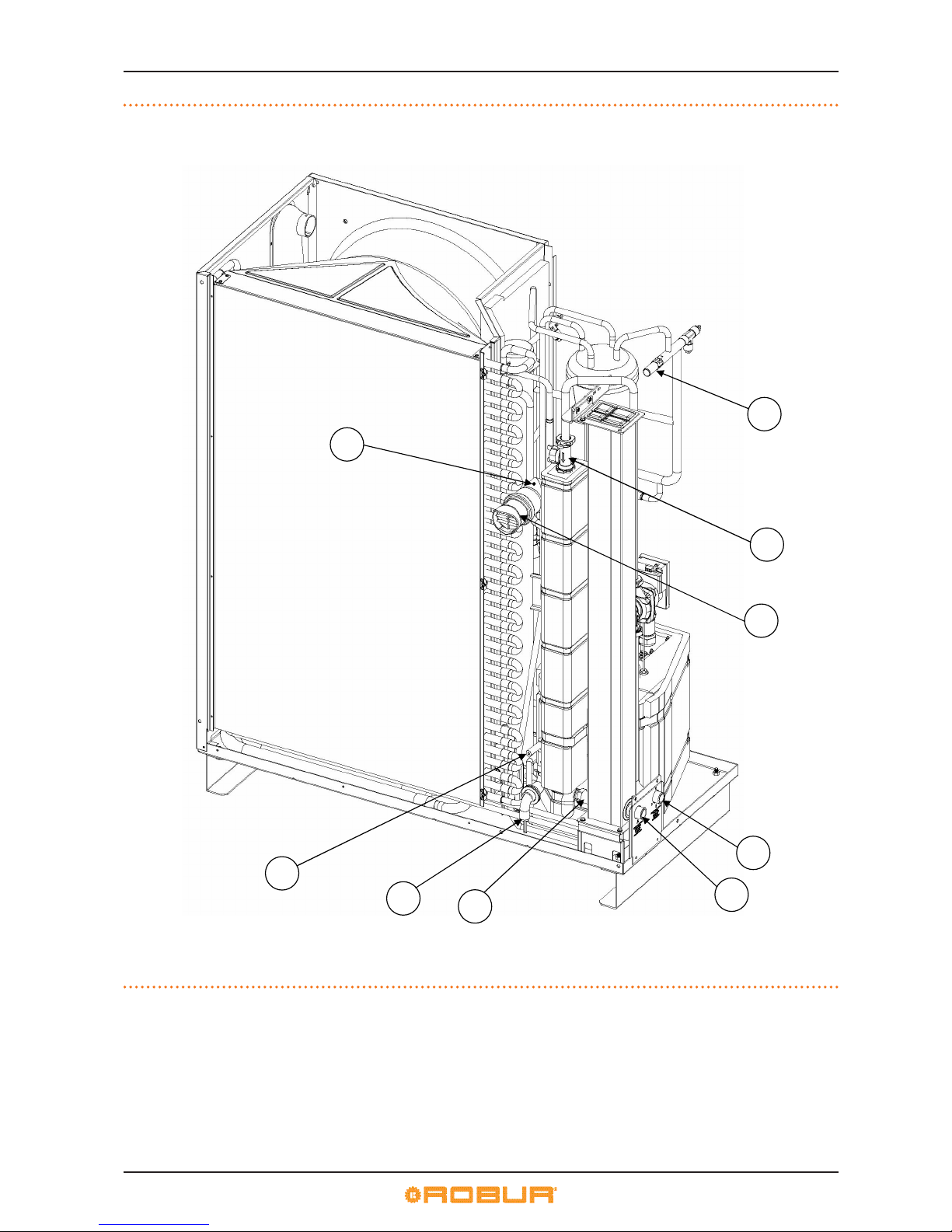
Figure 1.3 – Rear view internal components
LEGEND
1 Safety valve
2 Flow meter
3 Flue gas discharge Ø 60mm
4 Condensate drain
5 Condensate sensor
6 Water delivery connection: "G 3/4" M
7 Water inlet connection: "G 3/4" M
8 Inlet temperature probe
9 120 °C thermal fuse
Page 11
III Warnings
Installation, Use and Maintenance Manual – K18
11
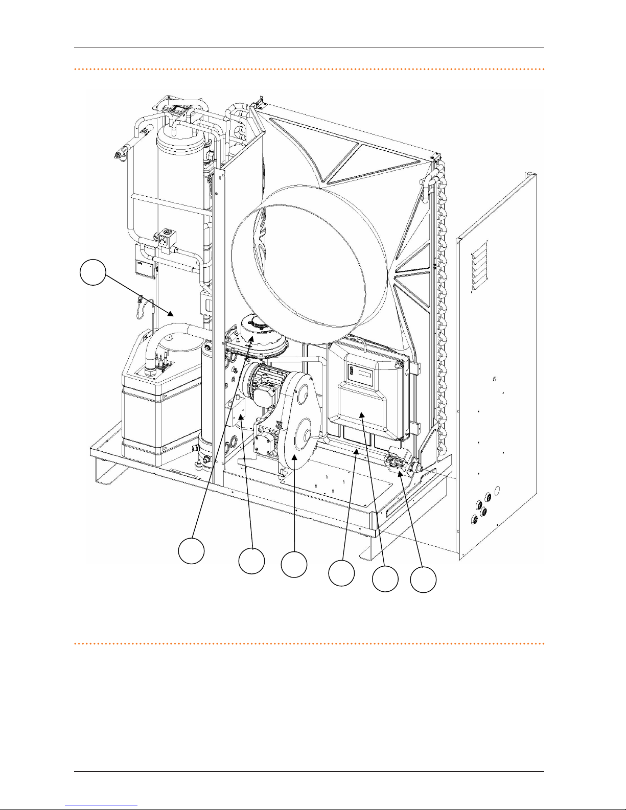
Figure 1.4 – RH front view internal components
LEGEND
1 Gas valve
2 Blower
3 Ignition transformer
4 Oil pump
5 TG Probe
6 Electrical panel
7 Sonda TGV
Page 12
III Warnings
12
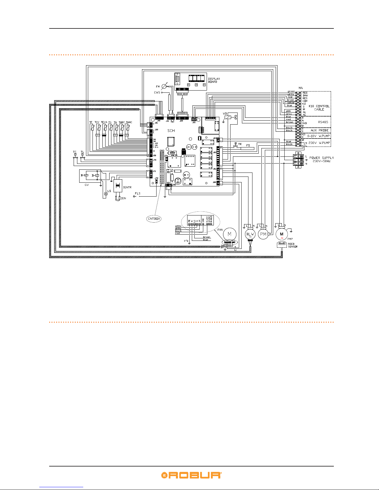
1.4 ELECTRICAL WIRING DIAGRAM
Figure 1.5 – Wiring diagram of the appliance with water pump (C1 version)
LEGEND
SCH GHP10 electronic board
CNTBOX Flame controller
BLW Blower
PM Water pump
PMP Oil pump
IGNTR Ignition transformer
IGN Ignition electrodes
FLS Flame sensor
LS Gas valve ON indicator lamp
GV Gas solenoid valve
TC Manual ue gas thermostat
TL Generator limit thermostat
FM Flowmeter
CWS Condensate water sensor
VD Defrosting valve
FAN Fan
FS Condensate drain heating element
THMC Hot water ow temperature probe
THRC Hot water return temperature probe
TA Ambient air temperature sensor
TG Generator temperature sensor
TEVA Evaporator outlet temperature sensor
TGV Gas valve probe
TF PT1000 ue gas temperature probe
TK Condensate discharge heating element
thermostat
MA Terminal block
REED Oil pump rotation sensor
Page 13
III Warnings
Installation, Use and Maintenance Manual – K18
13
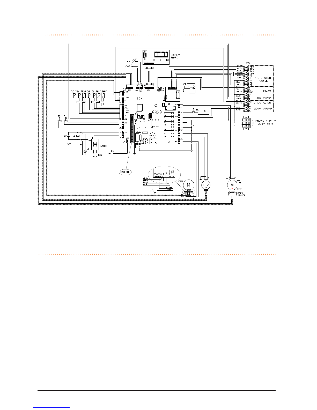
Figure 1.6 – Wiring diagram of the appliance without water pump
LEGEND
SCH GHP10 electronic board
CNTBOX Flame controller
BLW Blower
PMP Oil pump
IGNTR Ignition transformer
IGN Ignition electrodes
FLS Flame sensor
LS Gas valve ON indicator lamp
GV Gas solenoid valve
TC Manual ue gas thermostat
TL Generator limit thermostat
FM Flowmeter
CWS Condensate water sensor
VD Defrosting valve
FAN Fan
FS Condensate drain heating element
THMC Hot water ow temperature probe
THRC Hot water return temperature probe
TA Ambient air temperature sensor
TG Generator temperature sensor
TEVA Evaporator outlet temperature sensor
TGV Gas valve probe
TF PT1000 ue gas temperature probe
TK Condensate discharge heating element
thermostat
MA Terminal block
REED Oil pump rotation sensor
1.5 ELECTRONIC BOARDS
The appliance's electrical panel contains:
▶
Electronic Board GHP10 with microprocessor, it controls the
appliance and displays data, messages and operative codes.
The appliance is monitored and programmed by interacting
with the display and selection keys (Figure 1.7p.14).
Page 14
III Warnings
14
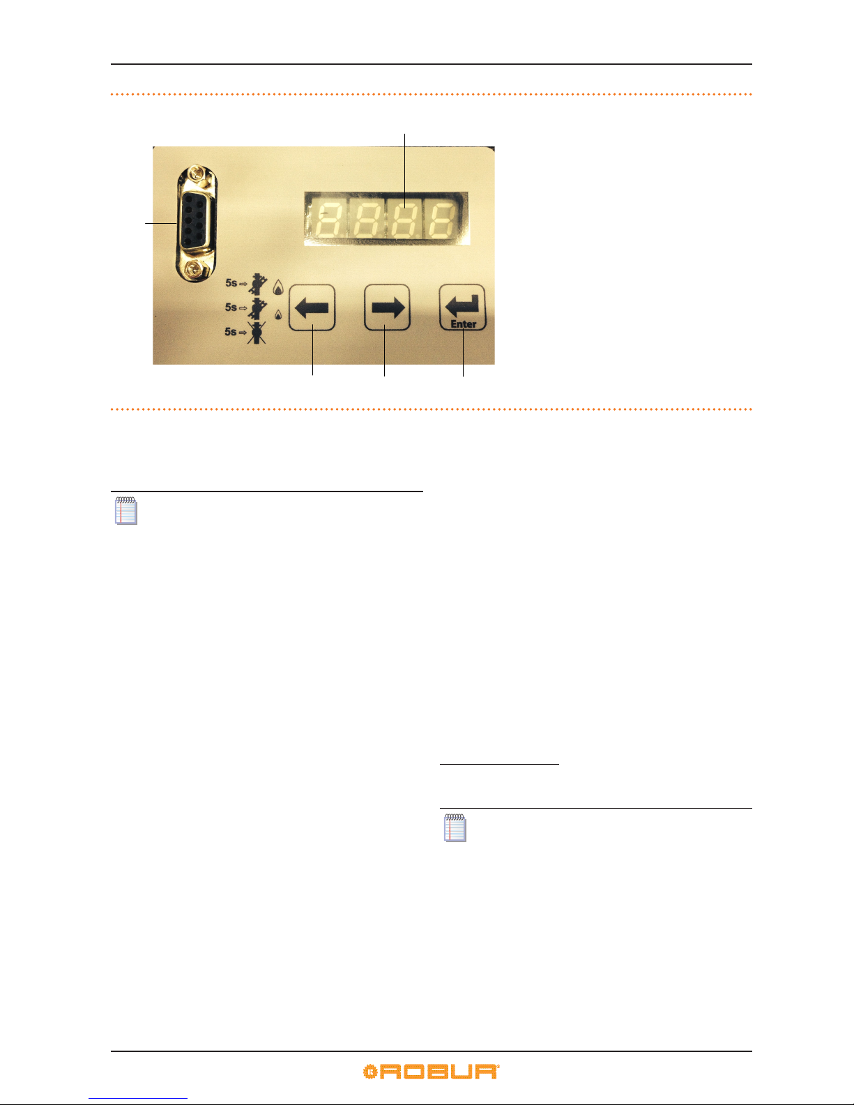
Figure 1.7 – GHP10 board display
1.6 OPERATION MODE
The appliance K18 works in MODULATING mode.
The operating mode depends on parameter 181 of
board GHP10. By default the operating mode is set to
"MODULATING". For any modications contact the installer or the TAC.
1.7 CONTROLS
Control device
The appliance may only work if it is connected to a control device, selected from:
▶
(1) OQLT017 System controller
▶
(2) OCDS005 Room timer thermostat
▶
(3) external request
1.7.1 Control system (1) with OQLT017
The OQLT017 controller is able to control one unit K18 plus a
possible additional boiler. It is also able to control room comfort
and DHW production.
OQLT017 System controller
The main functions are:
▶
control of one unit K18 with variable water set point according to heating curves and type of DHW function;
▶
control of a possible additional boiler;
▶
room comfort control by controlling two heating circuits, of
which one optionally of mixed type, or zone valve control;
control based on heating curves (one for each circuit) and
optionally inuence by the installed room unit/s;
▶
buer tank DHW production control (in dedicated preparation tank);
▶
parameter gures display and setting;
▶
hourly programming on a weekly basis on three temperature levels (comfort, reduced, anti-icing protection);
▶
absence periods programming;
▶
diagnostics;
▶
reset errors.
For additional details and diagrams see Manual OQLT017.
1.7.2 Control system (2) with OCDS005
The OCDS005 timer thermostat is able to control a single unit
K18. In this case the water setpoint is xed or calculated based
on one heating curve only directly controlled by the unit K18; it
is not modiable by the OCDS005 device.
OCDS005 Room timer thermostat
The main functions are:
▶
room timer thermostat for hourly programming on a weekly
basis on various levels of room temperature;
▶
interfacing with the unit K18 through voltage-free request
contact.
For more information refer to Manual OCDS005.
1.7.3 Control system (3) with external request
The appliance may also be controlled via generic enable devices (e.g. thermostats, timer, buttons, contactors...) tted with
voltage-free NO contact. This system only provides elementary
control (on/o, with xed set-point temperature). It is advisable
to possibly limit its use to simple applications only.
For connection of the selected device to the appliance's
electronic board please refer to Paragraph 4.4p.23.
LEGEND
A Display
B Selection keys
C Enter / Access menu
D RS232
Page 15
III Warnings
Installation, Use and Maintenance Manual – K18
15
1.8 TECHNICAL CHARACTERISTICS
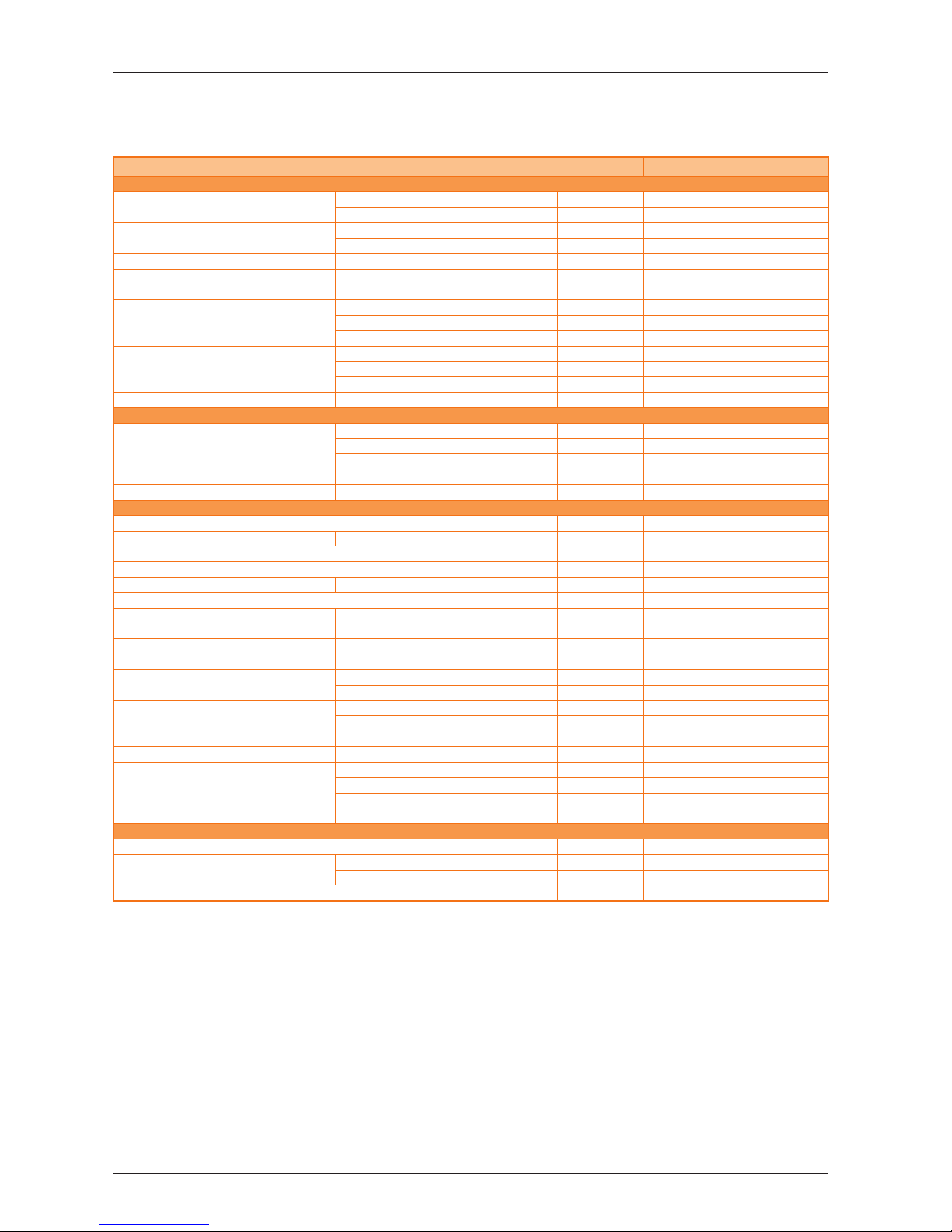
Table 1.1 – K18 Technical data
K18
HEATING MODE
OPERATING POINT A7W50
G.U.E. gas usage eciency % 157 (1)
Thermal power kW 17,6 (1)
OPERATING POINT A7W35
G.U.E. gas usage eciency % 169 (1)
Thermal power kW 18,9 (1)
Heating capacity MAXIMUM kW 11,2
Hot water delivery temperature
maximum for heating °C 65
maximum for DHW °C 70
Hot water inlet temperature
maximum heating °C 55
maximum for DHW °C 60
minimum temperature in continuous operation °C 20 (5)
Hot water ow rate
nominal l/h 1000
maximum l/h 2000
minimum l/h 400
Hot water pressure loss at nominal water ow (A7W35) bar 0,14
ELECTRICAL SPECIFICATIONS
Power supply
Voltage V 230
TYPE SINGLE PHASE
Frequency 50 Hz supply 50
Electrical power absorption nominal w 280 (4)
Degree of protection IP 25
INSTALLATION DATA
Mains gas pressure (G20) mbar 17 - 25 (6)
gas consumption metano G20 (massimo) m3/h 1,2 (2)
Maximum water pressure in operation bar 4
Maximum ow ue condensate l/h 1,5
Defrosting water ow maximum l/min 0,2
Water content inside the apparatus l 1
Water tting
TYPE M
thread " G 3/4
Gas connection
TYPE M
thread " G 3/8
Fume outlet
Dimensions mm 60
Residual head Pa 40
Dimensions
width mm 1146
depth mm 630 (3)
height mm 1330
Weight In operation kg 230
Pump data (only for C1 versions)
Maximum head m a.c. 7,5
Residual head m a.c. 4,0
Nominal ow at the max.available head l/h 1500
Maximum electrical consumption w 75
GENERAL INFORMATION
INSTALLATION MODE B23P - B53P
REFRIGERANT FLUID
AMMONIA R717 kg 5,2
WATER H2O kg 6,8
MAXIMUM PRESSURE OF THE REFRIGERANT CIRCUIT bar 32
Note:
(1) As per standard EN12309-2
(2) PCI (G20) 34,02 MJ/m3 (1013mbar 15 °C)
(3) Clearance dimensions without ue gas exhaust duct
(4) The data excluded electrical consumption of the standard tted pump (75 W )
(5) Lower temperatures are admitted temporarily
(6) The LPG version is available on request
Page 16
2 Transport and positioning
16
Table 1.2 – PED data
K18
PED data
COMPONENTS UNDER PRESSURE
Generator l 18,2
Cooling volume transformer l 3,0
Absorber/condenser l 2,2
Cooling absorber solution l 1.78
Solution pump l 2,8
TEST PRESSURE (IN AIR) bar g 55
MAXIMUM PRESSURE OF THE REFRIGERANT CIRCUIT bar g 32
FILLING RATIO kg of NH3/l 0,186
FLUID GROUP GROUP 1°
2 TRANSPORT AND POSITIONING
2.1 WARNINGS
Damage from transport or installation
The manufacturer shall not be liable for any damage
during appliance transport and installation.
On-site inspection
▶
Upon arrival at the site, ensure there is no transport
damage on packing, metal panels or nned coil.
▶
After removing the packing materials, ensure the appliance is intact and complete.
Packing
▶
Only remove the packing after placing the appliance
on site.
▶
Do not leave parts of the packing within the reach of
children (plastic, polystyrene, nails...) since they are
potentially dangerous.
Weight
▶
The lifting equipment must be suitable for the load.
▶
Do not stand under suspended loads.
2.2 HANDLING
Handling and lifting
▶
Always handle the appliance in its packing, as delivered by
the factory.
▶
Use slings to lift the appliance.
▶
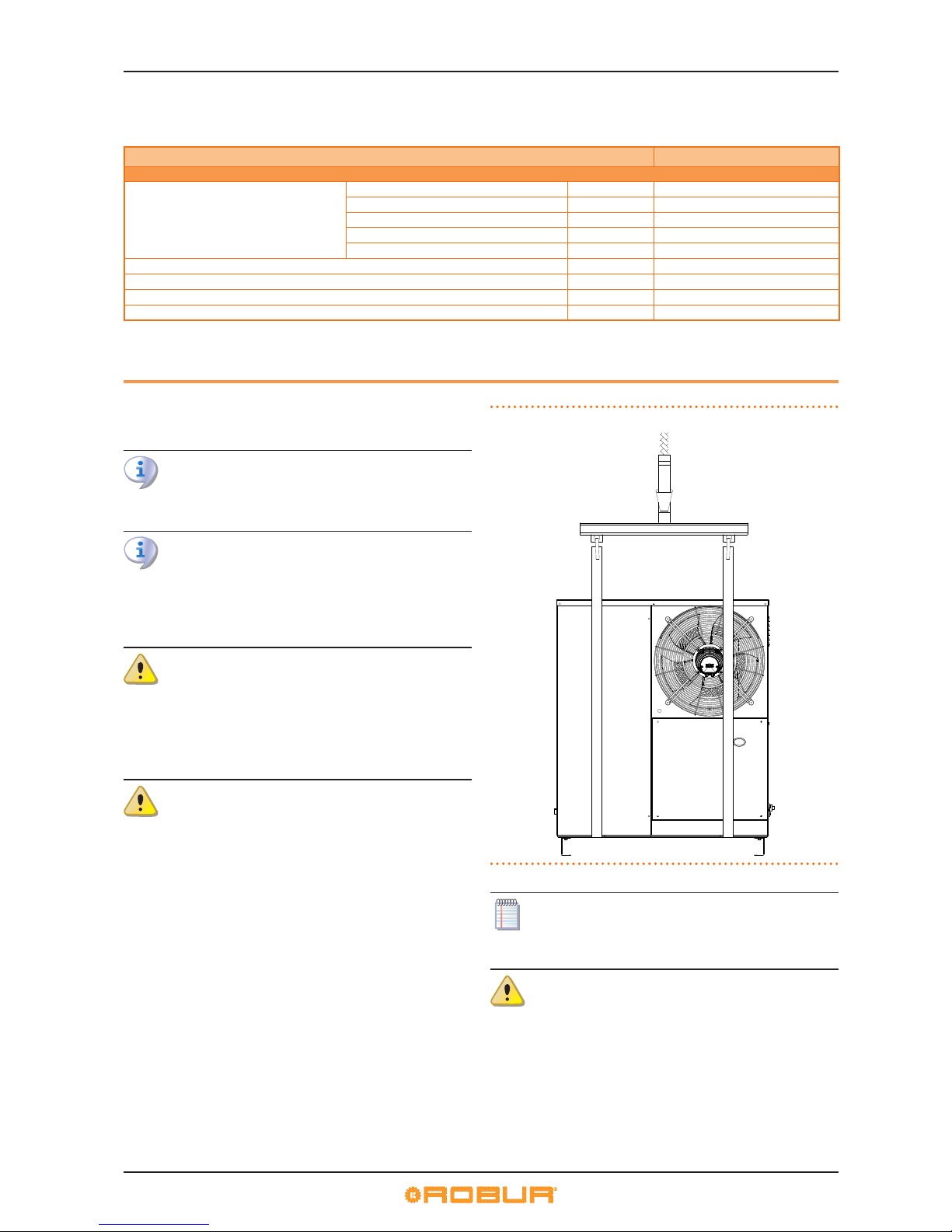
Use lifting beams to avoid damaging the outer panels and
nned coil (Figure 2.1p.16).
▶
Comply with safety regulations at the installation site.
Figure 2.1 – Instruction for lifting
In the event of handling with forklift or pallet truck,
comply with the handling instructions shown on the
packing.
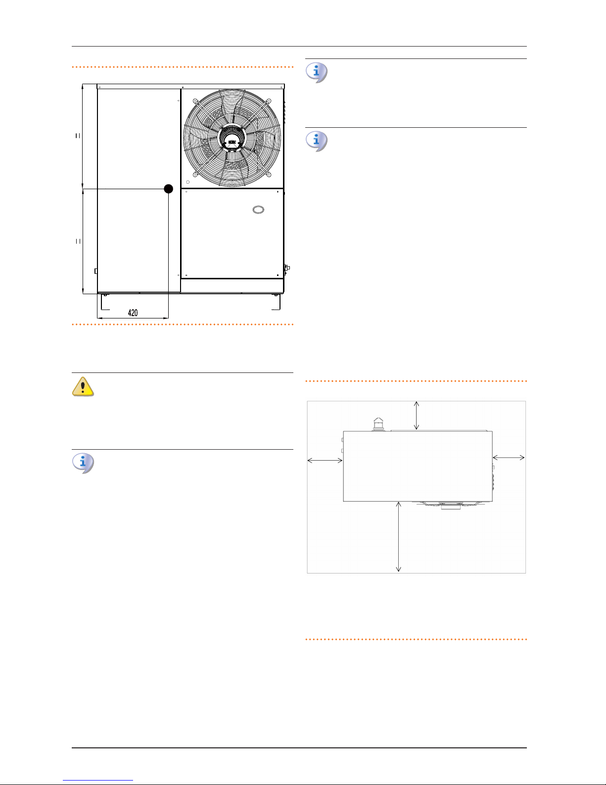
Pay attention to the centre of gravity of the unit which is
o its centre (Figure 2.2p.17).
Page 17
2 Transport and positioning
Installation, Use and Maintenance Manual – K18
17
Figure 2.2 – Unit centre of gravity position
2.3 APPLIANCE POSITIONING
Do not install inside a room
The appliance is type-approved for external installation.
▶
Do not install inside a room, not even if it has
openings.
▶
In no event start the appliance inside a room.
Unit ventilation K18
The aerothermal appliance requires a large space, ventilated and free from obstacles, to enable smooth ow
of air to the nned coil and free air extraction from the
fan outlet, with no air recirculation. Incorrect ventilation
may aect eciency and cause damage to the appliance. The manufacturer shall not be liable for any incorrect choices of the place and setting of installation.
Where to install the appliance
▶
The appliance may be installed at ground level, on a terrace
or on a roof, compatibly with its dimensions and weight.
▶
It must be installed outside buildings, in an area of natural air
circulation, outside the dripping path of drainpipes or similar. It does not require protection from weathering.
▶
No obstruction or structure must hinder the air ow from the
fan, nor ue gas exhaust.
▶
The appliance's ue gas exhaust must not be immediately
close to openings or air intakes of buildings, and must comply with environmental regulations.
▶
Do not install near the exhaust of ues, chimneys or hot
polluted air. In order to work correctly, the appliance needs
clean air.
Install the appliance so the external pipes are as short as
possible, complying with minimum required distances
(Paragraph 2.4p.17).
Defrosting water drainage
In winter, it is normal for frost to form on the nned coil
and for the appliance to perform defrosting cycles.
▶
To prevent overowing and damage provide for a
drainage system.
Acoustic issues
▶
Pre-emptively assess the appliance's sound eect in connection to the site, taking into account that building corners, enclosed courtyards, restricted spaces may amplify the acoustic impact due to the reverberation phenomenon.
2.4 MINIMUM CLEARANCE DISTANCES
Distances from combustible or ammable materials
▶
Keep the appliance away from combustible or ammable
materials or components, in compliance with applicable
regulations.
Clearances around the appliance
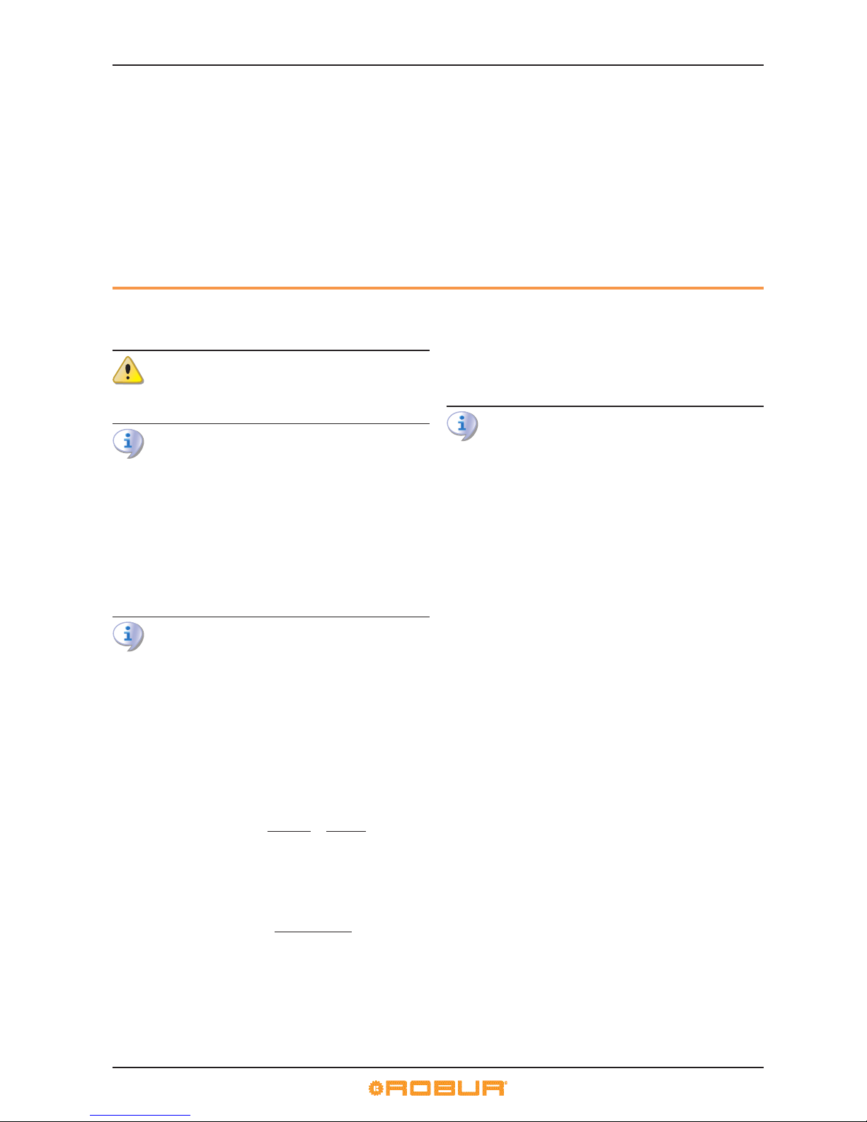
The minimum clearance distances shown in Figure 2.3p. 17
(barring any stricter regulations) are required for safety, operation and maintenance.
Figure 2.3 – Minimum clearance distances
A
B
C
D
LEGEND
A 500 mm
B 300 mm
C 500 mm
D 1500 mm
Unit top view
2.5 MOUNTING BASE
Mounting base constructive features
▶
Place the appliance on a levelled at surface made of reproof material and able to withstand its weight.
Page 18
3 Heating engineer
18
(1) - installation at ground level
▶
Failing a horizontal supporting base, make a at and levelled
concrete base, at least 100-150 mm larger than the appliance dimensions per side.
(2) - installation on terrace or roof
▶
The structure of the building must support the total weight
of the appliance and the supporting base.
▶
If necessary, provide a maintenance walkway around the appliance.
Anti vibration mountings
Although the appliance's vibrations are minimal, resonance
phenomena might occur in roof or terrace installations.
▶
Use vibration damper supports (available as optional features).
▶
Also provide anti-vibration joints between the appliance
and water and gas pipes.
3 HEATING ENGINEER
3.1 WARNINGS
General warnings
Read the warnings in Chapter III p. 4, providing important information on regulations and on safety.
Compliance with installation standards
Installation must comply with applicable regulations in
force, based on the installation Country and site, in matters of safety, design, implementation and maintenance
of:
▶
heating systems;
▶
cooling systems;
▶
gas systems;
▶
ue gas exhaust;
▶
ue gas condensate discharge.
Installation must also comply with the manufacturer's
provisions.
3.2 INSTALLATION
Primary and secondary circuit
▶
In many cases it is advisable to divide the hydraulic system
into two parts, primary and secondary circuit, uncoupled by
a hydraulic separator, or possibly by a tank that also acts as
inertial volume/thermal inertia.
Constant ot variable water ow
The unit K18 may operate with constant or variable water ow.
System and components must be designed and installed
consistently.
Minimum water content
High thermal inertia is conducive to ecient appliance operation. Very short ON/OFF cycles are to be avoided.
▶
If necessary, provide for an inertial volume, to be suitably
sized.
3.3 HYDRAULIC CONNECTIONS
Plumbing ttings
on the left, at the bottom, connection plate (Figure 1.1p.8).
▶
A (= in) 3/4" M - WATER INPUT (r = inlet from the system) ;
▶
B (= out) 3/4" M - WATER OUTPUT (m = outlet to the system).
Hydraulic pipes, materials and features
▶
Use pipes for heating/cooling systems, protected from
weathering, insulated for thermal dispersion.
Pipe washing
▶
Before connecting the appliance,accurately wash
the water and gas piping and any other system component, removing any residue.
Minimum components of primary plumbing circuit
▶
Always provide, near the appliance:
on water piping, both output and input (m/r)
▶
2 ANTIVIBRATION JOINTS on water ttings;
▶
2 PRESSURE GAUGES;
▶
2 ISOLATION BALL VALVES;
on the input water piping (r)
▶
1 SEPARATOR FILTER;
▶
1 FLOW REGULATION VALVE;
▶
1 WATER CIRCULATION PUMP, with ow side towards the
group (ONLY to be provided in versions without in-built
pumps);
on the output water piping (m)
▶
1 SAFETY VALVE (3 bar);
▶
1 EXPANSION TANK of the individual unit
Page 19
3 Heating engineer
Installation, Use and Maintenance Manual – K18
19
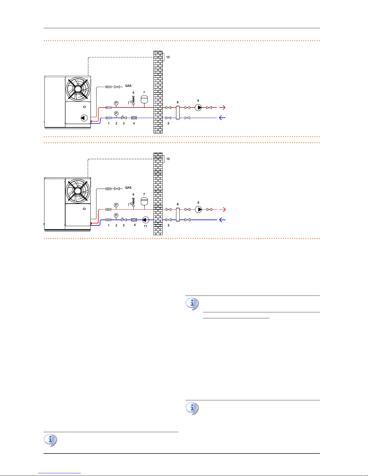
Figure 3.1 – Unit water diagram with built-in pump
Figure 3.2 – Unit water diagram without built-in pump
3.4 WATER CIRCULATION PUMP
The appliances in C1 version (standard) are equipped with a variable ow circulation pump. For the data of the pump, refer to
Table 1.1p.15.
For units without in-built circulation pump, the pump (ow and
head) must be selected and installed based on pressure losses
of water/primary circuit (piping + components + exchange terminals + appliance).
For the appliance's pressure losses refer to Table 1.1p.15.
(1) CONSTANT FLOW circulating pump
The circulating pump must be obligatorily controlled by the appliance's electronic board (GHP10) (see Paragraph4.5.1p.25).
(2) VARIABLE FLOW circulating pump
For variable ow operation, use of a Wilo Stratos Para pump is
obligatory , supplied as accessory on demand, to be connected
to the GHP10 electronic board (see Paragraph 4.5.2p.25).
3.5 ANTIICING FUNCTION
Active anti-icing self-protection
The appliance is equipped with an active antifreeze self-protection system to prevent icing. The anti-icing function (activated
by default) automatically starts the primary circulation pump
and, if required, the burner too, when the outside temperature
approaches zero.
Electrical and gas continuity
The active anti-icing self-protection is only eective
if the power and gas supplies are assured. Otherwise,
anti-icing liquid might be required.
3.6 ANTIICING LIQUID
Precautions with glycol
The manufacturer disclaims any liability for any damage
caused by improper glycol use.
▶
Always check product suitability and its expiry date
with the glycol supplier. Periodically check the product's preservation state.
▶
Do not use car-grade anti-icing liquid (without inhibitors), nor zinc-coated piping and ttings (incompatible with glycol).
▶
Glycol modies the physical properties of water (density, viscosity, specic heat...). Size the piping, circulation pump and thermal generators accordingly.
▶
With automatic system water lling, a periodic check
of the glycol content is required.
With high glycol percentage (> 20…30%)
If the glycol percentage is ≥30% (for ethylene glycol) or
≥20% (for propylene glycol) the TAC must be alerted before rst start-up.
LEGEND
1 Anti-vibration connection
2 Pressure gauge
3 Flow regulation valve
4 Water lter
5 Isolation valves
6 Safety valve (3 bar)
7 Expansion tank
8 Hydraulic separator / 4-pipe buer tank
9 Water pump (secondary circuit)
10 Control device
LEGEND
1 Anti-vibration connection
2 Pressure gauge
3 Flow regulation valve
4 Water lter
5 Isolation valves
6 Safety valve (3 bar)
7 Expansion tank
8 Hydraulic separator / 4-pipe buer tank
9 Water pump (secondary circuit)
10 Control device
11 Water pump (primary circuit)
Page 20
3 Heating engineer
20
Type of anti-icing glycol
Inhibited type glycol is recommended to prevent oxidation
phenomena.
Glycol eects
The Table 3.1 p. 20 shows, indicatively, the eects of using a
glycol depending on its %.
Table 3.1 – Technical data for lling the hydraulic circuit
GLYCOL % 10 15 20 25 30 35 40
WATER-GLYCOL MIXTURE FREEZING TEMPERATURE -3°C -5°C -8°C -12°C -15°C -20°C -25°C
PERCENTAGE OF INCREASE IN PRESSURE DROPS -- 6% 8% 10% 12% 14% 16%
LOSS OF EFFICIENCY OF UNIT -- 0,5% 1% 2% 2,5% 3% 4%
3.7 SYSTEM WATER QUALITY
Responsibility of the user/operator/installer
The installer, operator and user must assure system water quality (Table 3.2p.20). Failure to comply with the
manufacturer's guidelines may aect operation, integrity and life of the appliance, voiding the warranty.
Table 3.2 – Chemical and physical parameters of water
CHEMICAL AND PHYSICAL PARAMETERS OF WATER IN HEATING/COOLING
SYSTEMS
PARAMETER
UNIT OF
MEASUREMENT
ALLOWABLE RANGE
pH \ >7
(1)
Chlorides mg/l < 125
(2)
Total hardness (CaCO
3)
°f < 15
°d < 8.4
Iron mg/kg < 0.5
(3)
Copper mg/kg < 0.1
(3)
Aluminium mg/l < 1
Langelier’s index \ 0-0,4
HARMFUL SUBSTANCES
Free chlorine mg/l < 0.2
(3)
Fluorides mg/l < 1
Sulphides ABSENT
1 with aluminium or light alloys radiators, pH must also be low-
er than 8 (in compliance with applicable rules)
2 value referred to the maximum water temperature of 80 °C
3 in compliance with applicable rules
System water features
Free chlorine or water hardness may damage the appliance.
Adhere to the chemical-physical parameters in Table 3.2p.20
and the regulations on water treatment for residential and industrial heating systems.
Water topping up
The chemical-physical properties of the system's water may alter
over time, resulting in poor operation or excessive topping up.
▶
Ensure there are no leaks in the installation.
▶
Periodically check the chemical-physical parameters of the
water, particularly in case of automatic topping up.
Chemical conditioning and washing
Water treatment/conditioning or system washing carried out carelessly may result in risks for the appliance,
the system, the environment and health.
▶
Contact specialised rms or professionals for water
treatment or system washing.
▶
Check compatibility of treatment or washing products with operating conditions.
▶
Do not use aggressive substances for stainless steel
or copper.
▶
Do not leave washing residues.
3.8 INSTALLATION FILLING
How to ll up the system
After completing all water, electrical and gas
connections:
1. Pressurise (at least 1.5 bar) and vent the hydraulic
circuit.
2. Circulate water.
3. Check and clean the lter on the inlet pipe.
4. Repeat items 1, 2 and 3. until the pressure has stabilised (at least 1.5 bar).
3.9 FUEL GAS SUPPLY
Gas connection
▶
3/8" M
on the right, at the bottom (Figure 1.1p.8).
▶
Install an anti-vibration connection between the appliance
and the gas piping.
Mandatory shut-o valve
▶
Provide a gas shut-o valve (manual) on the gas supply line,
to isolate the appliance when required.
▶
Perform connection in compliance with applicable regulations.
Gas pipes sizing
The gas pipes must not cause excessive load losses and, consequently, insucient gas pressure for the appliance.
Supply gas pressure
The appliance's gas supply pressure, both static and dynamic,
must comply with Table 1.1p.15, with tolerance ± 15%.
Non compliant gas pressure (Table 1.1 p. 15) may
damage the appliance and be hazardous.
Vertical pipes and condensate
▶
Vertical gas pipes must be tted with siphon and discharge
of the condensate that may form inside the pipe.
▶
If necessary, insulate the piping.
Page 21
3 Heating engineer
Installation, Use and Maintenance Manual – K18
21
3.10 COMBUSTION PRODUCTS EXHAUST
Compliance with standards
The appliance is approved for connection to a combustion products exhaust duct for the types shown in Table
1.1p.15.
Flue gas exhaust connection
▶
Ø 60 mm (with gasket),
on the rear, at the top (Figure 1.1p.8).
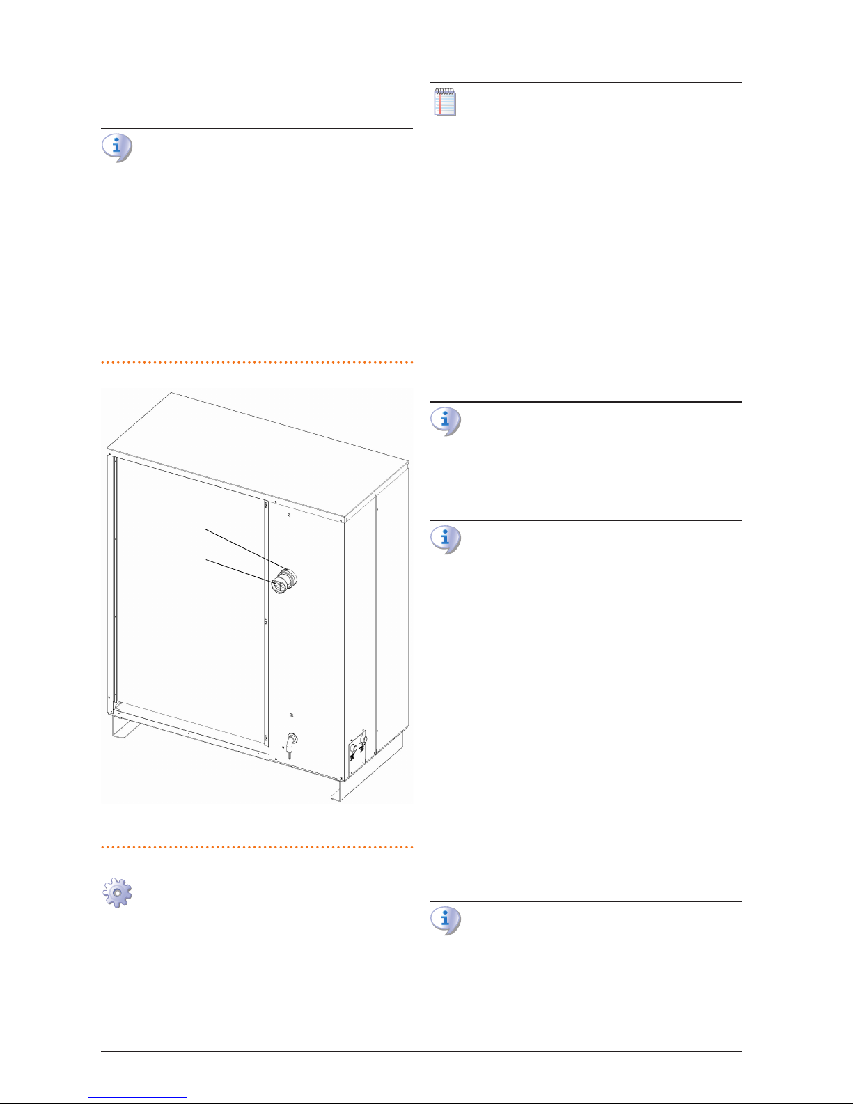
Flue gas exhaust kit
The appliance is supplied with ue gas exhaust kit, to be tted
by the installer, including (Figure 3.3p.21):
▶
1 Rain cover Ø 60 mm;
▶
1 Terminal Ø 60 mm;
Figure 3.3 – Fume outlet
LEGEND
A Rain cover Ø 60 mm
B Terminal Ø 60 mm
How to install the ue gas exhaust kit
Figure 3.3p.21:
1. Remove the adhesive applied to the ue gas exhaust.
2. Fit the rain cover (A) onto the terminal (B).
3. Fit the rain cover and terminal assembly onto the collar on the ue gas exhaust.
The sticker prevents water and foreign bodies entering the appliance before the fumes kit is installed. The
sticker should thus be removed only when the kit itself
has been fully assembled and installed.
Any ue
If necessary, the appliance may be connected to a ue.
▶
Consider residual head for sizing the chimney (Table
1.1 p. 15) and the following data: ue gas temperature =
60°C, ue gas ow = 19 kg/h.
▶
The ue must be designed, sized, tested and constructed by
a skilled form, with materials and components complying
with the regulations in force in the country of installation.
▶
Always provide a socket for ue gas analysis, in an accessible
position.
3.11 FLUE GAS CONDENSATE DISCHARGE
The K18 unit is a condensing appliance and therefore produces
condensate from combustion ue gases.
Condensate acidity and exhaust regulations
The ue gas condensate contains aggressive acid substances. Refer to applicable regulations in force for condensate exhaust and disposal.
▶
If required, install an acidity neutraliser of adequate
capacity.
Do not use gutters to discharge the condensate
Do not discharge the fume condensate in gutters, due
to the risk of materials corrosion and ice formation.
Flue gas condensate connection
The connection for ue gas condensate discharge is located on
the rear of the appliance (reference F in Figure 1.1p.8).
▶
The condensate discharge pipe must be connected to a suitable discharge manifold.
▶
The junction between the pipe and the manifold must remain visible.
Flue gas condensate discharge manifold
To make the condensate drain manifolds:
▶
Size the ducts for maximum condensation capacity (Table
1.1p.15).
▶
Use plastic materials resistant to acidity pH 3-5.
▶
Provide for min. 1% slope, i.e. 1 cm for each m of the length
(otherwise a booster pump is required).
▶
Prevent icing.
▶
Dilute, if possible, with domestic waste water (e.g. bathrooms, washing machines, dish washers...), basic and neutralising.
In the rst few minutes of unit operation, that is in conditions of low condensate production, imperceptible
steam or combustion gas might escape the condensate
exhaust, which are not harmful either for machine operation or for the materials used for condensate exhaust.
Page 22
4 Electrical installer
22
3.12 DEFROSTING WATER DRAINAGE
Defrosting
In winter, frost may form on the nned coil and the appliance performs defrosting cycles.
The defrosting water drain point is located at its base (see reference G in Figure 1.1p.8).
Accessory OSCR019 needs to be used to connect the defrosting
water drain to a drain manifold.
Prevent freezing of defrosting water drain by using a heating
wire (by the installer).
4 ELECTRICAL INSTALLER
4.1 WARNINGS
General warnings
Read the warnings in Chapter III p. 4, providing important information on regulations and on safety.
Compliance with installation standards
Installation must comply with applicable regulations in
force, based on the installation Country and site, in matters of safety, design, implementation and maintenance
of electrical systems.
Installation must also comply with the manufacturer's
provisions.
Live components
▶
After placing the appliance in the nal position, and
prior to making electrical connections, ensure not to
work on live components.
Earthing
▶
The appliance must be connected to an eective
earthing system, installed in compliance with regulations in force.
▶
It is forbidden to use gas pipes as earthing.
Cable segregation
Keep power cables physically separate from signal ones.
It is recommended to lay the cables in separate conduits
at least 5 cm from each other.
Do not use the power supply switch to turn the appliance on/o.
▶
Never use the external isolation switch (GS) to turn
the appliance on and o, since it may be damaged
in the long run (occasional black outs are tolerated).
▶
To turn the appliance on and o, exclusively use the
suitably provided control device.
Control of water circulation pump
The water circulation pump of the water/primary circuit
must mandatorily be controlled by the appliance's electronic board. It is not admissible to start/stop the circulating pump with no request from the appliance.
4.2 ELECTRICAL SYSTEMS
Electrical connections must provide:
▶
(a) power supply (Paragraph 4.3p.22);
▶
(b) control system (Paragraph 1.5p.13).
How to perform connections
All electrical connections must be performed in the connecting terminal block located near the Electrical Panel:
1. Ensure the appliance is not live.
2. Remove the appliance's lower front panel.
3. Run the cables through the suitable holes (see references D of 1.1p.8).
4. Identify the appropriate connection terminals.
5. Perform the connections.
6. Replace the lower front panel.
4.3 ELECTRICAL POWER SUPPLY
Power supply line
Provide (by the installer) a protected single phase line (230 V 1-N
50 Hz) with:
▶
1 three-core cable type FG7(O)R 3Gx1.5
▶
1 4 A magnetothermic breaker
The switches must also provide disconnector capability,
with min contact opening 4 mm.
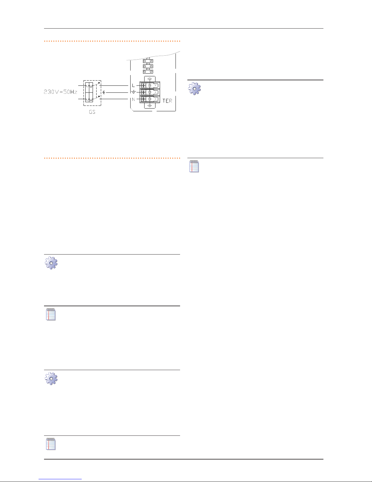
How to connect the power supply
To connect the three-pole power supply cable (Figure
4.1p.23):
1. Access the connection terminal block according to
Procedure 4.2p.22.
2. Connect the three wires to terminal board (TER) as
shown in Figure 4.1p.23.
3. Provide the earth lead-in wire longer than live ones
(last to be torn in the event of accidental pulling).
Page 23
4 Electrical installer
Installation, Use and Maintenance Manual – K18
23
Figure 4.1 – Appliance power supply wiring diagram
LEGEND
TER terminal block
L phase
N neutral
Components NOT SUPPLIED
GS 4A magnetothermic breaker
Connecting the appliance to the power supply mains (230V 1N - 50Hz)
4.4 SETUP AND CONTROL
Control systems, options (1) (2) (3)
Three separate control systems are provided, each with specic
features, components and diagrams:
▶
System (1), with the OQLT017 controller.
▶
System (2), with the OCDS005 timer thermostat.
▶
System (3), with an external request.
OQLT017 Controller (optional)
(System (1) see also Paragraph 1.7p.14)
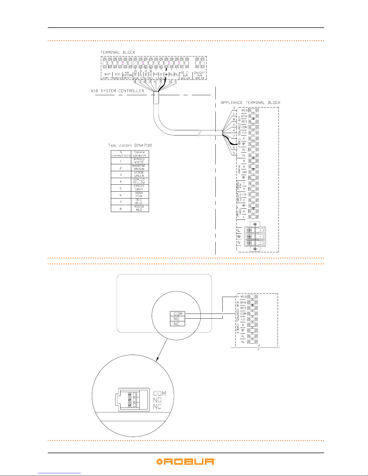
How to connect the OQLT017 Controller
Connection of OQLT017 Controller is eected on the
terminal board located in the Electrical Panel inside the
unit.
For connection use a type LI-YCY 8x0.75 shielded cable
(available as optional).
The cable may not be longer than 30 metres.
1. Access the Electrical Board of the appliance according to the Procedure 4.2p.22.
2. Perform connections as shown in the diagram in Figure 4.2p.24.
OCDS005 Timer thermostat (optional)
(System (2) see also Paragraph 1.7p.14)
How to connect the OCDS005 Timer thermostat
Connection of OCDS005 Timer thermostat is eected
on the terminal board located in the Electrical Panel inside the unit.
1. Access the Electrical Board of the appliance according to the Procedure 4.2p.22.
2. Perform connections as shown in the diagram in Figure 4.3p.24.
The cable may not be longer than 30 metres.
External request
(System (3) see also Paragraph 1.7p.14)
It is required to arrange:
▶
request device (e.g. thermostat, timer, button, ...) tted with
a voltage-free NO contact.
How to connect the external request
Connection of external request is eected on the terminal board located in the Electrical Panel inside the unit.
1. Access the Electrical Board of the appliance according to the Procedure 4.2p.22.
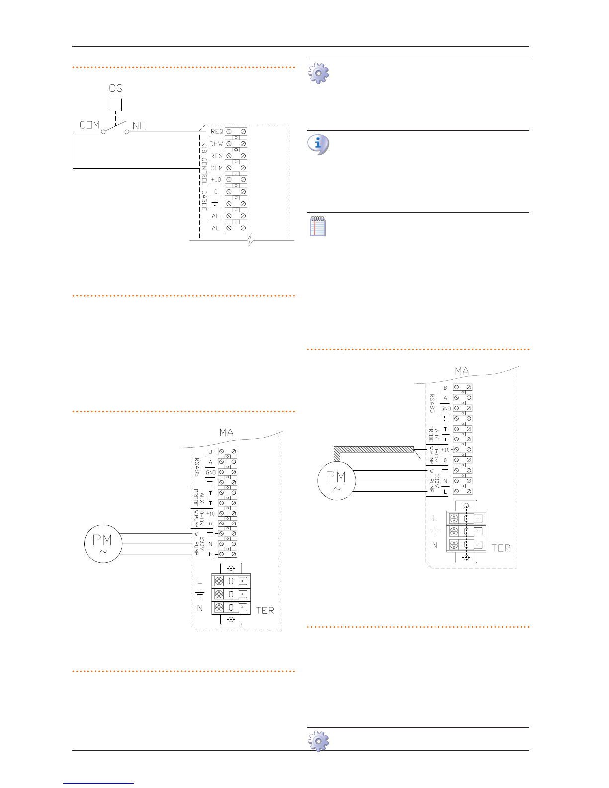
2. Connect the voltage free contact of the external device, through two conductor wires, to terminals COM
and REQ (respectively: common 24 V AC and heating request) of the internal terminal board (Figure
4.4p.25).
The cable may not be longer than 30 metres.
Page 24
4 Electrical installer
24
Figure 4.2 – Connection diagram to OQLT017 system controller
Figure 4.3 – Connection diagram to timer thermostat OCDS005
Page 25
4 Electrical installer
Installation, Use and Maintenance Manual – K18
25
Figure 4.4 – Wiring diagram, external enable connection
LEGEND
COM common
REQ heating request
Components NOT SUPPLIED
CS external request
4.5 WATER CIRCULATION PUMP
The C1 version (standard) is already equipped with a variable
ow circulation pump on-board. For dierent versions, refer to
the following paragraphs.
4.5.1 Option (1) CONSTANT FLOW circulating pump
It must be mandatorily controlled by the GHP10 electronic
board. For connection refer to Figure 4.5p.25.
Figure 4.5 – Constant ow pump connection wiring diagram
LEGEND
MA Connection terminal
block
PM Water pump
N Neutral
L Phase
4.5.2 Option (2) VARIABLE FLOW circulating pump
It must be mandatorily controlled by the GHP10 electronic
board.
How to connect the VARIABLE FLOW circulating
pump
To optimise appliance operation it is required to provide
the primary system with a WILO STRATOS PARA variable
ow pump (available as optional).
The Wilo Stratos Para pump is already standard supplied
with the power supply cable and signal cable, both
1.5m long.
For longer distances, use respectively cable FG7
3Gx1.5mm² and shielded cable 2x0.75 mm² suitable for
0-10V signal.
Neither cable may be longer than 10 metres.
To connect the Wilo Stratos Para pump
(Figure4.6p.25):
1. Connect the pump's brown wire to terminal "0" and
the pump's white wire to terminal "+10" of terminal
board "0-10V CIRC".
2. Isolate the black wire and the blue one.
3. For the pump's power supply connect the brown
wire to terminal “L”; the blue wire to terminal “N” and
the yellow/green wire to the terminal with the earthing symbol of terminal board "CIRC.OUT".
Figure 4.6 – Variable ow pump connection wiring diagram
LEGEND
MA Connection terminal
block
PM Water pump
N Neutral
L Phase
0 Brown wire
+10 White wire
Black wire insulate
Blue wire insulate
4.6 HOW TO CONNECT THE ALARM
INDICATOR LAMP
It is possible to connect a lamp indicating an appliance’s alarm to
the Electrical Panel inside the appliance.
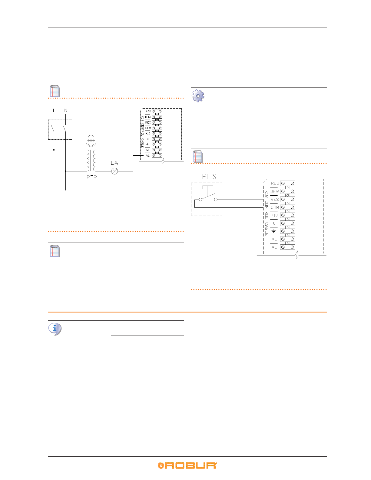
To connect the alarm indicator lamp, follow the instructions
below.
Figure 4.7p.26.
Page 26
5 First start-up
26
1. Access the connection terminal block according to
Procedure 4.2p.22.
2. The cable to connect the lamp must be 2x0,5 mm2.
3. Cut a suitable length of cable.
4. Connect the cable to terminals AL and AL.
The cable may not be longer than 30 metres.
Figure 4.7
LEGEND
L phase
N neutral
Components NOT SUPPLIED
LA general alarm indicator lamp
PTR safety transformer with secondary voltage ≤ 24V (compliant with
norms IEC EN 61558-2-6)
The lamp AL switched on indicates an alarm of the appliance. To know the type of alarm, read through the
sight glass (reference L in Figure 1.1p. 8) the operating code on the display of the electronic board and refer
to Table 8.1p.34.
4.7 HOW TO REMOTE THE BOARD ERROR
RESET
The board error reset may be remoted by connecting a dedicated button to the terminal block in the Electrical Panel inside
the appliance.
Connect the button as instructed below.
Figure 4.8p.26
1. Access the connection terminal block according to
Procedure 4.2p.22.
2. The cable required to connect the reset button must
be 3x0.75mm
2.
3. Cut a suitable length of cable.
4. Connect the cable to terminals COM and RES.
The cable may not be longer than 30 metres.
Figure 4.8
LEGEND
COM common
RES reset errors
Components NOT SUPPLIED
PLS release button
5 FIRST STARTUP
First start-up entails checking/adjusting the combustion parameters and may only be carried out by a TACRobur. NEITHER the user NOR the installation technician
is authorised to perform such operations, under penalty
of voiding the warranty.
5.1 PRELIMINARY CHECKS
Preliminary checks for First start-up
Upon completing installation, before contacting the TAC the installer must check:
▶
water-heating, electrical and gas systems suitable for the required capacities and equipped with all safety and control
devices required by the regulations in force;
▶
absence of leaks in the water and gas systems;
▶
type of gas for which the appliance is designed (methane);
▶
supply gas pressure complying with the values of Table
3.3p., with max tolerance ±15%;
▶
Power supply mains complying with the appliance's rating
plate data;
▶
appliance correctly installed, according to the manufacturer's instructions;
▶
system installed in a workmanlike manner, according to national and local regulations.
Abnormal or hazardous installation situations
Should any abnormal or hazardous installation situations be
found, the TAC shall not perform First start-up and the appliance
shall not be commissioned.
These situations may be:
▶
appliance installed inside a room;
▶
failed compliance with minimum clearances;
▶
insucient distance from combustible or ammable materials;
▶
conditions that do not warrant access and maintenance in
safety;
Page 27
5 First start-up
Installation, Use and Maintenance Manual – K18
27
▶
appliance switched on/o with the main switch, instead of
the control device provided (OQLT017, OCDS005, or external
request);
▶
appliance defects or faults caused during transport or installation;
▶
gas smell;
▶
non-compliant mains gas pressure;
▶
non-compliant ue gas exhaust;
▶
all situations that may involve operation abnormalities or are
potentially hazardous.
Non-compliant system and corrective actions
Should the TAC nd any non conformities, the user/installer is
bound to perform any corrective procedures required by the
TAC .
After performing the remedial actions (the installer's responsibility), if the TAC deems that safety and conformity conditions
are in place, "First start-up" may be eected.
5.2 CHECK COMBUSTION PARAMETERS
Paragraph reserved to TACs.
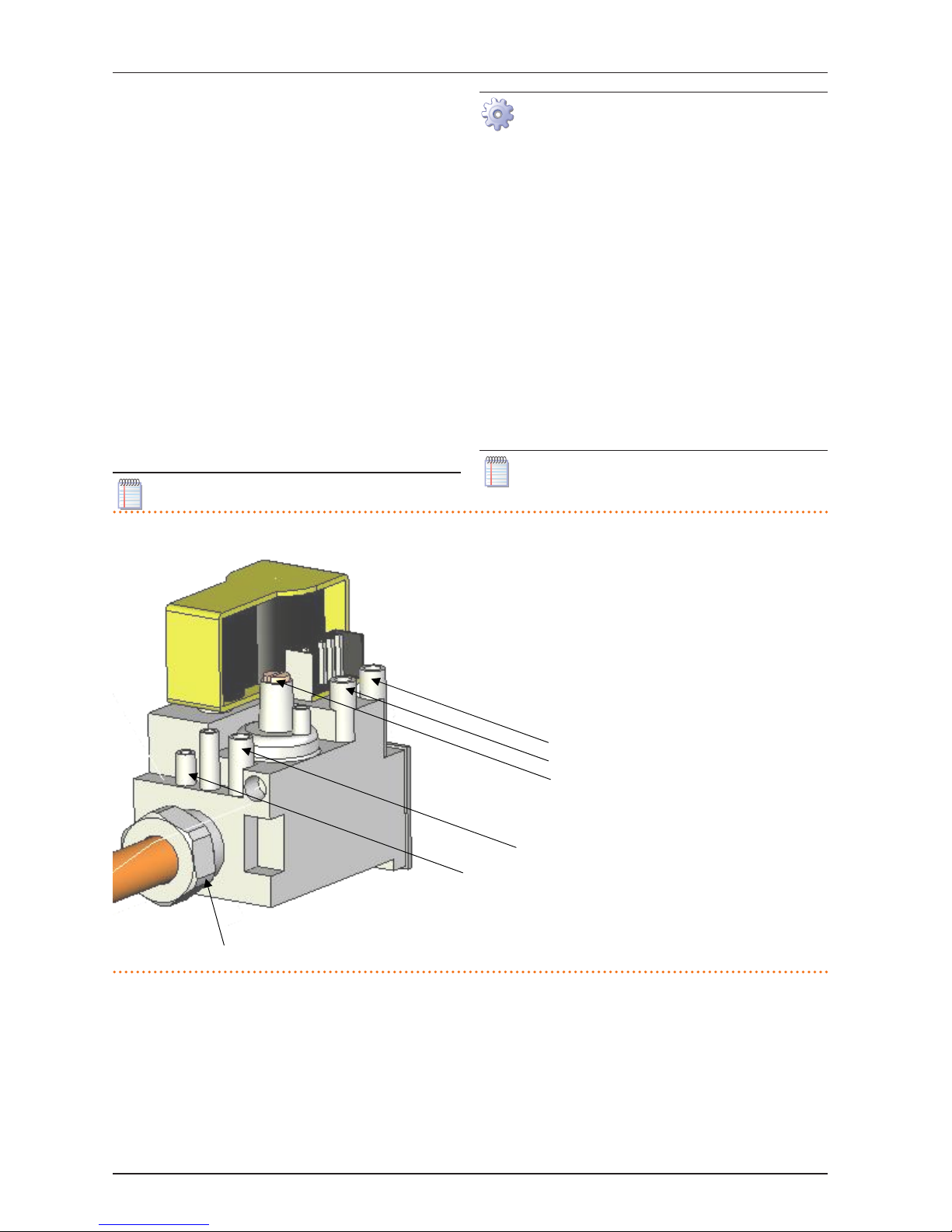
Figure 5.1p.27.
1. Start the appliance, setting external request so that it
enables operation; wait for the burner to start (green
light ON) (reference H in Figure 1.1p.8).
2. Force appliance operation to minimum thermal
power by acting on GHP10 board (menu 2, parameter 23).
3. Ensure the CO2 eading is between 8.2 – 8.6%. Otherwise set the CO2 percentage reading by acting on the
o set regulation screw.
4. Force appliance operation to maximum thermal
power (menu 2, parameter 24).
5. Ensure the CO2 reading is between 8.7 – 9.3%. Otherwise set the CO2 percentage reading by acting on the
throttle regulation screw.
6. Interrupt forced operation to maximum thermal
power (menu 2, parameter 25).
7. Let the appliance run until the water set point is
reached.
If the required CO2 setting cannot be reached contact
Robur.
Figure 5.1 – Gas valve
A
B
C
D
E
F
LEGEND
A Mains gas pressure
B O-set pressure
C O-set regulating screw
D Burner gas pressure
E Throttle regulating screw
F Nozzle
Page 28
5 First start-up
28
6 NORMAL OPERATION
This section is for the end user.
6.1 WARNINGS
General warnings
Prior to using the appliance carefully read the warnings
in Chapter III p. 4, providing important information
on regulations and on safety.
First start-up by TAC
First start-up may exclusively be carried out by a Robur
TAC (Chapter 5p.26).
Never power the appliance o while it is running
NEVER power the appliance o while it is running (except in the event of danger, Chapter III p. 4), since
the appliance or system might be damaged.
6.2 SWITCH ON AND OFF
Routine switching on/o
The appliance may exclusively be switched on/o
by means of the suitably provided control device
(OQLT017, OCDS005 or external request).
Do not Switch On/O with the power supply switch
Do not switch the appliance on/o with the power supply switch. This may be harmful and dangerous for the
appliance and for the system.
Inspections before switching on
Before switching on the appliance, ensue that:
▶
gas cock open;
▶
appliance electrical power supply (main switch (GS)
ON);
▶
OQLT017 or OCDS005 power supply (if present);
▶
water circuit ready.
How to switch on/o
▶
If the appliance is controlled by the OQLT017 controller
(system 1, see Paragraph 1.7 p. 14), refer to the relevant
manual.
▶
If the appliance is controlled by OCDS005 timer thermostat or external request (e.g. thermostat, timer, button, ...
with voltage-free NO contact), (systems (3) see Paragraph
1.7p.14), the appliance is switched on/o by the ON/OFF
positions of the external control device.
After switching on with the control, in normal operating conditions, the appliance starts/stops automatically according to the
user's thermal needs, supplying hot water at the programmed
temperature.
Although the external request is in the "ON" position,
this does not mean the appliance will start immediately, but it will only start when there are actual service
demands.
6.3 MESSAGES ON THE DISPLAY
4 digit display
The GHP10 board of the appliance (Paragraph 1.5p.13, Figure
1.7 p. 14) is tted with a 4-digit display, visible through the
sight glass of the front panel (reference L in Figure 1.1p.8).
▶
When the appliance is powered, all the LEDs switch on for
3 sec, then the GHP10 board name is displayed in two subsequent stages (GHP during the rst stage, 10 during the
second).
▶
After another 25 sec, the appliance is ready to operate.
Signals in normal operation
▶
During normal operation, water temperature values alternate on the display: output,input and the dierence between the two.
Signals in the event of fault
In the event of fault the display blinks indicating an operational
code (rst letter on the display: "E" = error, or "U" = warning)
▶
If it is only a temporary warning, the appliance may continue
working.
▶
If it is a permanent error or warning the appliance stops
For details on errors and warnings see Table 8.1p.34.
6.4 ONBOARD ELECTRONIC CONTROLS
MENUS AND PARAMETERS OF THE GHP10
BOARD
Firmware
The instructions on the use of the GHP10 electronic
board concern the rmware version 1.006.255.
The appliance's electronic board (GHP10)
Display
The 4-digit display of the S61 board (Detail A Figure 1.7p.14)
is as follows:
▶
the rst digit (on the left, green) indicates the menu number
(e.g. "0.", "1.", "2.", ... "8.");
▶
the last three digits (on the right, red) indicate a code or a parameter setting, among those included in the selected menu
(e.g. "__6" "_20", "161").
(e.g. menu+parameter "1.__6", "2._20", "3.161").
Selection keys
One of the following actions may be done with the GHP10 board
selection keys (references B and C in Figure1.7p.14):
▶
Enter the menu list (by pressing the Enter C key the rst
time);
▶
Scroll the menu list, or a series of parameters in a menu (by
pressing keys B <- ->).
▶
Select a menu or a parameter (pressing the key Enter C).
Page 29
5 First start-up
Installation, Use and Maintenance Manual – K18
29
▶
Edit and conrm the setting of a parameter (pressing keys B
<- -> and conrming with key Enter C).
▶
Execute a command (pressing key Enter C).
▶
Exit a menu and go back to the higher level by selecting the
letter “E” which is displayed at the end of the menu list or of
a series of parameters in a menu.
The letter "E" is displayed at the end of the menu list or of a series
of parameters in a menu, and indicates the exit to go back to the
higher level by pressing the knob.
Menus and Parameters
The menus may be display only (functional data or parameters),
display and setting (parameters) or control (reset).
▶
Display menus: menu "0" and menu "1";
▶
Control menu: menu "2" to execute error reset operations
(Paragraph 6.6p.32);
▶
Display and settings menu: menu "3" to display or set certain system parameters (e.g. water setpoint temperature);
the settings are initialised by the TAC upon First start-up; the
Table 6.1p.29 shows parameters in menu 3.
▶
Display and settings menu (to be exclusively used by the
installer and TAC): menu "4.", "5." and "6." They are password
protected. These are specic sections, exclusively intended
for skilled personnel (installer or TAC). For information see
the technical Assistant Manual.
How to access the Menus and Parameters
Before Starting:
(1) Power supply switch "ON";
(2) Display of the GHP10 board showing in sequence the
detected water temperature data (if the appliance is in
normal operation), or the blinking malfunction and failure codes (if the appliance is in failure).
To access the menus and parameters of the GHP10
board, proceed as follows (see also Figure 1.7p.14):
1. Remove the lower front panel by removing the xing
screws.
2. Press the Enter C key once to display the menus: the
rst menu is displayed, "0." (= menu 0).
3. Press the B -> key to scroll down and display the
other/subsequent menus; the menu numbers will be
displayed in order, "1.", "2.", ... , "6." ... or "E" (= exit).
4. Select the menu of interest (e.g. display "2.___" =
menu 2) by pressing the Enter C key; the rst parameter code will be displayed, in order in the menu (e.g.
display "2._21" = parameter 21 in menu 2).
5. Press the B -> key to scroll down the other parameters in the menu; the codes will be displayed in order
(e.g. display "2._21", ... "2._26" = parameters 21, ... 26
in menu 2), or letter "E" (= exit) at the end of the list.
6. Select the parameter of interest by pressing key Enter C; the display will show the setting previously
assigned to the parameter, read only or to be set; if
instead of a value/setting it is a command, a blinking
code is displayed (e.g. "Er1" for the board error reset
command).
7. Press the Enter C key to reconrm the gure; or use B
<- -> keys to modify the gure, and press Enter C at
the end to conrm or set the new gure; if however,
it is a matter of controlling an appliance operation,
press the Enter C key to execute it.
8. To exit a parameter menu or the menu list and go
back to the higher level, press the B -> key until displaying the letter "E" for exit, then press the Enter C
key again.
9. Fit the appliance's lower front panel again.
6.5 MODIFYING SETTINGS
Do not modify complex settings
Specic technical and system knowledge is required for
complex settings. Contact a TAC.
Table 6.1 – Menu 3 GHP10 board parameters
MENU 3 PARAMETERS
Parameter Description Setting
44 Temperature display format
0. °C (default)
1. °F
48 Building time constant from 0 to 50 hours (default 10 hours)
163 Anti-icing function
0. not active
1. active (default)
174 Circulation pump modulation (in heating mode)
0. not active
1. active (default)
175 Voltage (0-10V) for circulation pump o from 0 V to 10 V (default 0,7 V)
176
Voltage (0-10V) for circulation pump on in heating
mode (if circulation pump modulation is o, parameter
174=0)
from 0 V to 10 V (default 10 V)
177
Voltage (0-10V) for circulation pump on in DHW mode
(if circulation pump modulation is o, parameter
183=0)
from 0 V to 10 V (default 10 V)
178 Setpoint of water delta T (in heating mode) from +1°C to +20°C (default 10°C)
183 Circulation pump modulation (in DHW mode)
0. not active
1. active (default)
184 Setpoint of water delta T (in DHW mode) from +1°C to +20°C (default 10°C)
198 Fan noise reduction
0. not active (default)
1. active
225
(1)
Setpoint Origin
0. Fixed setpoint
1. Heating curve (default)
2. External setpoint
226
(1)
Fixed setpoint in heating operation
The minimum and maximum values depend on what
has been set in the installation stage.
Page 30
5 First start-up
30
227
(1)
Fixed setpoint in DHW operation from +10°C to +70°C (default 55°C)
228
(1)
Heating curve slope from 10 to 400 (default 75)
229
(1)
Heating curve oset from -5K to +5K (default 0)
230
(1)
Internal ambient setpoint with heating curve from 0°C to 40°C (default 20°C)
(1)
If the unit is connected to the OQLT017 controller this parameter is ignored.
How to set the heating curve
If the appliance is not connected to the OQLT017 system controller, follow the instructions below to set the
heating curve.
The heating curve makes it possible to change the system's outlet water temperature according to the measured external temperature and to the internal ambient set point temperature.
Depending on the type of installation, especially on the type of
exchangers (radiators, fan coils, oor radiators etc.) and the features of the building, a specic curve will be used, selected from
the family of heating curves. Furthermore, upon changing the
internal room set point temperature, the curve actually used will
be automatically modied.
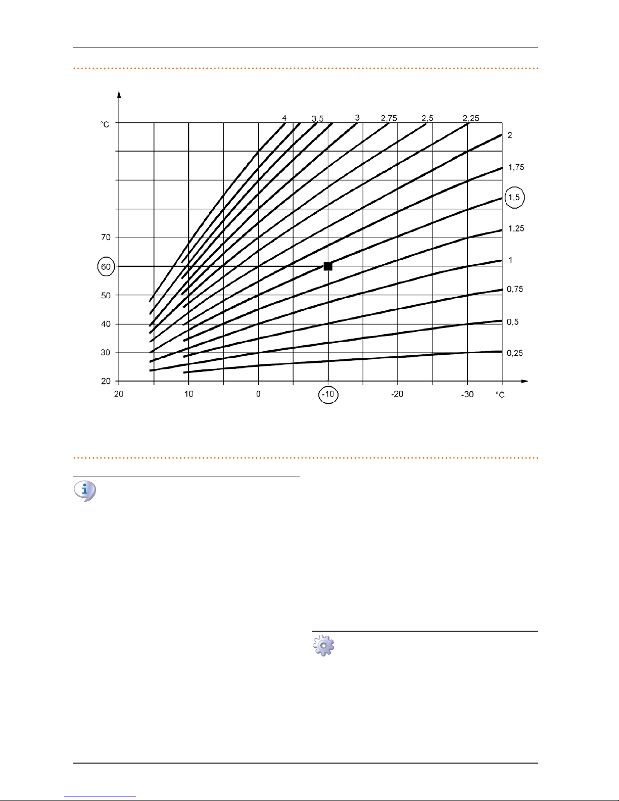
The family of heating curves is shown in Figure 6.1p.31 and
the curve to be used is chosen by specifying the value of parameter 228 in menu 3 which indicates the curve slope. The curve
dened in this way refers to an internal ambient set-point temperature of 20 °C (68 °F) . If the set-point temperature is dierent,
the system automatically adapts the curve used.
To set the adequate heating curve operate as specied
below:
1. set the ow water temperature according to the expected minimum external ambient temperature (for
instance: Twater = 60 °C when Toutside = -10 °C);
2. using the chart in Figure 6.1p.31, select the curve
that meets the above requirement (in the specic
case curve with slope 1.5);
3. multiply the slope of the selected curve by 100
and set the gure thus obtained in menu 3 parameter 228 (in the example set parameter 228 at 150);
If no curve passes through the established point, select
an intermediate gure between those of the curves
immediately above or immediately below this point.
Indicatively, a system that uses oor radiant heat exchangers will use "low" slope gures, a fan coil system
will use “medium” gures and a system with radiators
"high" gures.
4. Ensure parameter 229 (heating curve oset) is set at
0.
5. set parameter 230 (internal room setpoint with heating curve) at the desired setting (default setting
20°C).
Page 31
5 First start-up
Installation, Use and Maintenance Manual – K18
31
Figure 6.1 – Heating curves for internal ambient temperature = 20°C
Tamb
Tacq
LEGEND
Tacq water temperature
Tamb external ambient temperature
unit operation is based on the heating curve ONLY if the
setting of parameter 225 (menu 3) is at 1 (default setting
- see Table 6.1p.29).
If the slope of the selected curve is not correct the following
cases may occur, to be assessed during early operation of the
system:
▶
Ambient temperature lower when outdoor temperature is
lower: in this case, the slope of the curve is not sucient, it
is needed to set a higher value for parameter 228, indicating
the slope of the curve.
▶
Internal ambient temperature is higher when the external
temperature is lower: in this case the curve slope is excessive, a lower gure must be set for parameter 228 indicating
curve slope.
If however the slope is correct (stable internal ambient temperature when the outside temperature changes), but the internal
temperature does not match the set point one, the following
cases may occur:
▶
Internal ambient temperature is always higher than the setpoint: in this case one must act on the Oset parameter of
the heating curve, setting a negative gure equal to the internal temperature deviation from the setpoint; for instance,
if the setpoint is 22 °C and the actual internal temperature is
24 °C, set the Oset parameter (parameter 229) to -2 °C.
▶
Internal ambient temperature is always lower than the setpoint: in this case a positive gure must be set for the Oset
parameter of the heating curve; for instance, if the setpoint
is 20 °C and the actual internal temperature is 19 °C, set the
Oset parameter (parameter 229) to 1 °C.
How to raise/lower the water temperature set-point (xed
Setpoint)
The water temperature set-point establishes the outlet temperature to the system (water output from the appliance), or inlet
from the system (water input in the appliance). The temperature
is pre-set by the TAC upon First start-up
The water set point is set on outlet by default.
If the appliance is not connected to a OQLT017 system
controller, to raise/lower the water temperature setpoint with the GHP10 board, proceed as follows (also
see Paragraph 6.4p.28):
1. Access menu 3 under parameter 225 (= setpoint origin) with
keys Enter C and B <-->; set parameter 225 to 0 (xed setpoint - see Table 6.1p.29).
2. Set parameter 226 (xed setpoint in heating operation) to
the desired temperature setting.
3. Exit menu 3 by pressing the B -> key until displaying the letter "E" for exit, then press the Enter C key.
Page 32
7 Maintenance
32
How to modify the operation of the variable-ow circulation
pump
The C1 version (standard) is equipped with a variable-ow circulation pump.
The operation of the circulation pump is set by default as MODULATING (parameters 174 and 183 equal to 1) and with setpoint of water delta T equal to 10 °C (parameters 178 and 184 of
Table6.1p.29).
To modify the operation of the circulation pump, proceed as
follows:
1. Enter menu 3, parameters 174 and/or 183 (=circulation
pump modulation) through buttons Enter C and B <-->; set
value 0 (modulation deactivated – see Table 6.1p.29).
2. Set parameter 176 and/or parameter 177 (=voltage (0-10V)
for circulation pump on) to the correct value.
Parameters 176 and 177 are set by default to 10V (the
operation of the circulation pump is at maximum ow/
head and water delta T is low). To reduce the ow/head
and consequently increase the water delta T, set parameters 176 and 177 to a value lower than 10 V.
6.6 RESTARTING A LOCKEDOUT UNIT RESET
Fault signals on the display
In the event of locked-down appliance, an operational code
ashes on the display (rst green gure on the left, letter "U" =
warning or "E" = error).
▶
To restart the appliance you must know and perform the
procedure concerning the issue signalled and identied by
the code (Paragraph 8.1p.34).
▶
Only act if you are familiar with the issue and with the procedure (technical expertise and professional qualications
might be required).
▶
If you do not know the code, the problem, or the procedure,
or you do not have sucient skills, and in any case of doubt,
contact the TAC.
Locked-down appliance
An external intervention (reset or repair) is required due to an
appliance fault or problem with the system.
▶
A reset may be enough for a temporary and provisional
anomaly.
▶
For a fault or breakdown, alert the maintenance technician
or TAC.
Reset
There are three options for resetting a fault:
1. If the appliance is connected to the OQLT017 controller you
may act through the control device, as described in the relevant manual.
2. If a remote reset button has been provided (Paragraph
4.7p.26) act directly on the button.
3. One may act directly from the GHP10 board as described
below.
How to perform reset from the GHP10 board
To perform the reset directly from the GHP10 board:
1. Access Menu 2 under Parameter "_21", the display
must show "2._21" (procedure Paragraph 6.4p.28);
2. Press key Enter C: the display blinks "Er1".
3. To reset press key Enter C again.
4. Press key B -> scroll the menus "0.", "1.", "2."... until the
exit screen "E" is displayed and press the Enter C key
to conrm exit.
6.7 EFFICIENCY
For increased appliance eciency:
▶
Keep the nned coil clean;
▶
Set the maximum water temperature and heating curve at
the actual installation requirement;
▶
Reduce repeated switch-ons to the minimum (low loads);
▶
Program appliance activation for actual periods of use;
▶
Keep water and air lters on plumbing and ventilation systems clean.
7 MAINTENANCE
7.1 WARNINGS
Correct maintenance prevents problems, assures eciency and keeps running costs low.
Maintenance operations described herein may exclusively be performed by the TAC or skilled maintenance
technician.
Any operation on internal components may exclusively
be performed by the TAC.
Before performing any operation, switch o the appliance by means of the control device and wait for the
end of the switching o cycle, then disconnect power
and gas supply, by acting on the electrical disconnector
and gas cock.
The eciency checks and every other "check and
maintenance operation" (see Tables 7.1 p. 33 and
7.2 p. 33) must be performed with a frequency ac-
cording to current regulations or, if more restrictive, according to the provisions set forth by the manufacturer,
installer or TAC.
Responsibility for eciency checks, to be carried out for
the aims of reduction of energy consumption, lies with
the system manager.
Heavy-duty use
Page 33
7 Maintenance
Installation, Use and Maintenance Manual – K18
33
If the unit is subject to heavy duty use (for example
in process plants or in other conditions of continuous
operation), maintenance operations must be more
frequent.
7.2 PREEMPTIVE MAINTENANCE
▶
For pre-emptive maintenance, comply with the recommendations in the Table 7.1p.33
Table 7.1
GUIDELINES FOR THE PREVENTIVE MAINTENANCE OPERATIONS
Check of the unit
Visually check of the general condition of the unit and of its air heat exchanger.
(1)
Check the correct operation of the device used for monitoring the water ow
Check the % value of CO
2
Check that the condensate discharge is clean
[If necessary, frequency of the maintenace operation must be increased]
Replace the belts after 6 years or 12,000 hours of operation
(1) It is suggested to clean the nned coil once every 4 years [Optimal
frequency of the cleaning operation is in any case strongly aected by
the installation site].
7.3 SCHEDULED ROUTINE MAINTENANCE
▶
For scheduled routine maintenance, perform the operations
in Table 7.2p.33, at least once every 2 years.
Table 7.2
ROUTINE SCHEDULED MAINTENANCE (TO BE PERFORMED AT LEAST ONCE
EVERY TWO YEARS)
Check of the unit
Clean the combustion chamber*
Clean the burner*
Clean the electrodes of ignition and ame sensing
Check that the condensate discharge is clean
*Only in case the analysis of combustion products is non-compliant
7.4 PERIODS OF INACTIVITY
Avoid emptying the installation
Emptying the system may cause damage due to corro-
sion of the water pipes.
Deactivate the system in winter
Should you intend to stop the appliance in the winter
season, ensure at least one of the following conditions:
1. anti-icing function active (Paragraph 3.5p.19);
2. sucient anti-icing glycol (Paragraph 3.6p.19).
Prolonged periods of inactivity
▶
Should you foresee to leave the appliance inactive for a long
period of time, disconnect it from the electrical and gas
mains. These operations must be performed by Qualied
Personnel.
How to deactivate the appliance for long periods of
time
1. Switch the appliance o (6.2p.28).
2. Only when the appliance is completely o, power it
o with the main switch/disconnector switch (Detail
GS in Figure 4.2p.).
3. Close the gas valve
4. If necessary, add water with glycol (if the appliance
is disconnected from the power and gas mains, the
active anti-icing protection is missing, Paragraph
3.5p.19).
How to reactivate the appliance after long periods of
inactivity
Before reactivating the appliance, the operator/maintenance technician of the system must rst of all:
▶
Check whether any maintenance operations are required (contact the TAC; see Paragraphs 7.2 p. 33
and 7.3p.33).
▶
Check content and quality of the water in the system,
and if necessary top it up (Paragraphs 3.8 p. 20,
3.7p.20 and 3.6p.19 ).
▶
Ensure the ue gas exhaust duct is not obstructed,
and that the condensate drain is clean.
After completing the above checks:
1. Open the gas cock and ensure there are no leaks;
should gas smell be noticed, close the gas cock
again, do not switch any electrical devices on and
request intervention by Skilled Personnel.
2. Power on with the main power supply switch (GS,
Figure 4.2p.).
3. Switch on the appliance using the control device
provided.
Page 34
7 Maintenance
34
8 DIAGNOSTICS
8.1 OPERATIVE CODES
Table 8.1 – Operative Codes
CODES DESCRIPTION Warning (u) Error (E)
401
GENERATOR LIMIT THERMOSTAT
TRIP
NA Contact authorised Technical Assistance
402 FLUE GAS THERMOSTAT TRIP Contact authorised Technical Assistance
405
AMBIENT TEMPERATURE EXCEEDING OPERATIVE LIMITS
NA Reset is automatic when the triggering condition ceases.
406
AMBIENT TEMPERATURE LOWER
THAN OPERATIVE LIMITS
Non-blocking Warning (informative code).
The code is reset automatically when the trigger-
ing condition ceases.
NA
407 GENERATOR TEMPERATURE HIGH
Reset is automatic when the triggering condition
ceases.
Reset may be performed from the GHP10 board (menu 2, parameter 21).
If the code persists, shows up again or in case of doubt, contact
the TAC.
408 FLAME ON WITH LOCK-OUT NA Contact authorised Technical Assistance
410 INSUFFICIENT WATER FLOW
Reset is automatic when the triggering condition
ceases.
Check and clean water lters on the system.
Check for air in the system.
Check water ow pump.
Power cycle the appliance.
Reset may be performed from the GHP10 board (menu 2, parameter 21).
If the code persists, shows up again or in case of doubt, contact
the TAC.
411
INSUFFICIENT ROTATION OF OIL
PUMP
Reset occurs automatically 20 minutes after the
code is generated.
Reset may be performed from the GHP10 board (menu 2, parameter 21).
If the code persists, shows up again or in case of doubt, contact
the TAC.
412 FLAME CONTROLLER UNIT ARREST
Reset is automatic up to 4 attempts (in about 5
minutes).
Gas supply check.
Reset may be performed from the GHP10 board (menu 2, parameter 21).
If the code persists or in case of doubt, contact the TAC.
413
FLAME CONTROLLER COMMUNICATION ERROR
Reset is automatic when the triggering condition
ceases.
Reset may be performed from the GHP10 board (menu 2, parameter 21).
If the code persists, shows up again or in case of doubt, contact
the TAC.
414
FLAME CONTROLLER NOT
COMPATIBLE
NA Contact authorised Technical Assistance
415
FLAME CONTROLLER PARAMETERS
ERROR
NA Contact authorised Technical Assistance
416
FAULTY HOT OUTLET WATER TEMPERATURE PROBE
NA
Reset may be performed from the GHP10 board (menu 2, parameter 21).
If the code persists, shows up again or in case of doubt, contact
the TAC.
417
FAULTY HOT OUTLET WATER
INLET TEMPERATURE PROBE
NA
Reset may be performed from the GHP10 board (menu 2, parameter 21).
If the code persists, shows up again or in case of doubt, contact
the TAC.
420
FAULTY GENERATOR TEMPERATURE
PROBE
NA
Reset may be performed from the GHP10 board (menu 2, parameter 21).
If the code persists, shows up again or in case of doubt, contact
the TAC.
422 FAULTY WATER FLOWMETER NA
Reset may be performed from the GHP10 board (menu 2, parameter 21).
If the code persists, shows up again or in case of doubt, contact
the TAC.
424
FUMES TEMPERATURE SENSOR
FAU LT
NA
Reset may be performed from the GHP10 board (menu 2, parameter 21).
If the code persists, shows up again or in case of doubt, contact
the TAC.
425
CONDENSATE DISCHARGE
CLOGGED
NA
Check and clean condensate discharge.
Reset may be performed from the GHP10 board (menu 2, parameter 21).
If the code persists, shows up again or in case of doubt, contact
the TAC.
426
GENERATOR FIN TEMPERATURE
SENSOR MALFUNCTION
NA
Reset may be performed from the GHP10 board (menu 2, parameter 21).
If the code persists, shows up again or in case of doubt, contact
the TAC.
430 HIGH FIN TEMPERATURE
Reset is automatic when the triggering condition
ceases.
Reset may be performed from the GHP10 board (menu 2, parameter 21).
If the code persists, shows up again or in case of doubt, contact
the TAC.
Page 35

7 Maintenance
Installation, Use and Maintenance Manual – K18
35
CODES DESCRIPTION Warning (u) Error (E)
436 BLOWER FAULT
Reset occurs automatically 20 minutes after the
code is generated.
Reset may be performed from the GHP10 board (menu 2, parameter 21).
If the code persists, shows up again or in case of doubt, contact
the TAC.
438
INTERNAL FLAME CONTROLLER
ERROR
Reset occurs automatically 10 seconds after the
code is generated.
Reset may be performed from the GHP10 board (menu 2, parameter 21).
If the code persists, shows up again or in case of doubt, contact
the TAC.
439 FAULTY FAN
Reset is automatic when the triggering condition
ceases.
NA
440 FAULTY OIL PUMP INVERTER
Reset is automatic when the triggering condition
ceases.
NA
441 FALSE FLAME NA
Reset may be performed from the GHP10 board (menu 2, parameter 21).
If the code persists, shows up again or in case of doubt, contact
the TAC.
442 FLAME LOSS
Reset occurs automatically 10 seconds after the
code is generated.
NA
443
LACK OF COMMUNICATION BETWEEN FLAME CONTROLLER AND
BOARD
Reset is automatic when the triggering condition
ceases.
Reset may be performed from the GHP10 board (menu 2, parameter 21).
If the code persists, shows up again or in case of doubt, contact
the TAC.
444
FAULTY EVAPORATOR TEMPERATURE PROBE
NA
Reset may be performed from the GHP10 board (menu 2, parameter 21).
If the code persists, shows up again or in case of doubt, contact
the TAC.
446
HIGH HOT INLET WATER
TEMPERATURE
Check conguration of other heat generators on
the system.
Ensure the secondary circuit pump is working.
Ensure the exchange terminals are active.
Check any by-passes between outlet and inlet.
Reset is automatic and occurs if the generating
condition ceases with circulating pump on or 20
minutes after the code is generated with circulating pump o.
NA
447
HOT INLET WATER TEMPERATURE
LOWER THAN OPERATIVE LIMITS
Reset occurs automatically when the generating
cause resolves or 430 seconds after the code is
generated.
Reset occurs automatically when the condition that generated the
code ceases.
If the code shows up again or in case of doubt contact the TAC.
448
HIGH HOT WATER DIFFERENTIAL
TEMPERATURE
Check cleanliness of water lters.
Check water ow.
Reset occurs automatically 20 minutes after the
code is generated.
Reset occurs automatically when the condition that generated the
code ceases.
If the code shows up again or in case of doubt contact the TAC.
452 DEFROSTING FUNCTION ACTIVATED
Non-blocking Warning (informative code).
The code clears automatically when execution of
defrosting ends.
NA
453
WATER FLOW PASSIVE HOT
MODULE
Reset is automatic when the triggering condition
ceases.
NA
474
FAULTY MANIFOLD EXTERNAL
PROBE
Reset is automatic when the triggering condition
ceases.
NA
478
HIGH HOT OUTLET WATER
TEMPERATURE
Check cleanliness of water lters.
Check water ow.
Reset is automatic when the triggering condition
ceases.
NA
479 DEFROST FUNCTION ACTIVATED
Non-blocking Warning (informative code).
The code clears automatically when anti-icing
function execution ends.
NA
80/480
INCOMPLETE OR INVALID
PARAMETERS
Contact authorised Technical Assistance.
481 INVALID P0 PARAMETERS
Reset is automatic when the triggering condition
ceases.
Contact authorised Technical Assistance.
482 INVALID P1 PARAMETERS
Reset is automatic when the triggering condition
ceases.
Contact authorised Technical Assistance.
485 INCORRECT MODULE TYPES NA Contact authorised Technical Assistance.
486 FAULTY BOARD, ROM NA Contact authorised Technical Assistance.
487 FAULTY BOARD, pRAM NA Contact authorised Technical Assistance.
488 FAULTY BOARD, xRAM NA Contact authorised Technical Assistance.
489 FAULTY BOARD, REG. NA Contact authorised Technical Assistance.
490
FAULTY AMBIENT TEMPERATURE
PROBE
NA
Reset may be performed from the DDC/CCI or from the S61 board
(menu 2, parameter 21).
If the code persists, shows up again or in case of doubt, contact
the TAC.
491 CONTROLLER DEFECTIVE NA Contact authorised Technical Assistance.
492 FAULTY EXTERNAL ROOM PROBE
Reset is automatic when the triggering condition
ceases.
NA
NA: Not Applicable
Page 36
Appendices
36
APPENDICES
1 DECLARATION OF CONFORMITY
Figure 1
coscienza ecologica caring for the environment
Robur S.p.A. tecnologie avanzate per la climatizzazione advanced heating and cooling technologies www.robur.it [email protected]
via Parigi 4/6 24040 Verdellino/Zingonia (BG) Italy T +39 035 888111 F +39 035 884165 capitale sociale € 2.028.000,00 i.v. iscritta al Registro
Imprese di Bergamo n. 154968 codice fiscale/partita iva 00373210160 V.A.T. code IT 00373210160 società soggetta all’attività di direzione e
coordinamento di Fin Robur S.a.p.A. di Benito Guerra & C.
EC – DECLARATION OF CONFORMITY
Manufacturer : Robur S.p.A.
Address : Via Parigi 4/6
City, Country : Verdellino/Zingonia 24040 (Bg), Italy
This is to declare that the ROBUR Gas Absortion Heat Pump (GAHP) are in conformity with the following ECDirectives:
2006/42/EC
Machinery Directive with subsequent amendments and integrations.
2004/108/EC Electromagnetic Compatibility with subsequent amendments and integrations.
Tested and examined according to the following norms: EN55014-1, EN55014-2, EN61000-3-2, EN61000-3-3,
EN62233.
2006/95/EC Low Voltage Directive with subsequent amendments and integrations.
Tested and examined according to the following norms: EN50165, EN60335-2-102, EN60335-1.
2009/142/EC Gas Appliance Directive with subsequent amendments and integrations.
Tested and examined according to the following norms: EN 12309-1. EN 12309-2, EN 483.
As proved whit EC certification number 0964, issued by KIWA Italia S.p.A Via G. Carducci,5 Milan-Italy
97/23/EC Pressure Equipment Directive with subsequent amendments and integrations.
As proved with EC Certification number 1370 of all the components under pressure of the III° category,
issued by BUREAU VERITAS Italia S.p.A. Via Miramare, 15 Milan-Italy
Jvan Benzoni
R&D Director
Robur S.p.A.
Page 37

Page 38

Page 39

Page 40
Robur mission
Robur Spa
advanced climate
control technologies
Via Parigi 4/6
24040 Verdellino/Zingonia (Bg) Italy
T +39 035 888111⇒F +39 035 884165
www.robur.it [email protected]
Robur is dedicated to dynamic progression
in research, development and promotion
of safe, environmentally-friendly, energy-eciency products,
through the commitment and caring
of its employees and partners.
Revision: A - 3.1 Code: D-LBR687 09/07/2015
 Loading...