

Page 1
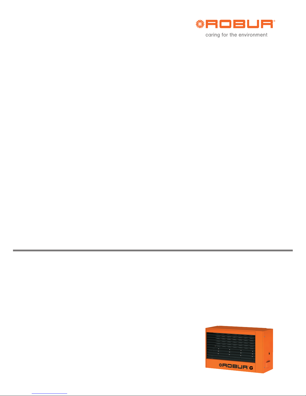
Gas unit heaters product line
G Series
Condensing and modulating Gas Fired Unit Heaters
to heat medium large areas
Natur
al gas/
LP
G fired
Installation, use and
maintenance manual
Page 2

EDITION: 09/2018
Code: D-LBR565
This manual has been written and printed by Robur S.p.A.; the reproduction even partial
of this manual is forbidden.
The original is archived at Robur S.p.A.
Any use of this manual other than for personal consultation must b e previously authorised
by Robur S.p.A.
The rights of those who have legitimately filed the registered trademarks contained within
this publication are not affected.
With the aim of continuously improving the quality of our products, Robur S.p.A. reserves
the right to modify instructions, drawings and data contained in this manual without prior
notice.
Page 3
Condensing Gas Fired Unit Heaters – G Series: Manual of installation, use and maintenance
Ed. 09/2018 I
FOREWORD
This manual is intended for those people who need to install and use the Robur G Series
condensing Gas Fired Unit Heaters.
In particular this manual is addressed to the hydraulic installation technician who shall
install the generator, the electrical installation technician who shall connect the generator
to the power supply and the final user who shall check its normal working. This manual is
also addressed to the Technical Assistance Centres for the main service operations.
Summary
This manual is based on five sectio ns
Section 1 is intended for end user, plumber installer , electrical installer and technical
assistance service; it furnishes general instructions, technical data and general
information of the Gas Fired Uni t Heat er s G series.
Section 2 is intended for end user; it furnishes all information for the correct use of Gas
Fired Unit Heaters G series.
Section 3 is intended for the plumber installer; it furnishes the information for a correct
installation of Gas Fired Unit Heaters G series.
Section 4 is intended for electrical installer; it furnishes the information for correct
electrical connections of the Gas Fired Unit Heaters G series.
Section 5 is intended for technical assistance service; it furnishes the instructions to set
the gas flow and to change the type of gas. It reports also information about maintenance.
Meaning of Icons
The icons placed on the margin of the pages of this manual have the following meaning:
Danger signal
Warning
Note
Start of operating procedure
Reference to another part of the manual or to another
manual/book
Table 1 – Descriptive Icons.
Page 4

Condensing Gas Fired Unit Heaters – G Series: Manual of installation, use and maintenance
Ed. 09/2018 1
TABLE OF CONTENTS
Section1: GENERAL INFORMATION AND TECHNICAL CHARACTERISTICS ..............2
1.1 GENERAL WARNINGS .....................................................................................................................2
1.2 OPERATION OF THE UNIT ..............................................................................................................3
1.3 CONSTRUCTIVE CHARACTERISTICS ............................................................................................5
1.4 TECHNICAL DATA ............................................................................................................................6
1.5 DIMENSIONS OF G SERIES GAS FIRED UNIT HEATER ...............................................................7
section 2: END USER ........................................................................................................9
2.1 FUNCTIONS OF CHRONOTHERMOSTAT ......................................................................................9
2.2 SETTING THE TIME AND DAY ON THE CHRONOTHERMOSTAT ............................................. 10
2.3 SETTING THE COMFORT, ECONOMY AND ANTI- FREEZING TEMPERATURES ON THE
CHRONOTHERMOSTAT ............................................................................................................... 10
2.4 PROGRAMMING OF THE DAILY SET POINT ON THE CHRONOTHERMOSTAT ...................... 11
2.5 SELECTING A PRESET DAILY PROFILE ON THE CHRONOTHERMOSTAT ............................ 13
2.6 SELECTING A PRESET WEEKLY PROFILE ON THE CHRONOTHERMOSTAT ........................ 13
2.7 TIMED FUNCTIONS OF THE CHRONOTHERMOSTAT ............................................................... 15
2.8 KEYBOARD BLOCK ....................................................................................................................... 17
2.9 INFORMATION SCREEN OF THE CHRONOTHERMOSTAT ....................................................... 18
2.10 SELECTION MENU WINDOW ....................................................................................................... 19
2.11 MALFUNCTION WARNINGS ......................................................................................................... 20
2.12 TABLE OF ICON MEANINGS ON CHRONOTHERMOSTAT DISPLAY ........................................ 22
2.13 HOW TO USE THE UNIT HEATER ................................................................................................ 23
2.14 HOW TO USE THE UNIT WITH THE CHRONOTHERMOSTAT .................................................. 25
2.15 HOW TO USE THE UNIT WITHOUT A CHRONOTHERMOSTAT ................................................ 30
2.16 SETTING FIELD.............................................................................................................................. 31
2.17 END OF SEASON ........................................................................................................................... 32
section 3: PLUMBER INSTALLER .................................................................................. 33
3.1 GENERAL RULES FOR INSTALLATION OF THE APPLIANCE ................................................... 33
3.2 INSTALLATION SEQUENCE ......................................................................................................... 33
3.3 SIZE AND INSTALLATION OF THE AIR INLET / EXHAUST FLUE .............................................. 35
3.4 CONDENSATE DRAINAGE ........................................................................................................... 44
section 4: ELECTRICAL INSTALLER ............................................................................. 46
4.1 HOW TO CONNECT THE HEATER TO THE ELECTRICAL SYSTEM ......................................... 46
4.2 HOW TO CONNECT THE CHRONOTHERMOSTAT TO THE HEATER ...................................... 46
4.3 UNIT OPERATION WITH EXTERNAL CONSENT ......................................................................... 47
4.4 REMOTE SIGNALLING OF THE ANOMALIES .............................................................................. 48
4.5 INSTALLATION WIRING DIAGRAM .............................................................................................. 49
4.6 WIRING DIAGRAM FOR MULTIPLE HEATER WITH ONE PROGRAMMER ............................... 50
section 5: ASSISTANCE AND MAINTENANCE ............................................................. 52
5.1 START UP OF THE UNIT ............................................................................................................... 52
5.2 HOW TO REGULATE THE GAS VALVE ....................................................................................... 52
5.3 CONVERSION TO ANOTHER TYPE OF GAS .............................................................................. 54
5.4 MAINTENANCE .............................................................................................................................. 55
Page 5
Condensing Gas Fired Unit Heaters – G Series: Manual of installation, use and maintenance
2 Ed. 09/2018
SECTION1: GENERAL INFORMATION AND TECHNICAL
CHARACTERISTICS
In this section you can find the general warnings to follow for the installation and use of
the Condensing Gas Fired Unit Heaters G Series, a short description of the heater
operation, design characteristics and technical data.
1.1 GENERAL WARNINGS
This manual is an integral and essential part of the product and must be given to the final
user.
This appliance must be exclusively used for the purpose it was intended. Any other use is
to be considered improper and therefore dangerous.
The unit must not be used by persons (children included) with lack of physical or mental
disease or not experienced. Children must be supervised to be sure that they do not
play with the unit.
The Manufacturer will not be held responsible for damages resulting from installation
errors or failure to comply with the Manufacturer’s instructions.
The appliance must be installed in compliance with the rules and regulations in force.
Do not obstruct the fan intake opening or the air delivery grids.
In case of failure and/or malfunction of the appliance, isolate the unit (disconnect it
from the power supply and close the main gas cock), do not attempt any repair or
direct servicing.
The Manufacturer’s Authorised Service Centres using only original spare parts
must only carry out any repair to the products.
The non-observance of the above-mentioned provisions may compromise the safety of
the unit.
To ensure unit efficiency and correct operation, it is essential that qualif ied service
engineers carry out annual maintenance following the Manufacturer’s instructions.
By the term Qualifi ed Ser v ic e Engi ne er s i t is mea nt t he pers o nnel h aving specific
technical skills in the field of heating system components for civil use. In any case for
more information please contact the Technical Assistance Office of ROBUR S.p.A.
(tel. +39 035/888111).
Should the unit be sold or transferred to another owner, please ensure that the manual
remains with the unit for use by the new owner and/or installer.
Before turning the heater on, a quali f ied ser v ice en g ineer must check:
- that electric and gas supply ratings are the same as those given in the data plate;
- that the exhaust duct operates correctly;
- the correct functioning of the condensate drainage;
- that combustion air feed and exhaust occur correctly according to the existing
standards;
Page 6
Condensing Gas Fired Unit Heaters – G Series: Manual of installation, use and maintenance
Ed. 09/2018 3
- the internal and external tightness of the fuel suppl y system;
- fuel flow control accordi ng to the heater power requirements;
- that the heater is supplied with the type of fuel for which it is pre-set.;
- that the gas supply pressure is within rating limits;
- that the gas supply system is suitable to the heater and all safety and check-over
devices prescribed by existing standards ar e dul y installed;
Do not use gas pipes to ground the appliance, or any other electrical appliances.
Avoid unnecessary supply when unit is not in use and always clock the main gas
cock. If the appliance is turned off for a longer time period, close the main gas
supply cock and cut off the power supply.
IF YOU SMELL GAS
• Do not operate electric switches, telephones and any other object or device
which may cause sparks.
• Shut-off the gas supply.
• Open immediately doors and windows to create a cross-current of air to purify
the room.
• Call for a qualified service engineer.
1.2 OPERATION OF THE UNIT
The G Series gas fired unit heater is an independent heater appliance with airtight
combustion circuit and forced air draft.
It is designed for an indoor installation - inside the area to be heated.
It is adjustable for the use of Natural Gas (G20) and L.P.G. (G30/G31) (appliance
belonging to the II
2H3B/P
category according to the Standard EN 1020).
The combus tion circuit is airtight with respect for the heated environment and conforms to
the ordinances of regulat ions EN 1020 and EN 1196 for C type appli ances : the air inlet of
the combustion air and the flue exhaust are outdoors and are ensured through the
operation of combustion blower.
A room thermostat, integrated in a chronothermostat, controls the heater operation.
When the thermostat is turned on the flame control box, after the pre-purge period (about
40 seconds), ignites the burner.
The flame sensor controls the ignition of the burner. If the flame does not appear the
flame control unit locks out the heater.
The combustion products pass through the heat exchangers, the air flow given by the
axial fan provides warm air to the room.
The airflow direction is regulated by means of adjustable horizontal louvres.
The fan control thermostat allows the axial-flow fan to start automatically only when the
heat exchangers are hot (after about 60 sec. from the flame detection or when the
temperature of 60°C is reached on the exchanger thermostat) and to turn off when they
are cold. This prevents cool air from being blown into the room.
Page 7

Condensing Gas Fired Unit Heaters – G Series: Manual of installation, use and maintenance
4 Ed. 09/2018
If heat exchangers overheat due to malfunction, the temperature limit thermostat cuts off
the supply to the gas valve by setting the blower and the fan to the maximum speed;
should the temperature increase further, the limit thermostat comes into operation causing
the switching off of the heater. The limit thermostat reset is manual.
After removing the cause of overheating, Qualified service engineers should carry
out resetting of the temperature.
Ahead of the burner the flue fan is installed which makes the air-gas mixture and forces
draft of the exhaust flues.
In case of obstructions in the exhaust or intake duct or in case of blower malfunction, the
flame control box intervenes immediately with the modulation of the heater. In case of
obstructions or malfunction beyond the allowed limits, the differential pressure switch
closes the gas valve and consequently stops the fuel flow to the burner.
For winter operation the heating unit can be used in either automatic or manual mode. For
further information see paragraph “WINTER OPERATING (HEATING)” at page 25.
In the summer time it is possible to activate only the axial fan to provide pleasant and
refreshing air movement in the room (for more information see Paragraph “SUMMER
OPERATION (VENTILATION ONLY)” at page 29).
Page 8

Condensing Gas Fired Unit Heaters – G Series: Manual of installation, use and maintenance
Ed. 09/2018 5
1.3 CONSTRUCTIVE CHARACTERISTICS
The G Series gas fired unit heaters are supplied with:
• Premix burner made of stainless steel.
• High head blower, with rotation speed control.
• Cylindrical combustion chamber made of stainless steel.
• Heat exchangers, patented by ROBUR, made of special light alloy, fining horizontally
on the air side and vertically on the flue side with extremely high capacity of thermal
exchange.
• Steel casing painted w it h epoxy powders.
• High air flow capacity axial fan(s), with rotation speed control.
• SAFETY AND CONTROL DEVICES
Programming electronic board, with microprocessor and filter: it allows the
following functions: start up of the burner, check and modulation of the flame; set
and control of the blower speed, set speed of fan(s); control of the temperature of
the heat exchanger by a probe; control o f the mini m um te mp erat ur e o f the
exhaust flue by a probe.
• Supply voltage: 230 V - 50 Hz.
• Safety time: 5 seconds.
• Pre- purge time: 40 seconds.
• Model: Bertelli & Partners DIMS03 with ignition
transformer BRAHMA TC2LTCAF.
Limit thermostat 100°C preventing the overheating of the heat exchanger.
Exhaust flue thermostat: in case the exhaust/air intake pipe or the internal
condensing discharge pipe would be obstructed the unit will stop.
Gas valve: in the case that one of the safety devices is activated (limit thermostat,
safety thermostat, etc.) the gas valve is electrically de-energised with
contemporary cut-off of the burner gas supply.
• Supply voltage: 230 V - 50 Hz.
• Operating temperature: 0° C up to +60° C.
• Model: SIT 822 Novamix.
Page 9
Condensing Gas Fired Unit Heaters – G Series: Manual of installation, use and maintenance
6 Ed. 09/2018
1.4 TECHNICAL DATA
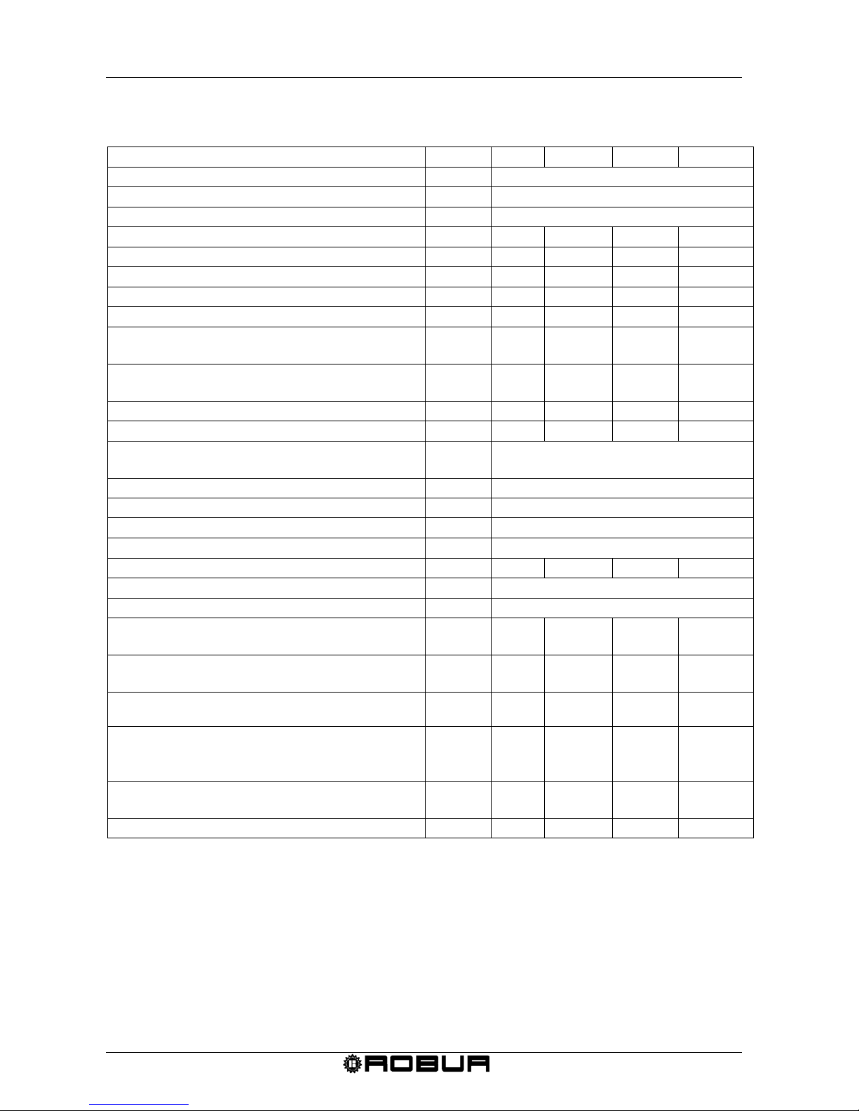
MODEL U.M. G 30 G 45 G 60 G 100
APPLIANCE CATEGORY II
2H3P
APPLIANCE TYPE C13 - C33 – B23 - C63 - C
53
GAS SUPPLY Gas naturale - G.P.L.
NOMINAL HEAT INPUT (Hi)
kW
30
45
58
93
NOMINAL HEAT OUTPUT kW 29,2 43,3 56,2 90,2
MINIMUM HEAT INPUT (Hi) kW 15,0 15,0 19,3 31,7
MINIMUM HEAT OUTPUT kW 15,8 15,6 20,2 33,5
MAX CONDENSATE PRODUCED l/h 4,6 6,9 8,9 14,4
NOMINAL GAS CONSUMPTION (Hi) NATURAL GAS
(15° C – 1013 mbar) L.P.G.G31
m3/h
kg/h
3,17
2,33
4,76
3,50
6,14
4,50
9,84
7,22
ECONOMY GAS CONSUMPTION (Hi) NATURAL GAS
(15° C – 1013 mbar) L.P.G.G31
m3/h
kg/h
1,58
1,16
1,58
1,16
2,14
1,50
3,35
2,46
EFFICIENCY AT MAXIMUM HEAT INPUT % 97,3 96,5 97 97
EFFICIENCY AT THE MINIMUM HEAT INPUT % 105,3 104,3 104,6 105,7
INLET GAS PRESSURE NATURAL GAS
L.P.G.G31
mbar
20
37
DIAMETER GAS INLET ” 3/4
AIR INLET PIPE DIAMETER mm 80
EXHAUST FLUE DIAMETER mm 80
VOLTAGE
230V - 50Hz
WATTAGE W 210 330 580 1000
OPERATIONAL TEMPERATURE
(1)
IN AMBIENT ºC 0 +35
FUSE A 6,3
AIR FLOW
(2)
AT MAXIMUM SPEED
AT MINIMUM SPEED
m3/h
2840
2050
3850
2900
5050
4000
8250
5200
TEMPERATURE RISE AT MAXIMUM SPEED
AT MINIMUM SPEED
K
29
22
32
15
32
14
31
18
THROW AT THE MAX SPEED
(RESIDUAL AIR SPEED >1m/s)
(3)
m 18 25 31 40
NOISE LEVEL AT 6 METERS
(MAX SPEED) IN FREE FIELD
IN TYPICAL INSTALLATION
dB(A)
dB(A)
48,5
55,5
55
62
59
66
59
66
NOISE LEVEL AT 6 M DISTANCE
(MAX SPEED) IN TYPICAL INSTALLATION dB(A) 50 56 60 60
WEIGHT kg 55 65 75 120
Table 2 – Technical data.
1 OPERATIONAL TEMPERATURE OF THE COMPONENTS ON THE APPLIANCE is between 0 °C / +60 °C.
2 AT 20 ° C – 1013 mbar.
3 VALUES MEASURED IN FREE FIELD; IN TYPICAL INSTALLATION THE HEAT FLOW COULD REACH BIGGER DISTANCES THA N
THE VALUE INDICATED (DEPENDING ON THE HEIGHT OF THE BUILDING AND THERMAL INSULATIO N OF THE ROOF).
Page 10
Condensing Gas Fired Unit Heaters – G Series: Manual of installation, use and maintenance
Ed. 09/2018 7
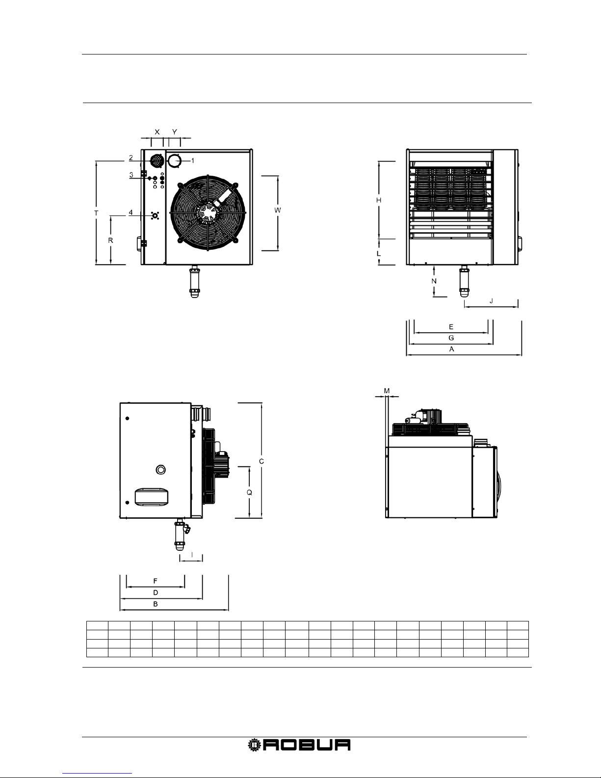
1.5 DIMENSIONS OF G SERIES GAS FIRED UNIT HEATER
Figure 1 – Dimensions of gas fired unit heater model G 30 – G 45 – G 60.
A B C D E F G H I J L M N Q R T W X Y
G 30
656
710
800
570
370
405
440
536
157,2
307
180
20
223
360
340
720
380
80
80
G 45
706
715
800
570
370
405
490
536
157,2
327
180
20
223
360
340
720
480
80
80
G 60
796
720
800
570
510
405
580
536
157,2
371
180
20
223
360
340
720
500
80
80
LEGEND
1
flue exhaust
2
combustion air
3
power line
4
gas connection
REAR VIEW
FRONT VIEW
SIDE VIEW
TOP VIEW
Page 11
Condensing Gas Fired Unit Heaters – G Series: Manual of installation, use and maintenance
8 Ed. 09/2018
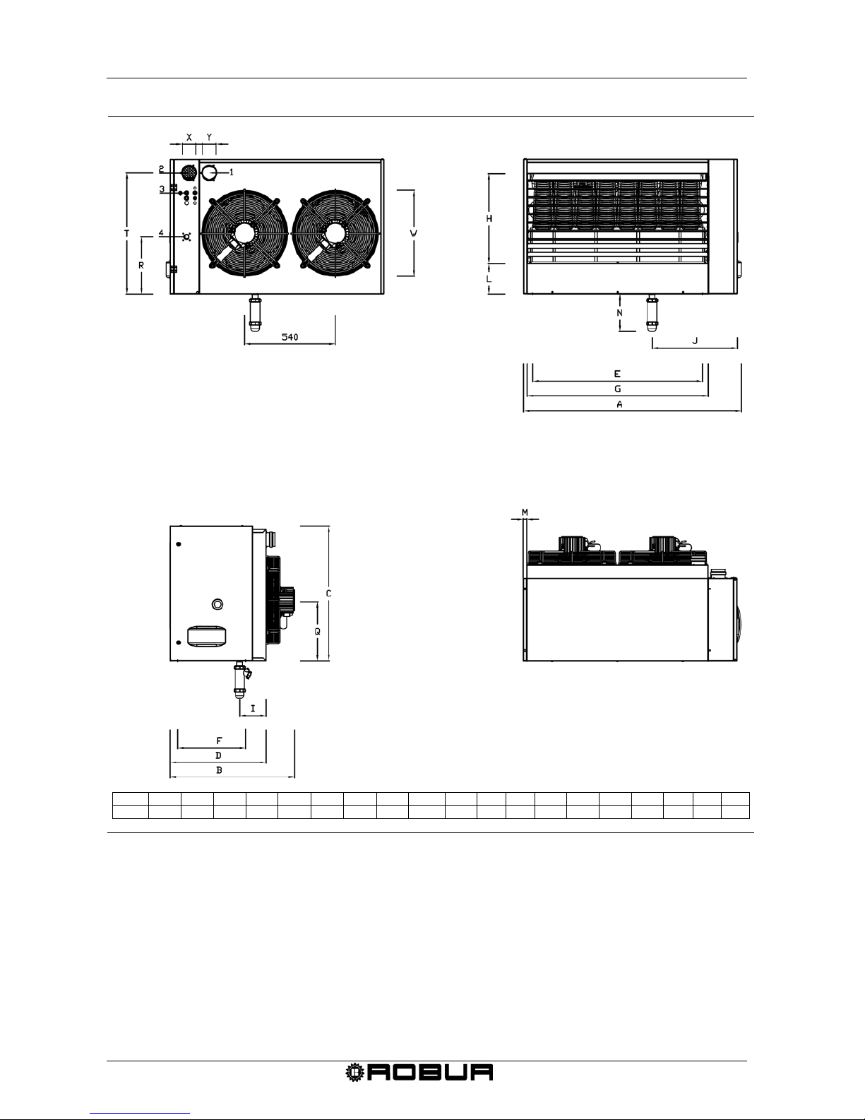
Figure 2 – Dimensions of gas fired unit heater model G 100.
LEGEND
1
flue exhaust
2
combustion air
3
power line
4
gas connection
A B C D E F G H I J L M N Q R T W X Y
G 100
1296
740
800
570
1010
405
1080
536
157,20
507
180
20
223
360
340
720
520
80
80
FRONT VIEW
REAR VIEW
SIDE VIEW
TOP VIEW
Page 12
Condensing Gas Fired Unit Heaters – G Series: Manual of installation, use and maintenance
Ed. 09/2018 9
SECTION 2: END USER
In this section you will find all the information necessary for the correct use of the G series
heating units.
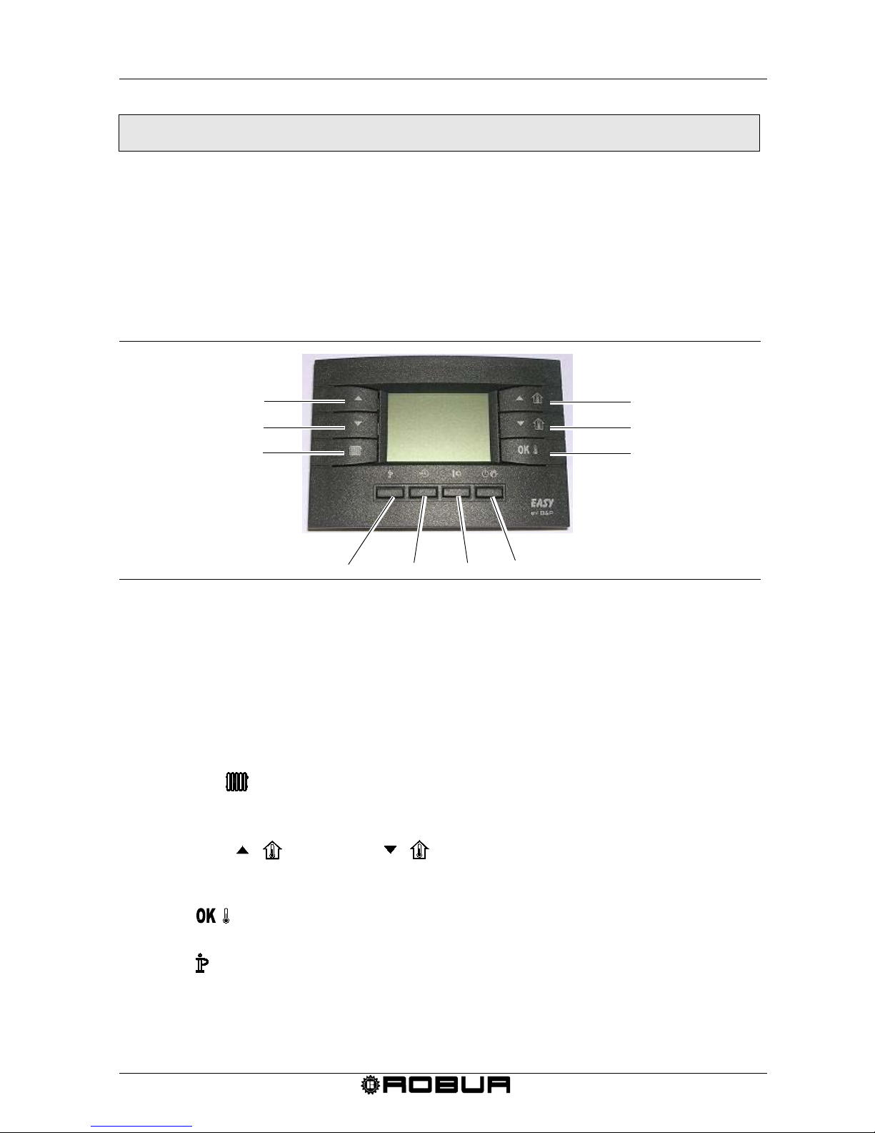
The functioning of the K series heating unit is controlled by a digital chronothermostat that
is supplied as standard with the heater (see Figure 3).
The chronothermostat performs the duel functions of a room thermostat and programming
clock besides diagnosing any operational errors.
All the necessary instructions for the correct use of the chronothermostat are reported
below.
Figure 3 – Digital chronothermostat
2.1 FUNCTIONS OF CHRONOTHERMO STAT
The button s of the chronothermostat have the following functions:
- UPLEV ( ▲)and DOWNLEV ( ▼) buttons: they allow to modify the level of heating
output/air flow from level 0 to level 3 (level 1 minimum heat input, level 2 medium heat
input, level 3 maximum heat input; selecting level 0 during winter operating mode the
heating input would modulate in automatic mode, selecting level 0 during summer
operating mode it would obtain the switch off of the fan(s)).
- Button E/I ( ) permits to select the winter operating mode (on the display it will
appear the radiator icon) or summer operating mode (the burner is off, ONLY the
fan(s) will work).
- Buttons UP ( ) and DOWN ( ): permit to modify the temperature of ambient
set point; the increasing would be a tenth of degree. Maintaining pressed one of the
two buttons it would obtain a quicker and continuous variation.
- Button : permits to visualise the actual ambient temperature, the ambient
temperature desired, confirm the set data
- Button : in order to enter in programming mode to access to menu INFO as specified
here below:
UPLEV
DOWNLEV
E/I
UP
DOWN
OK
IP
TIME
TEMP
FUNCT
Page 13
Condensing Gas Fired Unit Heaters – G Series: Manual of installation, use and maintenance
10 Ed. 09/2018
• Programming mode PROG: press briefly the button , on the display will appear for few
seconds PROG; in order to exit from programming mode press again briefly the butt on
, on the display will appear for few secon ds RUN.
• menu INFO: press for at least 3 seconds the button , on the display will appear for a
few seconds info; to exit from menu info press again briefly the button , on the
display will appear for few seconds RUN.
- Button TIME ( ): it permits to set timing functions (for more information see
paragraph 2.7 – TIMED FUNCTIONS OF THE CHRONOTHERMOSTAT at page 15).
- Button TEMP ( ): it permits to select the temperature of comfort or the reduced one.
- Button FUNCT ( ) to set the automatic, manual or off fu ncti oni ng .
When the functioning off is selected the gas unit heater is in stand-by: it will remain
active ONLY the anti-freezing functioning (in case it would not be disabled in the me nu
info – for more information see paragraph 2.9 – INFORMATION SCREEN OF THE
CHRONOTHERMOSTAT at page 18).
The functions of the buttons here above described would refer to the s tand ar d
functioning. The buttons change their function depending on the window visualised.
2.2 SETTING THE TIME AND DAY ON THE CHRONOTHERMOS TAT
Requirements: The chronothermostat must be connected to the heater’s electrical
board and the heater must be connected to the electrical system.
To set the current time and date, proc e ed as fol lows:
1. Enter into the programming mode by briefly pressing the button: PROGR will
appear on the display for a few seconds and then the time and day of the week will
appear with the DAY icon being shown.
2. With the and buttons the selected value can be changed (which is
blinking). To move from one value to another, press either the or the button.
3. After having set the correct time and date, press the button to exit the
programming mode, RUN will then appear on the display for a few seconds.
2.3 SETTING THE COMFORT, ECONOMY AND ANTI- FREEZING
TEMPERATURES ON THE CHRONOTHERMOSTAT
Requirements: The chronothermostat must be connected to the heater’s electrical
board and the heater must be connected to the electrical system.
1. Enter into the programming mode by briefly pressing the button.
2. Repeatedly press the button to arrive at the temperature that you would like to
set.
Page 14
Condensing Gas Fired Unit Heaters – G Series: Manual of installation, use and maintenance
Ed. 09/2018 11
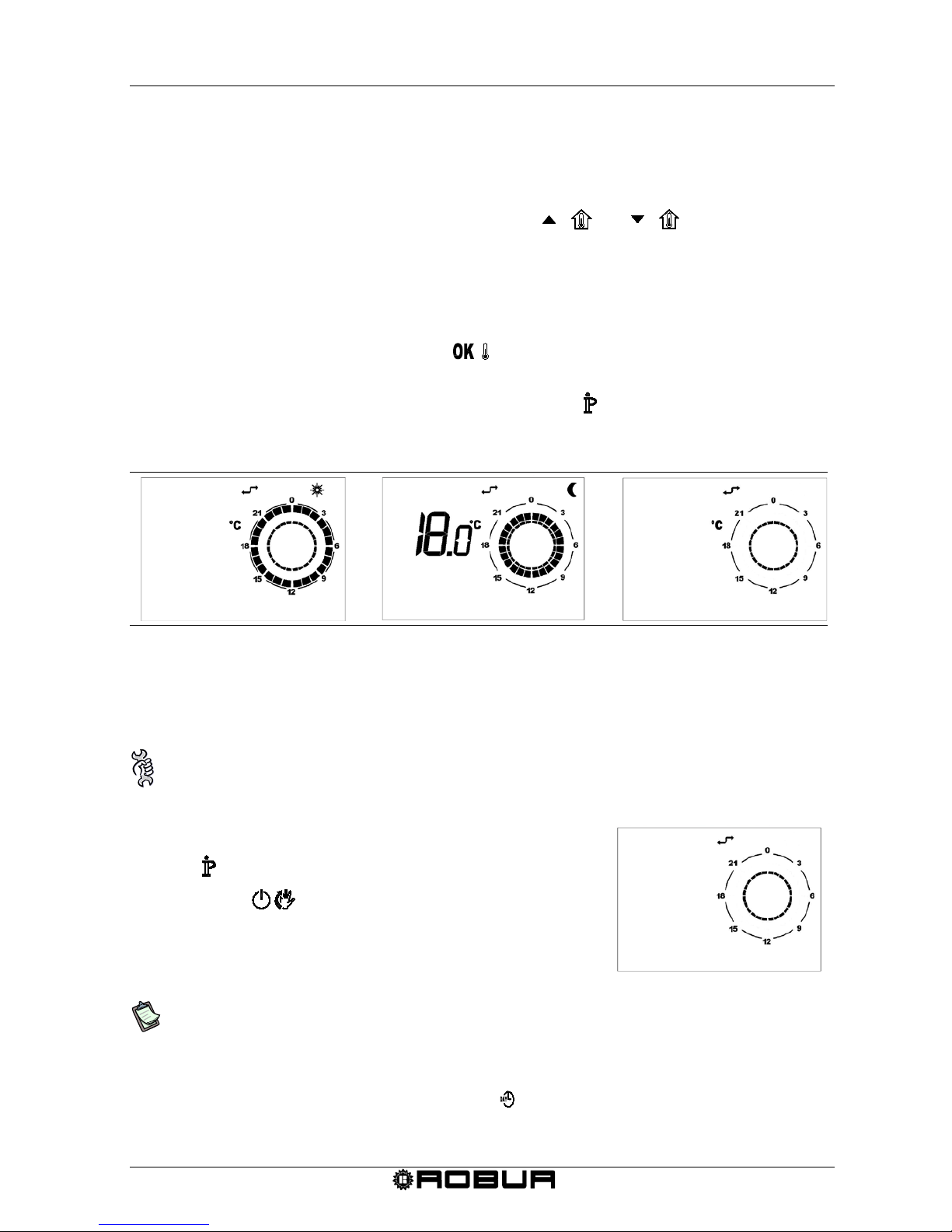
3. In the lower left-hand corner of the display, COMFR will appear for the programming
of the comfort temperatur e, ECONM will appear for the programming of the
economy temperature, and OFFºc will appear for programming of the freeze
protection temperature (see Figure 4).
The desired temperature can be set using the and buttons.
The comfort temperature must be between 5.0 and 30.0°C (with 0.1°C increments);
The economy temperature must be bet ween 5.0 and 25.0°C (with 0.1°C
increments);
The anti-frost temperature must be between 2.0 and 10.0°C (with 0.1°C
increments);
4. To confirm the set value press the button. In this manner you will go to the
successive set.
5. After having set the desired temperature, press the button to exit the
programming mode.
Figure 4 – Comfort, economy and anti-freez ing tem peratures
2.4 PROGRAMMING OF THE DAILY SET POINT ON THE
CHRONOTHERMOSTAT
Requirements: The chronothermostat must be connected to the heater’s electrical
board and the heater must be connected to the electrical system.
1. Enter into the programming mode by briefly pressing
the button.
2. Press the button repeatedly.
3. In the lower left-hand corner of the display, SP n will
appear where n is the number of daily set points (See
figure 6).
Figure 5 – Daily set point.
The daily set point refers to the time at which the operation setting, that is, the
desired temperature level, changes. The set temperature value remains valid until
the next set point.
4. Set the desired day of the week using the button.
5. Select the set point to set using the and buttons.
SP
1
SET
DAY 1
20.
0
comfr
ECONM
5.
0
OFFºC
Page 15
Condensing Gas Fired Unit Heaters – G Series: Manual of installation, use and maintenance
12 Ed. 09/2018
6. Adjust the time using the and buttons (minimum 10 minute intervals).
7. Set the desired temperature level using the : button: in the upper right of the
display, the sun will appear for the Comfort setting, the moon for economy setting,
and no icon for the anti-frost setting.
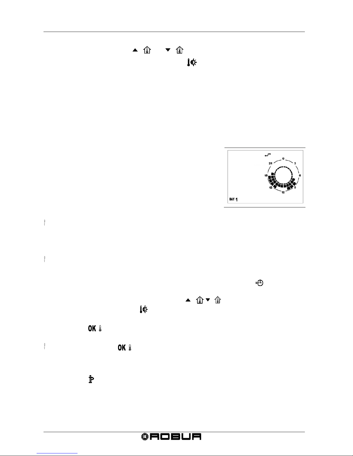
8. The set time and temperature level will be graphically shown on the clock of the
display (see Figure 6).
9. To move to the programming of the next set point, press the ▲or ▼button and set
the time and temperature level as before: up to 8 set points can be set for each daily
profile.
10. In the example of Figure 6 for a Monday, 7 set points were made as specified below:
• Set point 1 at 00:00 anti-frost temperature
• Set point 2 at 7:00 econm temperatur e
• Set point 3 at 8:00 comfr temperature
• Set point 4 at 11:00 econm temperature
• Set point 5 at 14:00 comfr temperature
• Set point 6 at 18:00 econm temperature
• Set point 7 at 19:00 anti-frost temperature
Figure 6 – Daily set point.
When programming the daily set points, it is important to ALWAYS program all 24
hours, as in the example in Figure 6. If times are left unprogrammed, the
chronothermostat will automatically apply the set data from the previous day for that
same time frame (even if it is not shown on the display).
In order to simplify the programming of the daily set points, a preset day profile can
be associated to a specific day (see paragraph 2.5 - SELECTING A PRESET DAILY
PROFILE ON THE CHRONOTHERMOSTAT - on page 13 and then select that
same day in the programming mode of the daily set point (using the button);
proceed in changing the daily profile by scrolling the set points with the and
buttons and changing the time using the buttons and the
temperature level using the button.
11. Once the day profile and the relative temperature set points have been programmed,
press the button to confirm.
Confirming with the button will replace the previously set day profile with the
newly confirmed profile. If confirmation is not provided, all entered settings will be
lost.
12. Press the button to exit the programming mode.
19:00
SET
SP
7
Page 16
Condensing Gas Fired Unit Heaters – G Series: Manual of installation, use and maintenance
Ed. 09/2018 13
HOW TO CHECK DAILY SET POINTS SETTINGS
1. Enter the programming mode by briefly pressing the button.
2. Press the button repeatedly.
3. On the lower left side of the display, SP n will appear where n indicates the number
of the daily set point.
4. Use the button to select the day of the week desired.
5. Use the and buttons to scroll the set points that are set.
6. Press the button to exit.
2.5 SELECTING A PRESET DAILY PROFILE ON THE
CHRONOTHERMOSTAT
Requirements: The chronothermostat must be connected to the heater’s electrical
board and the heater must be connected to the electrical system.
1. Enter into the programming mode by briefly pressing
the button:
2. Repeatedly press the ( ) button:
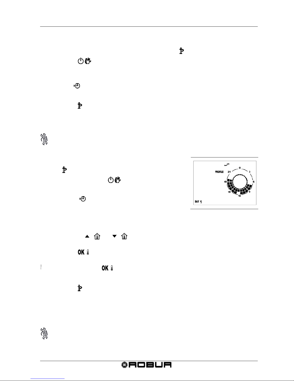
3. Day will appear on the lower left side of the display.
4. Press the button and choose the desired day of the
week.
Figure 7 – Daily profile
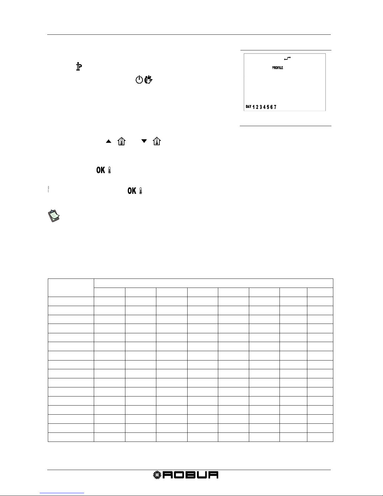
5. In the upper right-hand corner of the display, the word PROFILE and the selected
profile number will appear and be flashing (Figure 7).
6. Pressing the and buttons, one of 16 possible daily profiles can be
selected (see Table 3 at page 14).
7. Press the button to confirm.
Confirming with the button will replace the previously set daily profile with the
newly confirmed profile.
8. Press the button to exit the programming mode.
2.6 SELECTING A PRESET WEEKLY PROFILE ON THE
CHRONOTHERMOSTAT
Requirements: The chronothermostat must be connected to the heater’s electrical
board and the heater must be connected to the electrical system.
0 1
Day 1
Page 17
Condensing Gas Fired Unit Heaters – G Series: Manual of installation, use and maintenance
14 Ed. 09/2018
1. Enter into the programming mode by briefly pressing
the button:
2. Repeatedly press the ( ) button:
3. The word WEEK will appear in the lower left-
hand corner
of the display.
4. On the upper right side of the display, PROFILE will
appear and the number of the selected profile will flash.
Figure 8 – Weekly profile
5. Pressing the and buttons, one of 16 possible weekly profiles can be
selected (see Table 4).
Each weekly profile is a collection of 7 preset daily profiles.
6. Press the button to confirm the selected weekly profile.
Confirming with the button will cancel any previously set weekly profile or daily
profile.
We recommend selecting the weekly profile that is closest to your needs and then,
for the days in which you do not want the daily profile set in the weekly profile, set
the desired preset daily profile as described in the corresponding paragraph, (see
paragraph 2.5 - SELECTING A PRESET DAILY PROFILE ON THE
CHRONOTHERMOSTAT at page 13) or proceed with freely programming the daily
set points (see paragraph 2.4 - PROGRAMMING OF THE DAILY SET POINT ON
THE CHRONOTHERMOSTAT at page 11).
DAILY
PROFILES
TIMETABLE AND TEMPERATURE LEVEL ASSOCIATED WITH THE DAILY SET POINTS
1 2 3 4 5 6 7
8
01 00:00 A 05:30 C 21:30 A --- --- --- --- ---
02
00:00 R 05:30 C 21:30 R --- --- --- --- ---
03
00:00 A
07:00 C
12:00 R
13:00 C
19:30 A
---
---
---
04 00:00 R 07:00 C 12:00 R 13:00 C 19:30 R --- --- ---
05
00:00 R 05:30 C 15:00 R --- --- --- --- ---
06 00:00 A 06:30 C 19:00 A --- --- --- --- ---
07
00:00 A 05:00 R 06:30 C 19:00 R 21:00 A --- --- ---
08
00:00 A
08:00 C
12:00 R
13:00 C
18:00 A
---
---
---
09 00:00 A 04:00 R 07:00 C 18:00 R 21:30 A --- --- ---
10
00:00 A 04:00 R 07:00 C 14:00 R 21:30 A --- --- ---
11 00:00 A 07:00 C 14:30 A --- --- --- --- ---
12
00:00 R 06:00 C 12:00 R 14:00 C 20:00 R --- --- ---
13 00:00 A 05:00 C 12:00 R 13:00 C 21:00 A --- --- ---
14 00:00 C --- --- --- --- --- --- ---
15
00:00 R --- --- --- --- --- --- ---
16 00:00 A --- --- --- --- --- --- ---
Table 3 – Daily profile.
- A: ANTI FREEZING TEMPERATURE; - R: REDUCED TEMPERATURE; - C: COMFORT TEMPE RATURE .
week
0 1
Page 18
Condensing Gas Fired Unit Heaters – G Series: Manual of installation, use and maintenance
Ed. 09/2018 15
WEEKLY
PROFILES
DAILY PROFILES ASSOCIATED TO EACH DAY OF THE WEEK
MONDAY
TUESDAY
WEDNESDAY
THURSDAY
FRIDAY
SATURDAY
SUNDAY
01 01 01 01 01 01 16 16
02
01 01 01 01 01 01 16
03 06 01 01 01 01 16 16
04
06 01 01 01 01 01 16
05
02
02
02
02
02
16
16
06 02 02 02 02 02 02 16
07
06 02 02 02 02 16 16
08 06 02 02 02 02 02 16
09
01 01 01 01 01 01 01
10
14
14
14
14
14
14
14
11 02 02 02 02 02 02 02
12
06 06 06 06 06 06 06
13 07 07 07 07 07 07 07
14
08 08 08 08 08 08 08
15
09 09 09 09 09 09 09
16 10 10 10 10 10 10 10
Table 4 – Weekly profiles
2.7 TIMED FUNCTIONS OF THE CHRONOTHERMOS TAT
There are 3 types of timed functions:
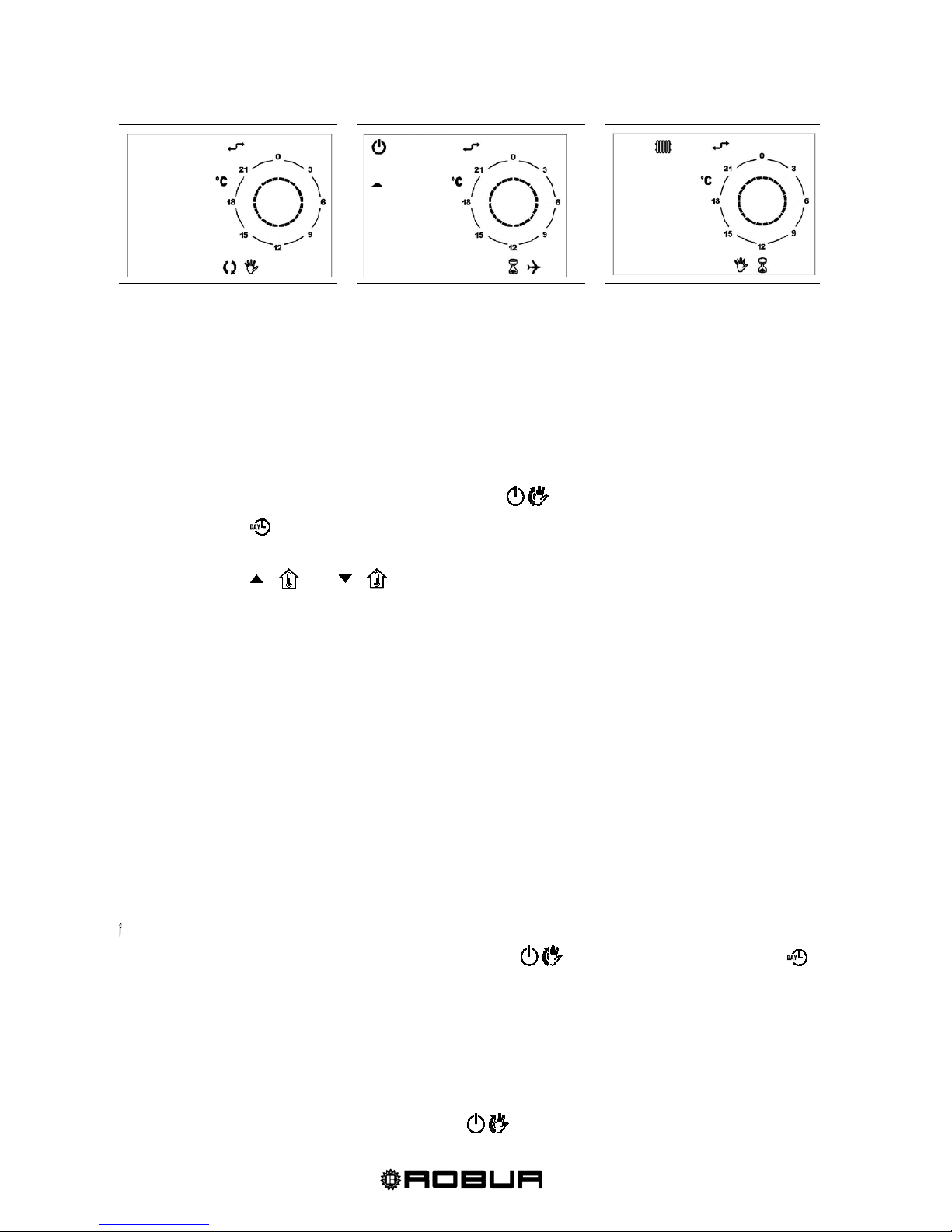
- FORCED AUTOMATIC operation: noted by the presence of both the automatic and
manual icons (see Figure 9).
- TIMED OFF (VACATION PROGRAM) function: noted by the presence of both the
hourglass and airplane icons (see Figure 10).
- TIMED MANUAL (PARTY) operation: noted by the presence of both the hourglass
and manual icons (see Figure 11).
FORCED AUTOMATIC OPERATION
The forced automatic functi o n allows you to set a temperature differ ent fro m the
programmed temperature (for example, the program is set so that the heating unit will
operate from the hours of 8:00 to 12:00 at t he prog r ammed temperature of 18°C but the
day is particularly cold and you would like to heater to operate until a temperature of 20°C
is reached).
To activate the forced automatic function, just press the and buttons and set
the desired temperature (in the example 20ºC). Both the automatic and manual icons will
appear on the display (see Figure 9).
The forced automatic operation will continue until the next programmed set point (in the
example, up to 12:00), and will then return to the automatic mode using the programmed
temperatures.
The FORCED AUTOMATIC function can ONLY be activated while in the
AUTOMATIC mode ( button).
Page 19
Condensing Gas Fired Unit Heaters – G Series: Manual of installation, use and maintenance
16 Ed. 09/2018
Fig
ure 9 – Forced automatic mode
Fig
ure 10 – Timed shut down mode Figure 11 – Timed manual mode.
TIMED SHUT DOWN MODE (VACATION PROGRAM)
This turns off the unit for a certain period of time; in this period of time, any automatic
programs that were set are disenabled whereas the antifreeze function remains active; ((if
it has not been deactivated fro m the INFO menu – see Table 5 at page 18).
The timed shutdown function is particularly useful when on vacation.
To activate the timed shut dow n func ti on, pr o ceed as fol l ows:
1. Select the AUTOMATIC function using the button.
2. Press the button (the hourglass and airplane icons will appear and the word
OFF will continually cross the display).
3. Using the and buttons, set the time the unit is to be shut down. The
time can be expressed in:
• minutes from 10 to 90 (reading MM:nn) (can be increased or decreased in 10
minute increments)
• hours from 2 to 47 (reading HH:nn) (can be increased or decreased in 1 hour
increments)
• days from 2 to 45 (reading DD:nn) (can be increased or decreased in increments
of 1 day)
The passage from minutes to hours and from hours to days is done through
progressive increments of the parameter shown on the video.
4. During the entire period, the time remaining for the timed function will be displayed
(see Figure 10 at page 16).
5. After the timed shut down period has finished, the chronothermostat will begin the
automatic program.
The timed function can be interrupted at any moment by selecting the SHUT DOWN,
AUTOMATIC or MANUAL function (using the button) or by repressing the
button.
TIMED MANUAL OPERATION (PARTY)
Lets you set a desired temperature for a certain period of time, after which it switches to
AUTOMATIC operatio n.
To activate the timed manual mode, proce ed as follows:
1. Select the MANUAL function using the button.
DAY 1
20.
0
AMB
SET
16.
0
Mm
21
0
Hh 2
SET
Page 20
Condensing Gas Fired Unit Heaters – G Series: Manual of installation, use and maintenance
Ed. 09/2018 17
2. With the and buttons, set the desired temperature.
3. Press the button (the hourglass and hand icons will appear on the display).
4. Using the and buttons, set the duration for manual oper a t ion. The time
can be expressed in:
• minutes from 10 to 90 (reading MM:nn) (can be increased or decreased in 10
minute increments)
• hours from 2 to 47 (reading HH:nn) (can be increased or decreased in 1 hour
increments)
• days from 2 to 45 (reading DD:nn) (can be increased or decreased in increments
of 1 day)
The passage from minutes to hours and from hours to days is done through progressive
increments of the parameter shown on the video.
5. During the entire period, the time remaining for the timed function will be displayed
(see Figure 11 at page 16).
6. After the period of timed manual operation has finished, the chronothermostat will
begin the automatic program.
The timed function can be interrupted at any moment by selecting the SHUT DOWN,
AUTOMATIC or MANUAL function (using the button) or by repressing the
button.
2.8 KEYBOARD BLOCK
The chronothermostat can be protected from tampering or involuntary settings by
activating the keyboard block function (KEY ) as follows:
1. Enter the INFO menu by pressing the button for more than 3 seconds. INFO will
appear on the display
2. Press the button until the string KEY appears.
3. Activate the keyboard block by setting value 1 using the and buttons.
4. Press the button to exit from the INFO menu
5. 10 minutes after the last time any key is pressed, the keyboard block function will be
activated.
The activation of the keyboard block is shown on the display by the “asterisk” symbol
that appears next to the time.
6. To reactivate keyboard use, press the buttons in the following sequence , ,
and .
7. To deactivate the keyboard block function, repeat the instructions indicated in
sections 1, 2 and 3, setting the value to 0.
Page 21
Condensing Gas Fired Unit Heaters – G Series: Manual of installation, use and maintenance
18 Ed. 09/2018
2.9 INFORMATION SCREEN OF THE CHRONOTHERMOSTAT
The information menu (INFO) contains 8 parameters that provide information about the
unit’s operating mode; some of these parameters can be changed and are used to
personalise the operating mode of the installed unit.
1. Enter the INFORMATION mode by pressing and holding the button for at least 3
seconds: the word INFO will appear on the display.
2. By pressing the button the information windows seen in Table 5 can be viewed.
STRING DESCRIPTION
CHANGEABLE
PARAMETER
NΓ C1 Visualization of the output air temperature. NO
NΓ C2
Visualization of flue temperature
NO
SP %
This value, which is calculated directly by the circuit board, indicates the
instantaneous percentage of the modulation range of the power
1
effectively supplied by the unit.
NO
SP MX %
This parameter changes the unit’s modulation
1
range to change the
maximum limit (maximum power supplied by the unit).
By setting a value equal to 50%, the UNIT will run from the value of 0 up
to 50% of the modulation range contained between the foreseen
maximum (100%) and minimum (0%).
As default, this parameter is set at 100%.
It can be particularly useful to set a percentage lower than 100 when the
system is too large for its intended use.
YES
using the UP and DOWN
buttons
can be changed from 100%
to 0%
RPM Displays the instantaneous revolutions of the blower. NO
KEY Enables or disenables the chronothermostat’s keyboard block
YES
using the UP and DOWN
buttons
0 = block deactivated
1 = block activated
BUILD
Building dimension parameter. Can be set from 1 to 10: a value of 1 is
recommended if the area to heat is of reduced dimensions; value 10 if
the area to be heated is large.
Default parameter is 5.
YES
using the UP and DOWN
buttons
can be modified from 1 to
10
NO FRX
Enables or disenables anti-freezing function
2
.
To activate it, it is necessary to set value 1 by using the button UP and
press OK to confirm.
To disenables it is necessary to set value 0 by using the button DOWN
and press OK to confirm.
SI
attraverso i tasti UP e
DOWN
1 = antigelo attivo
0 = antigelo disattivo
Table 5 – Information screen.
1 TO BETTER UNDERSTAND THE THERMAL POWER OR MODULATION PERCENTAGE , RE FE R TO THE SPECI FIC NOTE AT PAGE
19.
2 THE ANTIFREEZE FUNCTION IS THE FUNCTION THAT ACTIVATES THE UNIT IF THE TEMPERA TURE OF THE ROOM IN WHICH
THE UNIT IS INSTALLED D ECREASES BELOW T H E SET ANTIFREE ZE TEMPERATURE (FOR MORE DETAILS SEE PARAGRAPH 2.3
SETTING THE COMFORT, ECONOMY AND ANTI- FREEZING TEMPERATURES ON THE CHRONOTHERMOSTAT AT PAGE10).IF THE
VALUE SET FOR THE ANTI-FREEZING TEMPERATUREIS HIGHER THAN THE SET POINT TEMPERATURE,THIS SHALL CONTROL
THE TURNING ON OF THE UNIT.
Page 22
Condensing Gas Fired Unit Heaters – G Series: Manual of installation, use and maintenance
Ed. 09/2018 19
Percentage of heating output means the percentage of the modulation field
included between th e nominal and the minimum heating output (see Table 2).
For example, setting the parameter "SP MX %" (limit maximum of the heating output)
the value "50", the range of modulation of the heater will be from "0%" to "50%".
To know at which heating output the heater will work it is necessary to do the
following operation (referred to the example here above and thinking about the
heater would be a G100):
Modulation field maximum [(100-0)%] = (90,2 kW – 33,5 kW) = 56,70 kW
Modulation heating output = (56,70 kW x 50 %) = 28,35 kW
Functioning heating output = (33,5 kW + 28,35 kW) = 61,85 kW.
2.10 SELECTION MENU WINDOW
The selection menu contains 6 parameters that are used to personalise the operating
mode of the installed unit.
1. Access the SELECTION MENU by pressing the button for 3 seconds and then,
after accessing the INFO menu, by pressing the and buttons at the same
time.
2. Scroll the menu parameters using the and buttons.
3. Once the parameter to change has been selected, make the change using the UP
( ) and DOWN ( ) buttons. Once changed, the parameter value will start to
flash. The parameter has been accepted when the flashing stops.
If a value not permitted for the selected parameter has been set, the default value
shown in Table 6 will be restored.
4. Press to return to the INFO menu.
5. Press to exit the info menu and return to the main screen.
Page 23
Condensing Gas Fired Unit Heaters – G Series: Manual of installation, use and maintenance
20 Ed. 09/2018
PARAMETER DESCRIPTION FUNCTIONALITY DEFAULT VALUE
PM 01 Operating mode
01 – standard
02 – function not applicable
03 – ventilation priority (only without
a chronothermostat)
Default : 01
PM 02
Ventilation speed in ventilation
priority mode (only without a
chronothermostat)
1 – low speed
2 – medium-low speed
3 – medium-high speed
4 – high speed
Default : 4
PM 03
Lower modulation depth limit in
standard mode.
Indicates the lower modulation
value of the unit’s thermal
power (0% corresponds to the
minimum supplied power): ex :
by setting 10%, the unit will
adjust from 100% (maximum
supplier power) to 10 % of the
modulation range
1
From 0 to 100 % Default : 0%
PM 04
Upper modulation depth limit in
the increased air flow rate
mode.
PARAMETER NOT
APPLI
CABLE
From 0 to 100 % Default : 76%
PM 05
Upper modulation depth in
standard mode.
It indicates the upper
m
odulation value of the unit’s
thermal power (100%
corresponds to the maximum
supplied power) .
From 0 to 100 % Default : 100%
PM 06 Chronothermostat installed
1: chronothermostat installed
0: chronothermostat not installed
Default : 1
Table 6 – Operating parameters.
1 TO BETTER UNDERSTAND THE THERMAL POWER OR MODULATION PERCENTAGE REFERRS TO THE SPECIFIC NOTE ABOVE
AT PAGE 19, AT THE BOTTOM OF PARAGRAPH 2.9).
2.11 MALFUNCTION WARNINGS
Any malfunctions that may be determined during normal operation of the heater are
identified with the appropriate “error code” on the chronothermostat display.
The table below shows any anomalies visualized on the chronothermostat display, the
failure that occur and the operation to be carried out.
Page 24
Condensing Gas Fired Unit Heaters – G Series: Manual of installation, use and maintenance
Ed. 09/2018 21
ERROR
CODE
DESCRIPTION RESONS INTERVENTION
01 E
(1)
Unit locks out during the first
ignition phase
• The ignition electrode is broken
or badly positioned
• Modify the position or
replace the ignition
electrode
• The flame sensor is broken or
incorrectly positioned or touches
the unit ground.
• Modify the position or
replace the flame sensor
• Failure of dialog board or failure
of its electric connection
• replace the dialog board
• Failure in the gas valve or in its
electrical connections
• replace the gas valve
•
Bad grounding
•
Improve grounding
• Air inside the gas pipes • Remove the air from the
gas supply
After having identified and
resolved the cause of the error,
press the OK button on the
chronothermostat
02 E
(1)
The temperature limit
thermostat stops the burner.
The heat exchanger have
overheated
• Accumulation of dirt in the air
inlet
• Obstruction of ventilation and
supply grill
• Failure in the axial fan
• Electricity black-out during
operation
After having identified and
resolved the cause of the error
reset the limit thermostat
pressing the button OK of the
chronothermostat in order to
reset the error
Flame Error
• Recirculation of flue gas into the
combustion air pipe
• Adjust the position of the
exhaust / combustion air
pipes or replace them if not
suitable for use.
• Defective flame sensor
• Replace flame sensor
• Defective main electronic board • Replace mai n electronic
board
03 E Temperature probe
• The probe that measures the
temperature of the output air is
broken.
The error message turns off
automatically once the anomaly
that caused it has been
eliminated.
06 E
Cable flue exhaust probe cut off
on the board
• False contact on flue exhaust
probe
Replace the contact
07 E
08 E
09 E
Problems on the blower
• Electrical connections faulty
• Failure in the blower motor
• Lack of performance
The error message turns off
automatically once the anomaly
that caused it has been
eliminated.
10 E Problems on flue exhaust probe
• Exhaust flue temperature probe
failed
Replace the probe.
11 E
Lock out caused by minimum
temperature of the flue exhaust
• Combustion flue temperature too
low
Verify that combustion air or
flue pipes are not obstructed or
too long.
Verify that the pipe of
condensate drainage or the
condensing siphon are not
obstructed or with a wrong
diameter.
Verify that flue exhaust probe is
correctly positioned in the flue
collector.
Table 7 – Error codes
(1) WARNING: after four resets 01E and / or 02 E within 1 hour, the error can not be reset manually. In order to reset the error, you
must wait one hour or do a power reset (cut OFF the electrical supply and than switch it ON).
Page 25
Condensing Gas Fired Unit Heaters – G Series: Manual of installation, use and maintenance
22 Ed. 09/2018
The table below shows the failures that are NOT show on display of chronothermostat.
ERROR CODE DESCRIPTION REASONS INTERVENTION
NO error code
The burner goes out and does
not re-ignite even if room
temperature requires it
• Position of
chronothermostat could be
influenced by external heat
sources.
• Check the position of the
chronothermostat
• Check the
chronothermostat setting
• New setting
NO error code
The chronothermostat is ON
and the heater doesn’t work
•
No electrical supply
•
Check electrical supply
• Failure of remote unit
interface
• Replace the remote unit
interface
• Contact on main control
circuit is open
• Close the contact
Table 8 – Failures that are NOT show on display of chronothermostat.
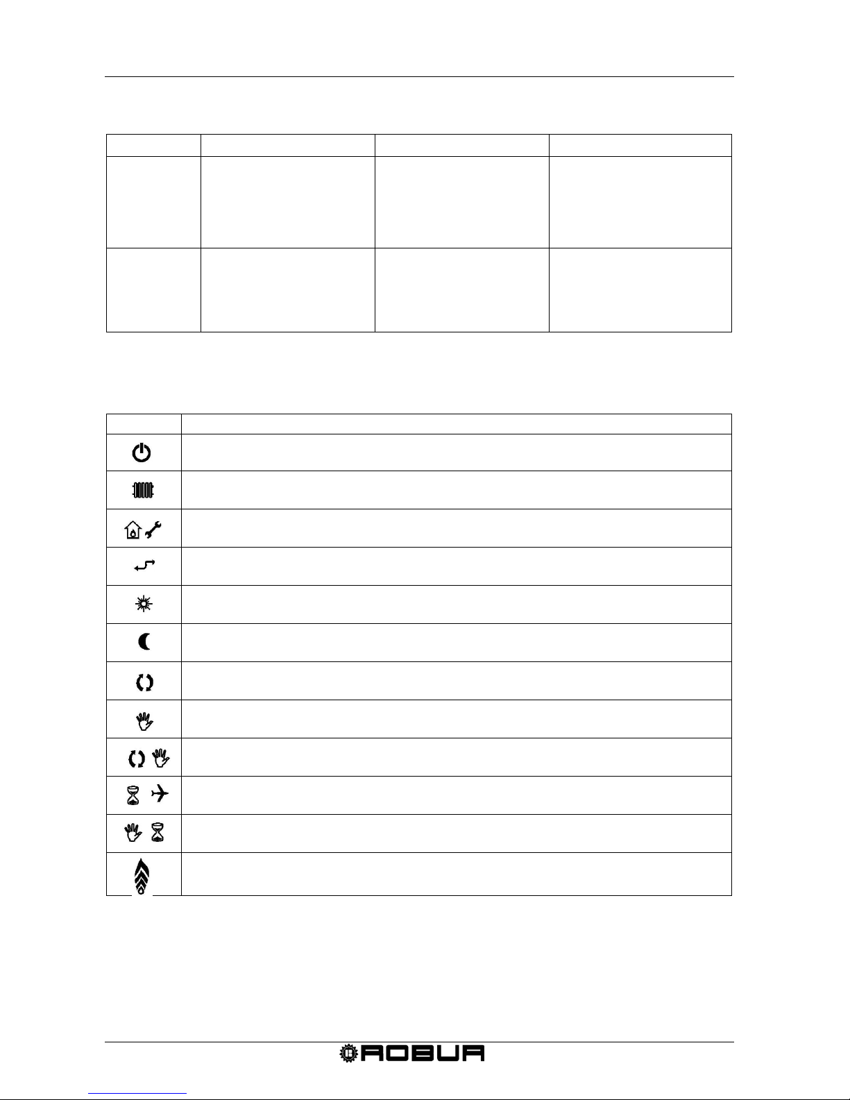
2.12 TABLE OF ICON MEANINGS ON CHRONOTHERMOSTAT DISPLAY
ICON MEANING
The heater is in stand-by mode.
Winter operation enabled.
Error or request for maintenance (see TABLE 7).
Communication between chronothermostat and heater active.
Comfort temperature in use.
Economy temperature in use.
Automatic operation in use.
Manual operation in use.
Forced automatic operation in use.
Timed shut down function in use.
Timed manual operation.
Flame/power level used.
Table 9 – Icon meanings on chronothermost at disp lay .
Page 26

Condensing Gas Fired Unit Heaters – G Series: Manual of installation, use and maintenance
Ed. 09/2018 23
2.13 HOW TO USE THE UNIT HEATER
The Gas Fired Unit Heater has the following use options
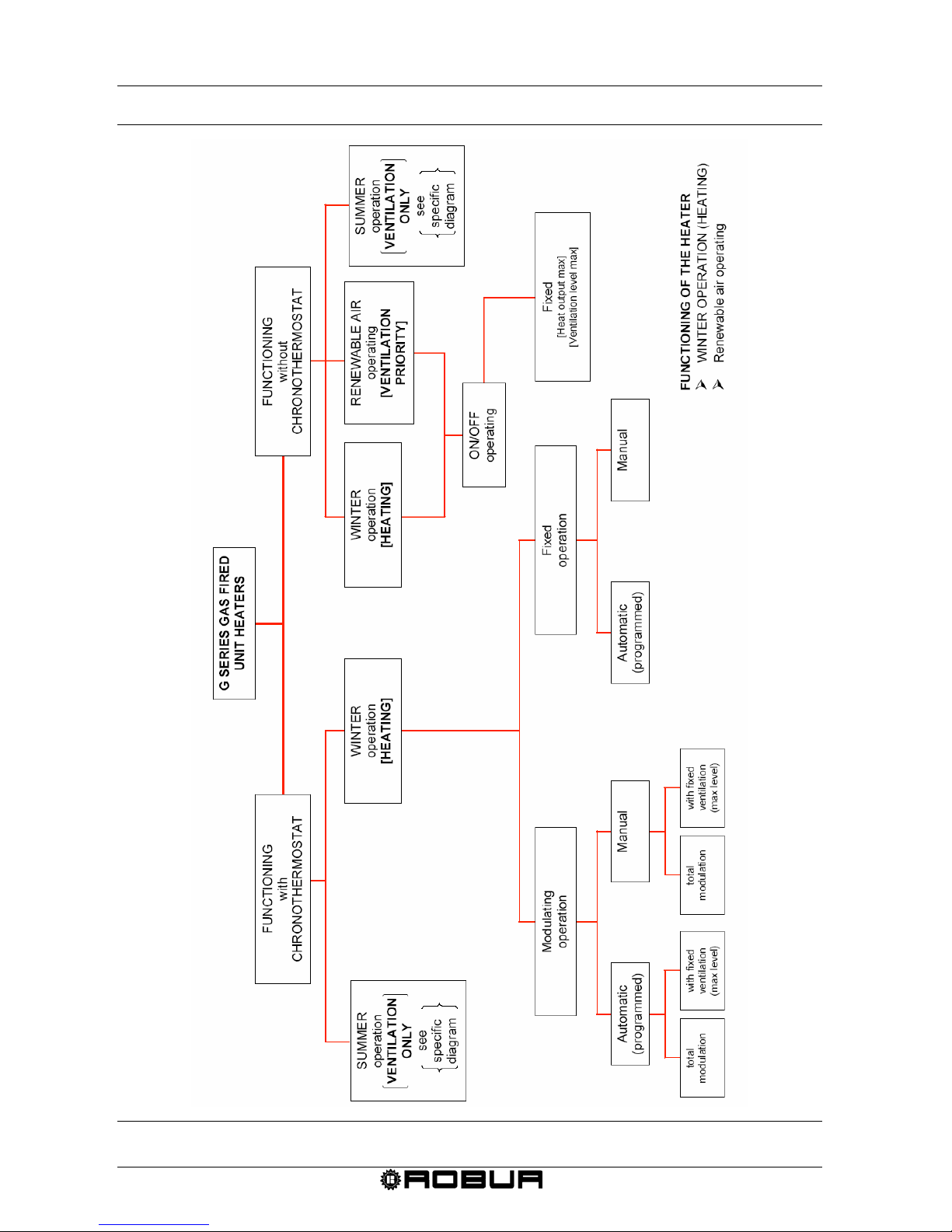
(please refer to the diagrams of Figure 12 and Figure 13, from page 24):
FUNCTIONING WITH CHRONOTHERMOSTAT
(ref. to Paragraph 2.14, page 25)
• Winter operating (Heating)
- with only chronothermostat, it means with chronothermostat and external devices.
• Summer operating (Ventilation only)
- with only chronothermostat, it means with chronothermostat and external devices.
FUNCTIONING WITHOUT CHRONOTHERMOSTAT
(ref. to the Paragraph 2.15, page 30)
• Winter operating (Heating)
• Summer operating (Ventilation only)
• Renewable air functioning (with priority of ventilati on)
The unit is delivered from the factory with sta ndar d m ode functioning, equipped with
chronothermostat.
In order to set a different functioning mode (for example renewable air) please refer
to paragraph 2.10 SELECTION MENU WINDOW at page 19.
Page 27
Condensing Gas Fired Unit Heaters – G Series: Manual of installation, use and maintenance
24 Ed. 09/2018
Figure 12 – Winter operation and renewable air functioning.
Page 28
Condensing Gas Fired Unit Heaters – G Series: Manual of installation, use and maintenance
Ed. 09/2018 25
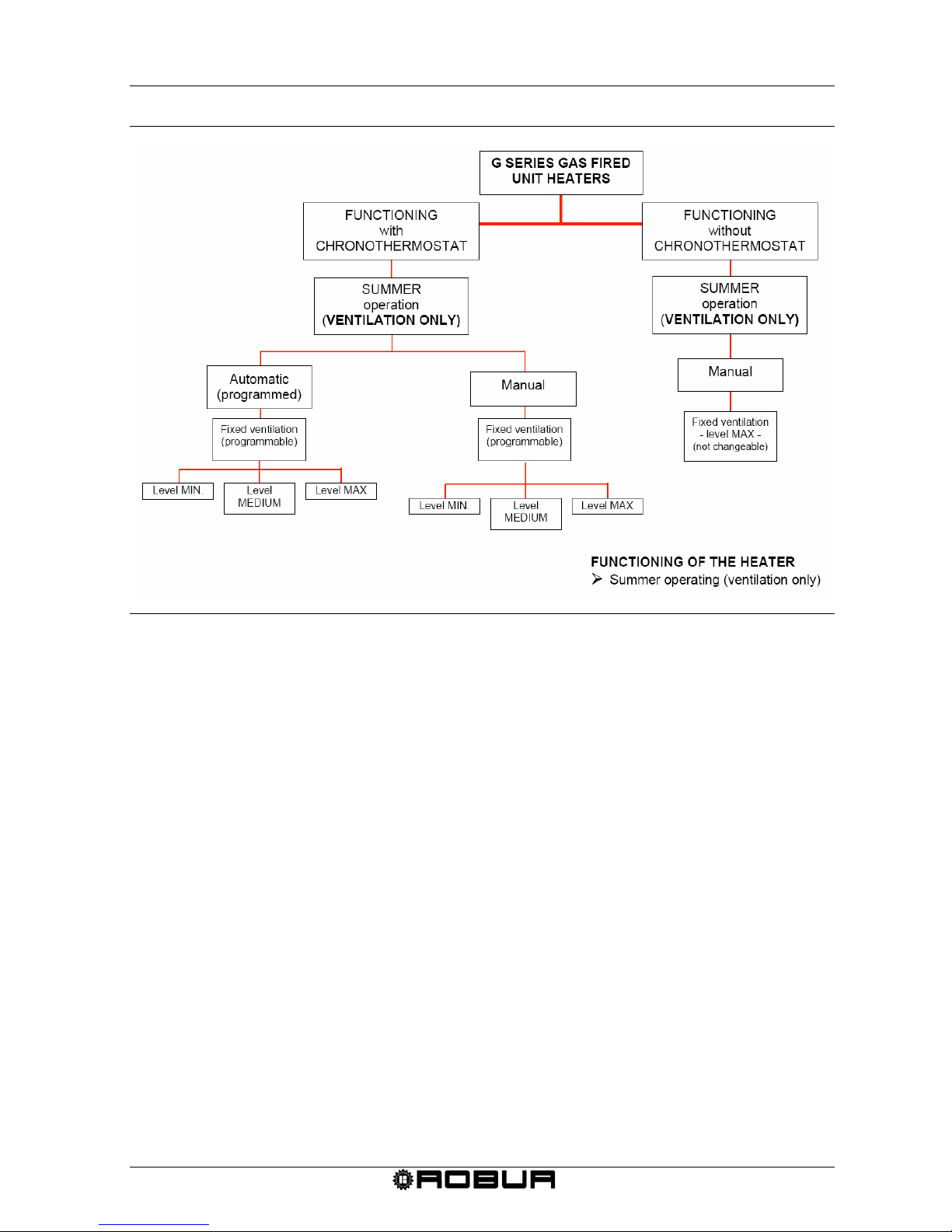
Figure 13 – Summer operation.
2.14 HOW TO USE THE UNIT WITH THE CHRONOTHERMOSTAT
Options of use with the chronothermostat are:
winter operating (heating) and summer operating (ventilation).
WINTER OPERATING (HEATING)
The functioning in heating mode could be modulating or fix (see Figure 12):
A) Automatic modulating functioning
functioning with modulation of the heating output of the unit, controlled automatically
by the chronothermostat following the hourly program set
Total modulation (with modulating ventilation);
With fix ventilation (with constant ventilation at the maxi mu m speed ).
B) Manual modulating functioning
functioning with modulation of the heat output of the unit, controlled manually by the
end user
Total modulation (with modulating ventilation);
With fix ventilation (with constant ventilation at the maximum speed).
C) Automatic fix functioning
functioning with fix heat output controlled automatically by the chronothermostat
following the hourly program set.
Page 29
Condensing Gas Fired Unit Heaters – G Series: Manual of installation, use and maintenance
26 Ed. 09/2018
D) Manual fix functioning
functioning with fix heat output of the unit controlled manually by the end user.
A Automatic modulating functioning standard operation
Total mod ul ati o n (with modulating ventilation)
Requirements: The heater must be connected to the electrical and gas networks.
1. Press the button on the chronothermostat (see Figure 3 at page 9) the winter
operation is confirmed by the appearance of the radiator symbol in the upper left
corner of the display.
2. Program the date, time, temperatures, as well as the weekly and daily profiles on the
chronothermostat as described in the relative paragraphs.
3. Using the button on the chronothermostat (see Figure 3 at page 9) select the
function type: automatic ( ) (in this mode, the unit’s operation is regulated by the
end user defined profiles) .
4. By setting the flow rate level to 0 (▲and ▼ buttons), the thermal power and the air
flow rate are adjusted continuously based on an internal algorithm and on the
temperature difference between the room set point (req ues t ed t e mp er atur e) and the
detected temperature.
If ignition is done after a long period of inactivity, or at the time of the initial ignition of
the unit, the operation may need to be performed numerous times due to air in the
piping.
With fix ventilation (with constant ventilation at the maximum speed)
Requirements: The heater must be connected to the electrical and gas networks.
1. Press the button on the chronothermostat (see Figure 3 at page 9) the winter
operation is confirmed by the appearance of the radiator symbol in the upper left
corner of the display.
2. Program the date, time, temperatures, as well as the weekly and daily profiles on
the chronothermostat as described in the relative paragraphs.
3. Using the button on the chronothermostat (see Figure 3 at page 9) selec t the
function type: automatic ( ) (in this mode, the unit’s operation is regulated by
the end user defined profiles) .
4. By setting flow rate at value 4 (▲and ▼ buttons), the air flow will remain
constant at the maximum speed and the heat output will module continuously
based on an internal algorithm and on the temperature difference between the
room set point (requested temperature) and the detected temperature.
Page 30
Condensing Gas Fired Unit Heaters – G Series: Manual of installation, use and maintenance
Ed. 09/2018 27
If ignition is done after a long period of inactivity, or at the time of the initial ignition of
the unit, the operation may need to be performed numerous times due to air in the
piping.
B Automatic modulating functioning standard operation
Total modulation (with modulating ventilation)
Requirements: The heater must be connected to the electrical and gas networks.
1. Press the button on the chronothermostat (see Figure 3 at page 9) the winter
operation is confirmed by the appearance of the radiator symbol in the upper left
corner of the display.
2. Using the button on the chronothermostat (see Figure 3 at page 9) select the
function type: manual (), (in this mode, the unit’s operation is controlled manually
by the end user).
3. Use the UP ( ) and DOWN ( ) buttons to select the desired room
temperature. If you want to use the set temperature, Economy or Comfort, (see
paragraph SETTING THE COMFORT, ECONOMY AND ANTI- FREEZING
TEMPERATURES ON THE CHRONOTHERMOSTAT at page 10), use the
button to select the desired setting.
4. By setting flow rate level to 0 (▲and ▼ buttons), the thermal power and the air
flow rate are adjusted continuously based on an internal algorithm and on the
temperature difference between the room set point (requested temperature) and the
detected temperature.
If ignition is done after a long period of inactivity, or at the time of the initial ignition of
the unit, the operation may need to be performed numerous times due to air in the
piping.
With fix ventilation (with constant ventilation at the maximum speed)
Requirements: The heater must be connected to the electrical and gas networks.
1. Press the button on the chronothermostat (see Figure 3 at page 9) the winter
operation is confirmed by the appearance of the radiator symbol in the upper left
corner of the display.
2. Using the button on the chronothermostat (see Figure 3 at page 9) select the
function type: manual (), (in this mode, the unit’s operation is controlled manually
by the end user).
3. Use the UP ( ) and DOWN ( ) buttons to select the desired room
temperature. If you want to use the set temperature, Economy or Comfort, (see
Page 31
Condensing Gas Fired Unit Heaters – G Series: Manual of installation, use and maintenance
28 Ed. 09/2018
paragraph SETTING THE COMFORT, ECONOMY AND ANTI- FREEZING
TEMPERATURES ON THE CHRONOTHERMOSTAT at page 10), use the
button to select the desired setting.
4. By setting flow rate at value 4 (▲and ▼ buttons), the air flow will remain constan t
at the maximum speed and the heat output will module continuously based on
an internal algorithm and on the temperature difference between the room set point
(requested temperature) and the detected temperature.
If ignition is done after a long period of inactivity, or at the time of the initial ignition of
the unit, the operation may need to be performed numerous times due to air in the
piping.
C Automatic fix functioning standard operation
Requirements: The heater must be connected to the electrical and gas networks.
1. Press the button on the chronothermostat (see Figure 3 at page 9) the winter
operation is confirmed by the appearance of the radiator symbol in the upper left
corner of the display.
2. Program the date, time, temperatures, as well as the weekly and daily profiles on the
chronothermostat as described in the relative paragraphs.
3. Using the button on the chronothermostat (see Figure 3 at page9) select the
function type: automatic ( ) (in this mode, the unit’s operation is regulated by the
end user defined profiles) .
4. By setting the air flow level to 1, 2 or 3 ( ▲and ▼ buttons) the unit’s operation will be
fixed at the power/flow rate level that is set (1 = low, 2=medium, 3= maximum). The
unit will run without modulation until it reaches the requested temperature.
If ignition is done after a long period of inactivity, or at the time of the initial ignition of
the unit, the operation may need to be performed numerous times due to air in the
piping.
D Manual fixed standard operation
Requirements: The heater must be connected to the electrical and gas networks.
1. Press the button on the chronothermostat (see Figure 3 at page9) the winter
operation is confirmed by the appearance of the radiator symbol in the upper left
corner of the display.
2. Using the button on the chronothermostat (see Figure 3 at page 9) select the
function type: manual ()(in this mode, the unit’s operation is controlled manually
by the end user).
3. Use the UP ( ) and DOWN ( ) buttons to select the desired room
temperature. If you want to use the set temperature, Economy or Comfort, (see
Page 32
Condensing Gas Fired Unit Heaters – G Series: Manual of installation, use and maintenance
Ed. 09/2018 29
paragraph 2.3 - SETTING THE COMFORT, ECONOMY AND ANTI- FREEZING
TEMPERATURES ON THE CHRONOTHERMOSTAT at page 10), use the
button to select the desired setting.
4. By setting the air flow level to 1, 2 or 3 ( ▲and ▼ buttons) the unit’s operation will be
fixed at the power/flow rate level that is set (1 = low, 2=medium, 3= maximum). The
unit will run without modulation until it reaches the requested temperature (room
thermostat on).
If ignition is done after a long period of inactivity, or at the time of the initial ignition of
the unit, the operation may need to be performed numerous times due to air in the
piping.
SHUTDOWN
Requirements: The heater must be connected to the electrical and gas networks.
1. To turn off the heater, select the of f mode usi ng the button: the icon ( ).
In this mode, the unit is in stand-by: only the antifreeze function remains active
unless deactivated fro m the INFO menu (see “NO FRX” of Table 5).
To avoid damage to the appliance, never turn it off by removing electrical power;
doing this will cause the immediate arrest of the fans and the intervention of the
temperature limit ther most at , w hic h must be r es et man uall y.
SUMMER OPERATION (VENTILATION ONLY)
Functioning with ventilation only coul d be wi th manual ventilation or with automatic
ventilation (see Figure 13).
Requirements: The heater must be connected to the electrical and gas networks.
1. Close the gas valve and check that the appliance has electrical power.
2. Press the button on the chronothermostat. The icon representing the radiator
symbol will disappear.
3. Use the ▲ and ▼ buttons to select the ventilation level (level 1 minimum ventilation,
level 2 medium ventilation, level 3 maximum ventilation). By setting level 0, there is
no ventilation (the fans turn off).
4. During SUMMER operation, the burner is off and only the fan(s) operates to circulate
the air.
During summer operation, the following ventilation modes can also be selected using the
FUNCT ( ) button (see also Figure 13):
- manual ventilation (MAN): continuous ventilation without time limits at the selected
ventilation level;
- automatic ventilation (AUTO ) the programmed time intervals are used to start the
ventilation at the selected level (COMFR), or to turn off the ventilation (ECONM).
Page 33
Condensing Gas Fired Unit Heaters – G Series: Manual of installation, use and maintenance
30 Ed. 09/2018
2.15 HOW TO USE THE UNIT WITHOUT A CHRONOTHERM O STAT
Options of use, without the chronothermostat, are:
winter operating, summer operating and renewable air operating.
WINTER OPERATING (HEATING) AND
SUMMER OPERATING (VENTILATION ONLY)
1. Access the SELECTION MENU by pressing the button for 3 seconds and then,
after accessing the INFO menu, by pressing the buttons at the same time.
2. Set the PM06 parameter “Chromothermostat presence” to 0 (without a
chronothermostat) (see Table 6).
3. Press to return to the INFO menu.
4. Press to exit the INFO menu and return to the main screen.
5. Disconnect the remote control and remove the dialogue board located in the control
circuit in position x13.
6. To make the unit run in winter simply close the contact marked with the “radiator”
symbol located on the LC23 board. In this way, the unit will not run in the modulating
mode but in an ON-OFF mode with fixed thermal power and ventilation (maximum
settings).
7. To make the unit run in summer (only fans) close the contact marked with the “fan”
symbol located on the LC23 board. In this way, the fan will run at maximum
ventilation.
8. Concerning the remote signalling of the anomalies, refer to paragraph 4.4 REMOTE
SIGNALLING OF THE ANOMALIES at page 48.
For more information regarding unit operation and use in this mode, directly contact
Robur’s Pre-Sales service on +39 035/888.111
TOTAL FRESH AIR (ventilation priorità)
Total fresh air operating is possible ONLY without chronothermostat.
This option allows an on/off functioning with continuous ventilation and with burner on only
when heating is needed (ambient thermostat contact closed).
Air flow and heat output are fixed (maximum values).
This function is particularly useful if a CONSTANT RENEWABLE AIR OF THE AMBIENT
is needed.
In order to set this functioning mode follow the instructions here below.
1. Access the SELECTION MENU by pressing the button for 3 seconds and then,
after accessing the INFO menu, by pressing the buttons at the same time.
2. Set the PM01 parameter “Functioning mode” to 03 (priority ventilation) (see Table
6).
Page 34
Condensing Gas Fired Unit Heaters – G Series: Manual of installation, use and maintenance
Ed. 09/2018 31
3. Set the PM06 parameter “Chromo thermostat presence” to 0 (without a
chronothermostat) (see Table 6).
4. Press to return to the INFO menu.
5. Press to exit the INFO menu and return to the main screen.
6. Disconnect the remote control and remove the dialogue board located in the control
circuit in position x13.
The settings here above permit to use the heater with two options: "ventilation only"
mode (for renewable air) so "ventilation and heating contemporary" (to renew the air
and to heat the ambient). This option, then, does not allow the mode "heating
only", granting the priority to the ventilation.
7. To activate the mode "ventilation only" (functioning of the fans only, for the
renewable air) it is necessary to close only the contact with the symbol “fan” on the
LC23 board.
Option, for example, for summertime.
8. To activate the mode "ventilation with heating" (contemporary functioning of fans and
burner, for renewable air and heating mode) it is necessary to close, not only the
contact with “fan” symbol but also the contact with the symbol “radiator”, both
positioned on the LC23 board.
To disable the heating mode (turn off of the bur ner only) re- open the contact with
the symbol “radiator”.
Option, for example, for wintertime.
9. To remote the signalling anomalies refer to paragraph 4.4 REMOTE SIGNALLING
OF THE ANOMALIES at page 48.
For more information regarding unit operation and use in this mode, directly contact
Robur’s Pre-Sales service on +39 035/888.111
2.16 SETTING FIELD
By the use of the chronothermostat it is possible to set the heat input of the unit, fixing a
value (in percentage) different than the nominal one.
This option modifies the maximum heat output of the unit and it can be selected anytime
you want the heater has a heat input lower than the nominal one.
The setting of the heat input can be done only by an Authorised and Qualified
Technical Service.
In case of Service, the parameter to be modified is "PM 05": see Table 6, page 20.
For the eventual setting, please follow the instructions in the Paragraph 2.10
of Page 19.
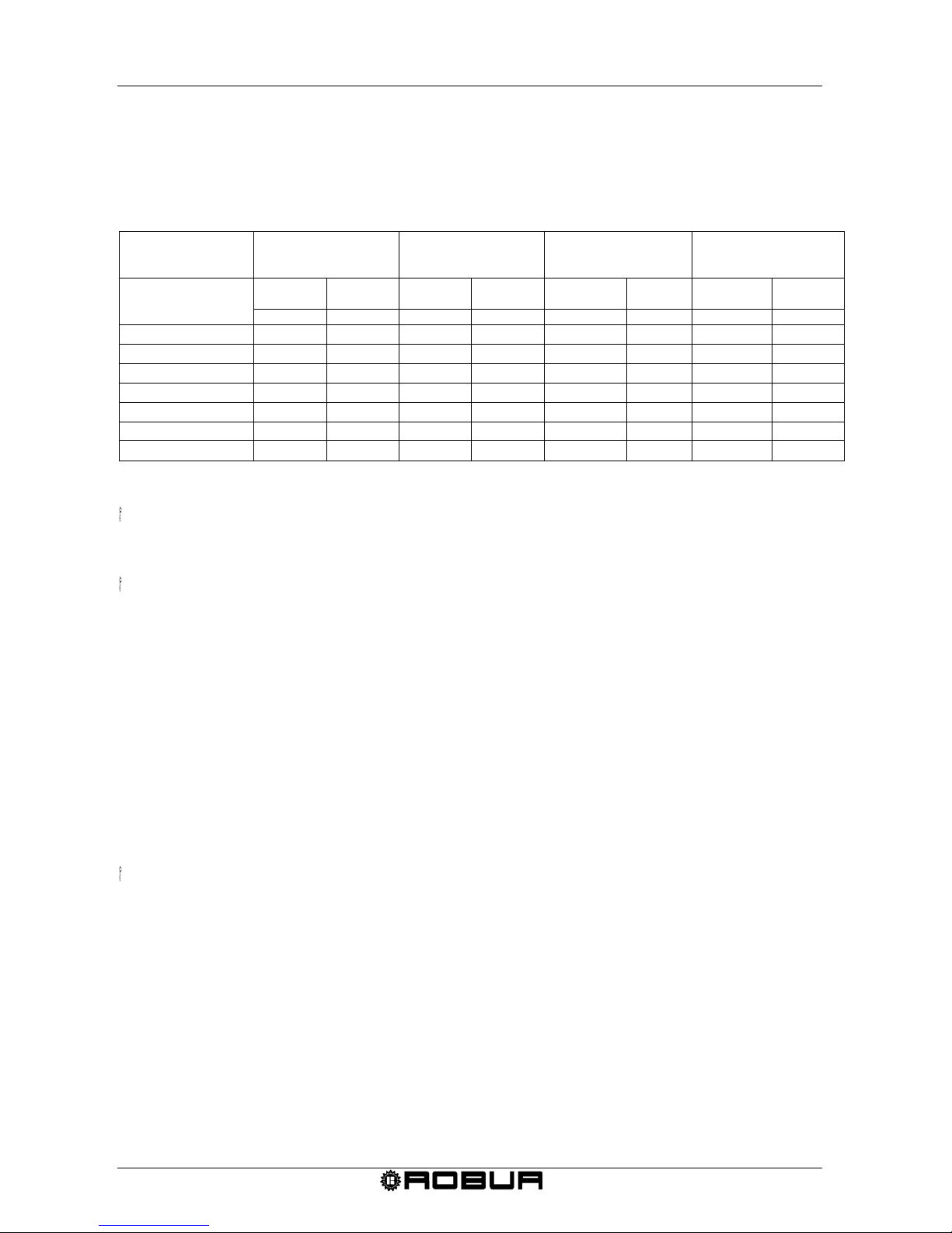
In the Table 10 are listed, depending on the model, the values (in percentage) that could
be set and the appropriate heat input (to be reported on the data plate).
Page 35
Condensing Gas Fired Unit Heaters – G Series: Manual of installation, use and maintenance
32 Ed. 09/2018
Example:
For a heater "model G100", setting a heat input of 86,9 kW, it is needed to set (in the
parameter "PM 05") the value: "90".
NOTE: the value "100" (%) (= value of default) correspond to the Heat Nominal Input of
the heater; the value "0" (%) corresponds to the Minimum heat input of the heater.
"PM 05"
(higher limit of
modulation)
G 30 G 45 G 60 G 100
Value to be set
[%]
Blower
speed
Heat
Input
Blower
speed
Heat
Input
Blower
speed
Heat
input
Blower
speed
Heat
input
[ rpm ]
[ kW ]
[ rpm ]
[ kW ]
[ rpm ]
[ kW ]
[ rpm ]
[ kW ]
100 %
3500
30,0
4850
45,0
5650
58,0
6000
93,0
95 %
3420
29,3
4693
43,5
5468
56,1
5803
89,9
90 %
3340
28,6
4535
42,1
5285
54,3
5605
86,9
85 %
3260
27,9
4378
40,6
5103
52,4
5408
83,8
80 %
3180
27,3
4220
39,2
4920
50,5
5210
80,8
75 %
3100
26,6
4063
37,7
4738
48,6
5013
77,7
70%
3020
25,9
3905
36,2
4555
46,8
4815
74,6
Table 10
Once the heat input of the heater has been set, it is obligatory to update the data
plate by printing the new set value, as for the law UNI EN 1020.
On the data plate of the unit there is space for the installer to mark up with indelible
characters the nominal setting heat input, just before the start up of the unit (UNI EN
1020 law, paragraph 7.1.2).
2.17 END OF SEASON
1. Turn off the appliance (as described in the SHUTDOWN paragraph) and wait for the
fans to stop.
2. Close the gas supply valve on the appliance.
3. If you will not be using the SUMMER OPERATION (VENTILATION ONLY) function,
remove electrical power to the appliance by means of the omni polar switch located
on the power line.
The chronothermostat has a 12 hour battery buffer. If the heater does not have
electrical power, after 12 hours the time and date settings will be lost (however the
temperature and profile settings will remain in memory). To avoid this, do not remove
electrical power from the heater, even during the seasonal shutdown.
Page 36

Condensing Gas Fired Unit Heaters – G Series: Manual of installation, use and maintenance
Ed. 09/2018 33
SECTION 3: PLUMBER INSTALLER
In this section you will find all the necessary indications for installation from a plumbing
point of view for series G.
3.1 GENERAL RULES FOR INSTALLATION OF THE APPLIANCE
Installation must be carried out, according to the manufacturer’s instructions, by a
qualified service engineer;
A qualified service engineer is defined as someone having specific technical
competence in the heating unit components sector.
The units must be installed according to the national and international norms regarding
this type of appliances and applications.
Installation procedures should be as follows:
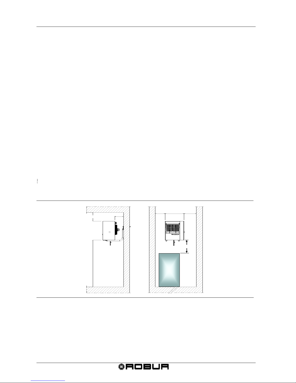
- The minimum distance from the wall behi nd t he uni t mus t be en oug h for air circ ul ation.
The minimum distance from the lateral walls is given by Figure 14 at page 34.
- The distance from the lower part of the heater to any object or structure below it must
be not inferior than 50 cm in order to permit the installation and the service of the
condensing siphon.
- The recommended height from the floor to the heater base is 2.5 to 3.5 m. It is not
recommended to install the appliance under the 2.5 m height (see Figure 14 at page
34).
- To obtain the maximum system efficiency it is advisable to comply with the following
rules:
• install units as close as possible to the work area, taking care that the air flow does not
come directly into the contact with people
• take obstacles into consideration (columns, etc.).
• for better heat distribution in the case of multiple unit installation, create alternate flows
of hot air (see Figure 15);
• in some cases it may be suitable to place the units close to the main doors, so they
can operate as an air barrier when doors are opened.
- Do not install the series G heating units in greenhouses or in environments with a high
degree of humidity or similar atmospheric conditions because they were not designed
for this type of use.
3.2 INSTALLATION SEQUENCE
Install the gas supply lines, the electric power lines and a suitable support bracket for the
unit according the approved installation project.
1. Unpack the unit, carefully checking that it has not been damaged. Every unit is
factory tested before shipment, therefore, if there are damages, report them
immediately to the carrier.
Page 37
Condensing Gas Fired Unit Heaters – G Series: Manual of installation, use and maintenance
34 Ed. 09/2018
2. Install the support bracket. Robur S.p.A. supplies an optional, easy-to-install bracket
specifically designed for each heater.
3. Fasten the heater to the bracket using the screws provided.
4. Make sure that an adequate gas supply from the gas network is provided,
particularly if the unit is supplied with:
Natural gas
Be sure that the pressure of the gas network, with the unit in operation, is set at 20
mbar (204 mm H2O) (allowed tolerance between 17 and 25 mbar).
L.P.G. (Propane – Butane mix)
For the first pressure drop required in the supply, it is advisable to install a pressure
governor near the liquid gas tank so as to reduce the pressure to 1.5 bar. A pressure
governor for a second pressure drop should be placed near the heater to reduce the
pressure to 37 mbar (allowed tolerance between 20 and 45 mbar).
L.P.G. (Pure Propane)
For the first pressure drop required in the supply, it is advisable to install a pressure
governor near the liquid gas tank so as to reduce the pressure to 1.5 mbar. A low
pressure governor for a second pressure drop should be placed near the heater to
reduce the pressure from 1,5 bar to 37 mbar (allowed tolerance between 20 mbar
and 45 mbar).
In the case of doubt, adjust the appli a nc e as f or the propane- butane mix.
5. A gas cock and a pipe union must be provided for gas supply
Figure 14 – Clearances to be respected
350
Min 2,5 m
Max 3,5 m
Min 200 A A
Min 400
330
Object
or
structure
[max height]
500
Page 38
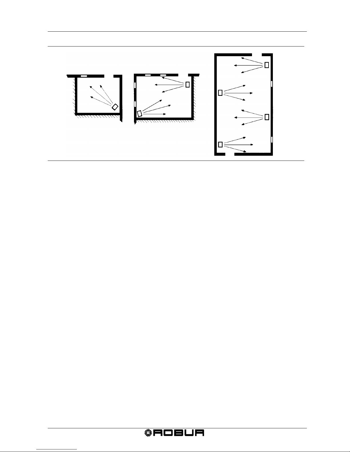
Condensing Gas Fired Unit Heaters – G Series: Manual of installation, use and maintenance
Ed. 09/2018 35
Figure 15 – Sample positioning of the units
3.3 SIZE AND INSTALLATION OF THE AIR INLET / EXHAUST FLUE
The G series gas fired heating units can be installed in one of the following ways:
- C
13
type installation: room sealed combustion circuit. Appliance with inlet air supply
and outlet of exhaust gases with or separate ducts (see Figure 18 and Figure 19 at
page 39) or concentric (see Figure 20 and Figure 21 at page 39 and 40).
- C
33
type installation: type installation; room sealed combustion circuit. Appliance with
inlet air supply and outlet of exhaust gases with, either, concentric or separate ducts
(see Figure 22 and Figure 23 at page 40 and 41).
- B
23
type installation: combustion air taken directly from the room and flue exhaust
gases to the outside. This exhaust flue duct can be either horizontal or vertical. This
type of installation is not sealed regarding the heated room (see from Figure 24 to
Figure 27 starting from page 41).
- C
53
type installation: room sealed combustion circuit; appliance with inlet air supply and
outlet of exhaust gases by using separated ducts and terminals on different walls, for
example, the air inlet duct from the wall behind the appliance and the flue exhaust duct
on the roof (see Figure 28 and Figure 29 at page 43 and 44).
- C
63
type installation: allows installing the certified air inlet/flue exhaust ducts, elbows
and terminals purchased on the market. Moreover, it permits to use the pipe diameters
bigger than 80mm: for example when the installation requir es us i ng the pipe o f the
larger diameter, caused by the longer ducts. With this typology, for the calculus of the
flue/air inlet duct refer to the duct manufacturers data and furthermore to the flue
composition, flue flow and its temperature (see Table 11 at page 36).
In any case use flue pipes according to the approved type of installation you have to do.
The material used for the exhaust fumes must be class W1 UNI EN 1443 and then
adapted to resist the action of the condensate of combustion products from gaseous fuels.
In case you should use different pipes from the ones furnished by the producer, please
assure yourself that these are appropriate for the kind of heater on which they are
installed. You should especially check that the class of temperature of these pipes must
Page 39
Condensing Gas Fired Unit Heaters – G Series: Manual of installation, use and maintenance
36 Ed. 09/2018
be appropriate with the working features of the heater and to the chemical-physical
stability of the system itself.
The combustion products contain a high concentration of water vapour.
Ensure that the fumes are not sucked in by the combustion air intake
because it may cause the unit to malfunction.
To determine a correct size of the flue system its total pressure drop has to be calculated.
The allowed pressure drop in the pipe system depends on the model of the unit (Table 11
at page 36).
The maximum allowed pressure drop for each unit, the losses of the exhaust and air
intake flues regarding the coaxial ducts supplied by manufacturer are shown in Table 12
at page 37 (for Ø 80 and Ø 100) and in Table 13 at page 37 (for Ø 110 and Ø 130).
External terminals pressure losses are negligible since it is very low.
Check the total inlet/outlet pipes pressure losses regarding maximum values given by
Table 11. On the following pages there is an the example of pressure loss calculation and
respective duct project. It must be checked that the total amount of the flue system
pressure losses are within the minimum and the maximum losses allowed for the unit
The maximum lengths of the air inlet and exhaust tubes, in relation to the type of
installation being done, are reported from Figure 18 to Figu r e 29. These lengths are
intended to be APPROXIM ATE val ues for standard installations in which the air supply
pipe and exhaust pipe follow linear paths as seen in the respective figures. If this is not
the case, you must proceed to the calculation to verify the pressure loss (see SAMPLE
CALCULATION).
In the case of horizontal flue pipe installations must meet the following guidelines:
Flue length ≤ m 1: Install the flue pipe with a counter slope of 2 to 3 cm towards the
heater (see Figure 16).
Flue length> 1 m: the condensate produced from the ex haus t pi pe must be
adequately drained by a special collection and disposal system in accordance with
the local norms.
For proper installation of the wall external terminals of the exhaust products of combustion
and combustion air intake see Figure 17.
TECHNICAL DATA FOR THE AIR/EXHAUST SYSTEM
Mod.
Flue temperature
°C
Flue flow rate in
weight
kg/h
CO2 in exhaust %
Max. Allowed Pressure
Loss (Pa)
Natural gas LPG
G 30 82 52
8,5-9,6 9,8-10,7
65
G 45 90 76 100
G 60
85 98 120
G 100 85 158 200
Table 11 – Technical data for air/exhaust sy ste m.
8,5-9,6
8,3-9,0 9,3-10,5
Page 40
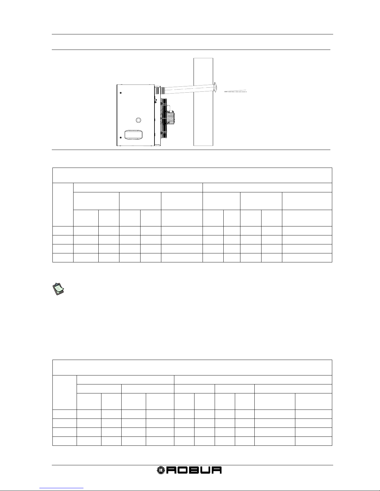
Condensing Gas Fired Unit Heaters – G Series: Manual of installation, use and maintenance
Ed. 09/2018 37
Figure 16 – Counterslope horizontal pipes
TECHNICAL DATA FOR THE CA
LCULATION OF THE AIR/EXHAUST SYSTEM USING Ø 80 OR Ø 100 DUCTS
SUPPLIED BY ROBUR UPON REQUEST
Mod.
Pressure loss Ø 80 components Pressure loss Ø 100 components
duct (Pa/m) 90° elbow (Pa) coaxial (Pa) duct (Pa/m) 90° elbow (Pa) coaxial (Pa)
flue air flue air
wall
(O-SCR012)
flue air flue air
wall
(O-SCR009)
G 30
3,8 2,4 7,6 3,6 15 1.2 0,8 3,5 2 13
G 45 6 4
11 5 20
1,8
1,2
4,8
3,7
18
G 60
8 6,5 17 10 N.P. 5 2,6 8 5 N.P.
G 100
22 17 36 24 N.P. 9 4 18 11 N.P.
Table 12 – Data for the calculation of the air/flue system with Ø 80 or Ø 100 ducts
N.P.= INSTALLATION NOT POSSIBLE
For each T-shaped piece, consider an increment of length equal to 3.0 metres of the
pipe on which it was assembled (ex. if the T-shaped piece was assembled on a 2
metre long flue pipe, when calculating the pressure loss the entire 5 metres of the
flue pipe must be considered).
For each 45° elbow, consider an increment of length equal to 1.2 metres of the pipe
on which it was assembled (ex. if 45° elbow was assembled on a 2 metre long air
pipe, when calculating the pressure loss the entire 3.2 metres of the air pipe must be
considered).
TECHNICAL DATA FOR THE CALCULATION OF THE AIR/FLUE SYSTEM USING Ø 110 OR Ø 130 DUCTS
SUPPLIED BY ROBUR UPON REQUEST
Mod.
Pressure loss Ø 110 components Pressure loss Ø 130 components
duct (Pa/m) 90º elbow (Pa) duct (Pa/m) 90° elbow(Pa) Coaxial (Pa)
flue air flue air flue air flue air
wall
(O-SCR011)
roof
(O-KTC001)
G 30 1,0 0,55 2,9 1,5 0,6 0,2 1,6 0,5 6 8
G 45
1,4 0,8 4 2 0,9 0,3 2 0,8 9 12
G 60 2,5 1,7 6,6 4,1 1,8 1 4 1,8 15 22
G 100 7 3 15 8 3,5 1,5 10 3 32 35
Table 13 – Data for the calculation of the air/flue system with Ø 110 or Ø 130 ducts
2-3%
Page 41
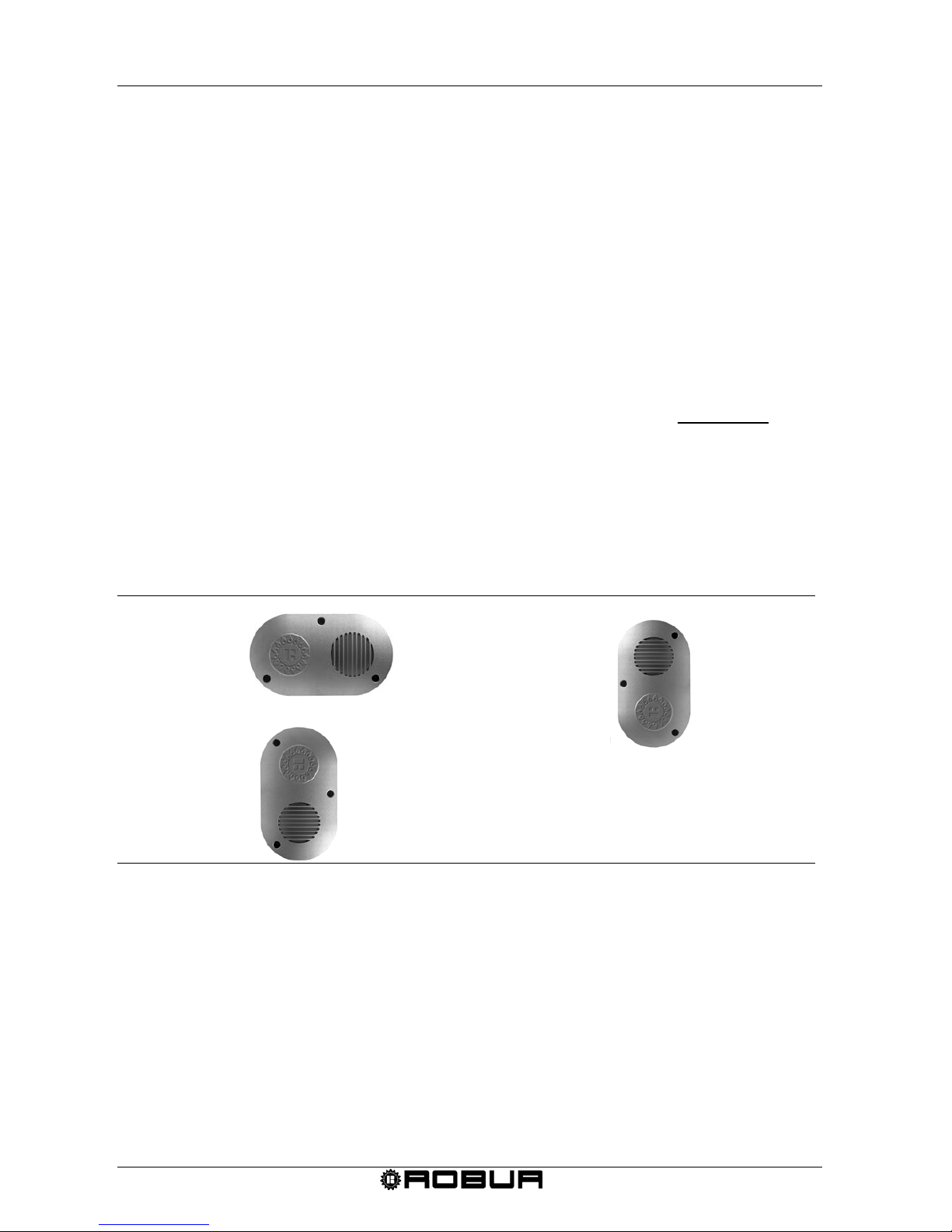
Condensing Gas Fired Unit Heaters – G Series: Manual of installation, use and maintenance
38 Ed. 09/2018
SAMPLE CALCULATION
Let’s use the installation of a G 100 for this example. The air/flue system is made using
the following separate Ø 80 ducts :
- 7 meters Ø 80 flue pipe
- 1 elbow 90° of Ø 80 on the flue pipe
- 3 meters of Ø 80 air pipe
The calculation can therefore be done keeping in mind that the maximum allowed
pressure loss is 200 Pa (see Table 11).
Quantity Pressure loss
Flue pipe Ø 80 6 m x 22 Pa =
132,0 Pa +
Elbow 90º 1 m x 36 Pa =
36,0 Pa +
Air pipe Ø 80
3 m
x
17
Pa = 51,0
Pa
=
Total pressure loss 219,0 Pa
The total pressure loss of the system is greater than the max. allowed pressure loss (219
Pa GREATER than 200 Pa) therefore the installation is NOT POSSIBLE.
The installation can be done if one of the following actions is taken:
- reduce the air/flue duct length;
- increase the duct diameter using Ø100 ducting.
Figure 17 – Wall terminal positioning
1 = EXHAUST FLUE
2 = COMBUSTION INLET AIR
RECOMMANDE
D POSITION
2
1
ALLOWED
POSITION
2
1
FORBIDDEN
POSITION
2
1
Page 42
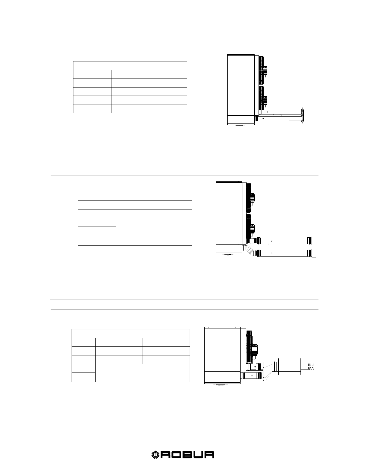
Condensing Gas Fired Unit Heaters – G Series: Manual of installation, use and maintenance
Ed. 09/2018 39
MAXIMUM ALLOWED LENGTHS (m)
AIR PIPE FLUE PIPE
G 30 10 10
G 45 10 10
G 60 8 8
G 100 5 5
Figure 18 – C13 installation type with separate pipes Ø 80.
MAXIMUM ALLOWED LENGTHS (m)
AIR PIPE FLUE PIPE
G 30
20 20
G 45
G 60
G 100 14 14
Figure 19 –C13 installation pipe with separate pipes Ø 110.
MAXIMUM ALLOWED LENGTHS
(m)
AIR PIPE FLUE PIPE
G 30 8 8
G 45 8 8
G 60
INSTALLATION
NOT POSSIBLE
G 100
Figure 20 – C13 coaxial wall type installation with Ø 80 ducts.
C13 INSTALLATION W/ SEPARATE Ø 80 DUCTS
ATTENTION: The above mentioned lengths are intended for installations in which the air and exhaust ducts
are on linear paths as represented in the figure. If this is not the case it is necessary to
proceed and verify the pressure losses (see SAMPLE CALCULATION).
TOP VIEW
INSTALLATION C13 C/SEPARATE PIPES Ø 110
ATTENTION: The above mentioned lengths are intended for installations in which the air and exhaust ducts
are on linear paths as represented in the figure. If this is not the case it is necessary to
proceed and verify the pressure losses (see SAMPLE CALCULATION).
It 's important to fit the external terminals to avoid the recirculation of flue gases into the combustion air intake
pipe.
TOP VIEW
C13 COAXIAL WALL INSTALLATION WITH Ø 80
DUCTS
ATTENTION: The above mentioned lengths are intended for installations in which the air and exhaust ducts
are on linear paths as represented in the figure. If this is not the case it is necessary to proceed and verify
the pressure losses (see SAMPLE CALCULATION).
TOP VIEW
Page 43
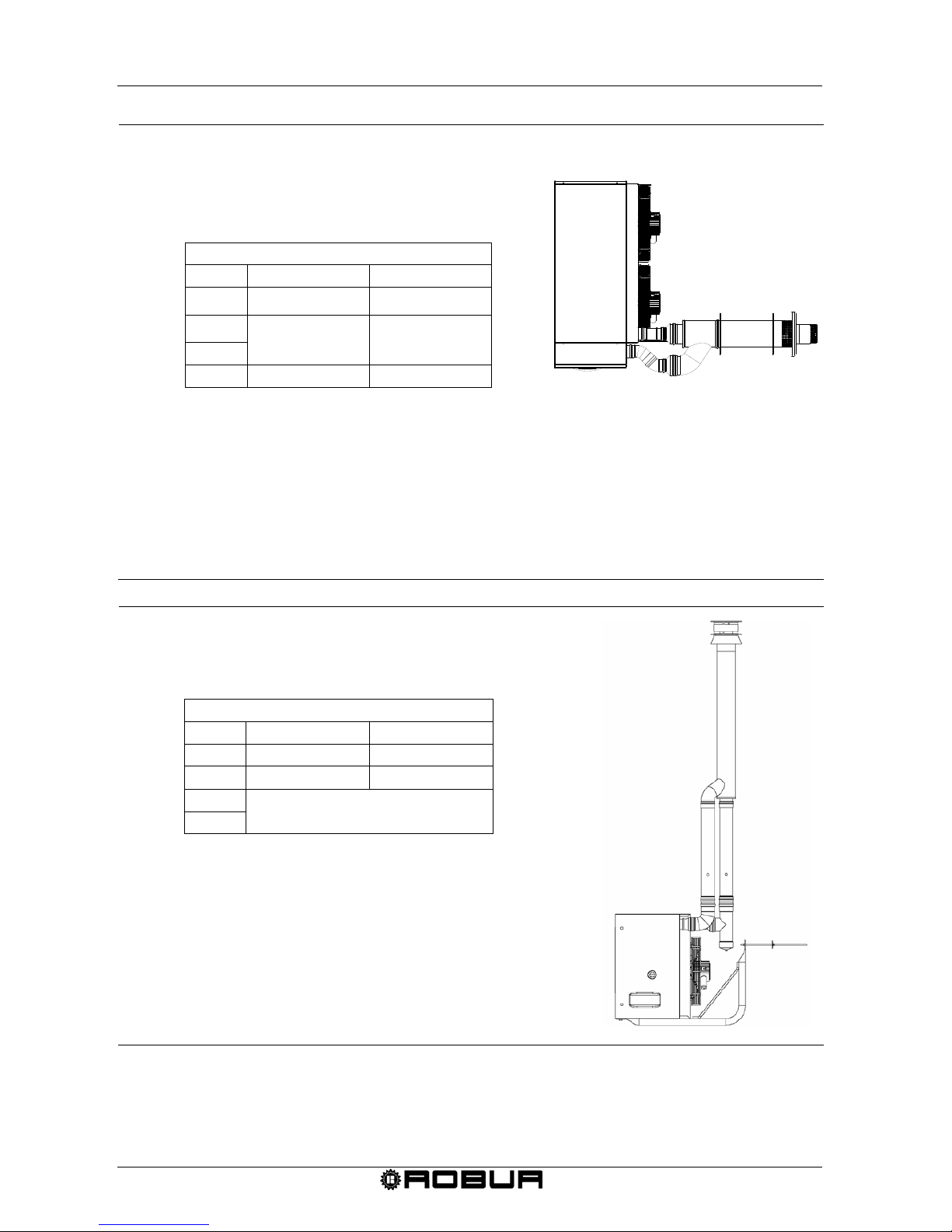
Condensing Gas Fired Unit Heaters – G Series: Manual of installation, use and maintenance
40 Ed. 09/2018
MAXIMUM ALLOWED LENGTHS (m)
AIR PIPE FLUE PIPE
G 30 30 30
G 45
20 20
G 60
G 100
18
18
Figure 21 – C13 coaxial wall type installation with Ø 130 ducts
MAXIMUM ALLOWED LENGTHS
(m)
AIR PIPE FLUE PIPE
G 30 20 20
G 45 18 18
G 60
INSTALLATION
NOT POSSIBLE
G 100
Figure 22 – C33 coaxial roof type installation with Ø 100 ducts
C13 COAXIAL WALL INSTALLATION WITH
Ø 130 DUCTS
ATTENTION: The above mentioned lengths are intended for installations in which the air and exhaust ducts
are on linear paths as represented in the figure. If this is not the case it is necessary to
proceed and verify the pressure losses (see SAMPLE CALCULATION).
TOP VIEW
C33 COAXIAL ROOF INSTALLATION (cod. O-SCR009) WITH
Ø 100 DUCTS
ATTENTION:
The above mentioned lengths are intended for
installations in which the air and exhaust ducts are
on linear paths as represented in the figure. If this is
not the case it is necessary to proceed and verify the
pressure losses (see SAMPLE CALCULATION).
Page 44
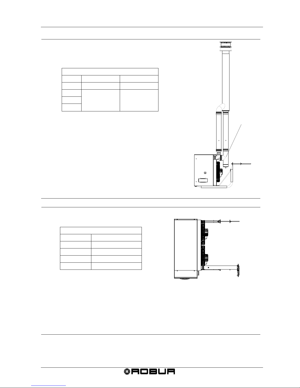
Condensing Gas Fired Unit Heaters – G Series: Manual of installation, use and maintenance
Ed. 09/2018 41
MAXIMUM ALLOWED LENGTHS (m)
AIR PIPE FLUE PIPE
G 30 30 30
G 45
20 20
G 60
G 100
Figure 23 – C33 coaxial roof type installation with Ø 130 ducts
MAXIMUM ALLOWED LENGTHS (m)
FLUE PIPE
G 30 17
G 45 15
G 60 14
G 100 8
Figure 24 – B23 type installation with Ø 80 flue pipe
C33 COAXIAL ROOF INSTALLATION (Cod. O-KTC001) WITH
Ø 130 DUCTS
ATTENTION: The above mentioned lengths
are intended for
installations in which the air and exhaust ducts are
on linear paths as represented in the figure. If this is
not the case it is necessary to proceed and verify the
pressure losses (see SAMPLE CALCULATION).
CONDENSATE
TRAP
B23 INSTALLATION WITH Ø 80 FLUE PIPE
ATTENTION: The above mentioned lengths are intended for installations in which the air and exhaust ducts
are on linear paths as represented in the figure. If this is not the case it is necessary to
proceed and verify the pressure losses (see SAMPLE CALCULATION).
TOP VIEW
Page 45
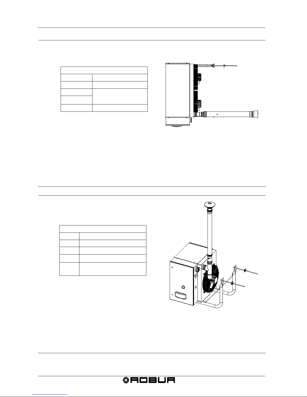
Condensing Gas Fired Unit Heaters – G Series: Manual of installation, use and maintenance
42 Ed. 09/2018
MAXIMUM ALLOWED LENGTHS (m)
FLUE PIPE
G 30 30
G 45
25
G 60
G 100 20
Figure 25 – B23 type installation with Ø 110 flue pipe
MAXIMUM ALLOWED LENGTHS
(m)
FLUE PIPE
G 30 14
G 45 13
G 60 11
G 100
INSTALLATION
NOT POSSIBLE
Figure 26 – B23 type installation with Ø 80 roof flue pipe.
B23 INSTALLATION WITH Ø 80 ROOF FLUE PIPE
B23 INSTALLATION WITH Ø 110 FLUE PIPE
TOP VIEW
ATTENTION: The above mentioned lengths are intended for installations in which the air and exhaust ducts
are on linear paths as represented in the figure. If this is not the case it is necessary to
proceed and verify the pressure losses (see SAMPLE CALCULATION).
ATTENTION: The above mentioned lengths are intended for installations in which the air and exhaust ducts
are on linear paths as represented in the figure. If this is not the case it is necessary to
proceed and verify the pressure losses (see SAMPLE CALCULATION).
Page 46
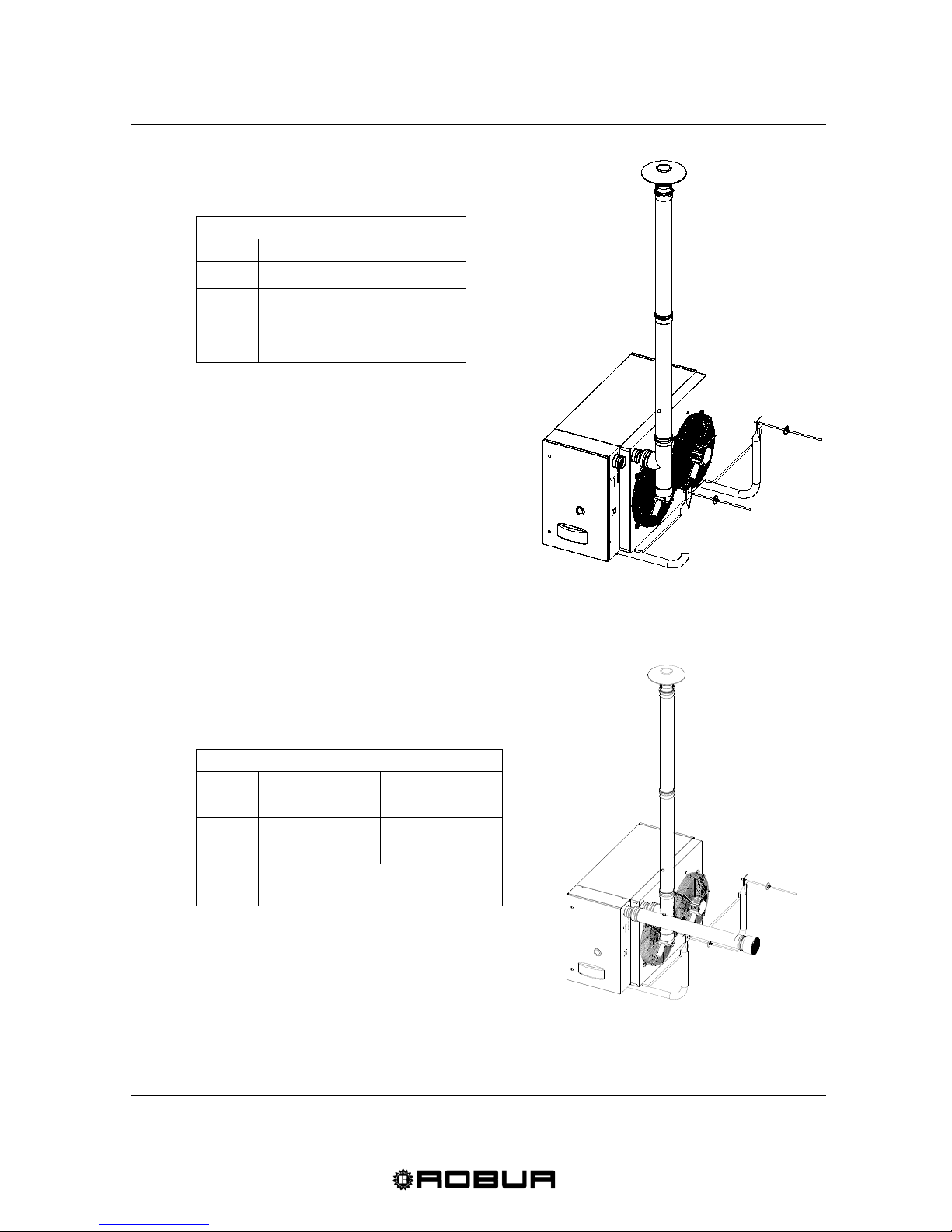
Condensing Gas Fired Unit Heaters – G Series: Manual of installation, use and maintenance
Ed. 09/2018 43
MAXIMUM ALLOWED LENGTHS (m)
FLUE PIPE
G 30 30
G 45
25
G 60
G 100 20
Figure 27 – B23 type installation with Ø 110 roof flue pipe
MAXIMUM ALLOWED LENGTHS (m)
AIR PIPE
FLUE PIPE
G 30 1 13
G 45 1 12
G 60 1 10
G 100
INSTALLATION
NOT POSSIBLE
Figure 28 – C53 type installation with Ø 80 pipes
C53 INSTALLATION WITH Ø 80 PIPES
ATTENTION: The above mentioned lengths are intended for installations in which the air and exhaust ducts
are on linear paths as represented in the figure. If this is not the case it is necessary to
proceed and verify the pressure losses (see SAMPLE CALCULATION).
B23 INSTALLATION WITH Ø110 ROOF FLUE PIPE
ATTENTION:
The above mentioned lengths are
intended for install ations in which the air
and exhaust ducts are on linear paths as
represented in the figure. If this is not the
case it is necessary to proceed and verify
the pressure losses (see SAMPLE
CALCULATION).
Page 47
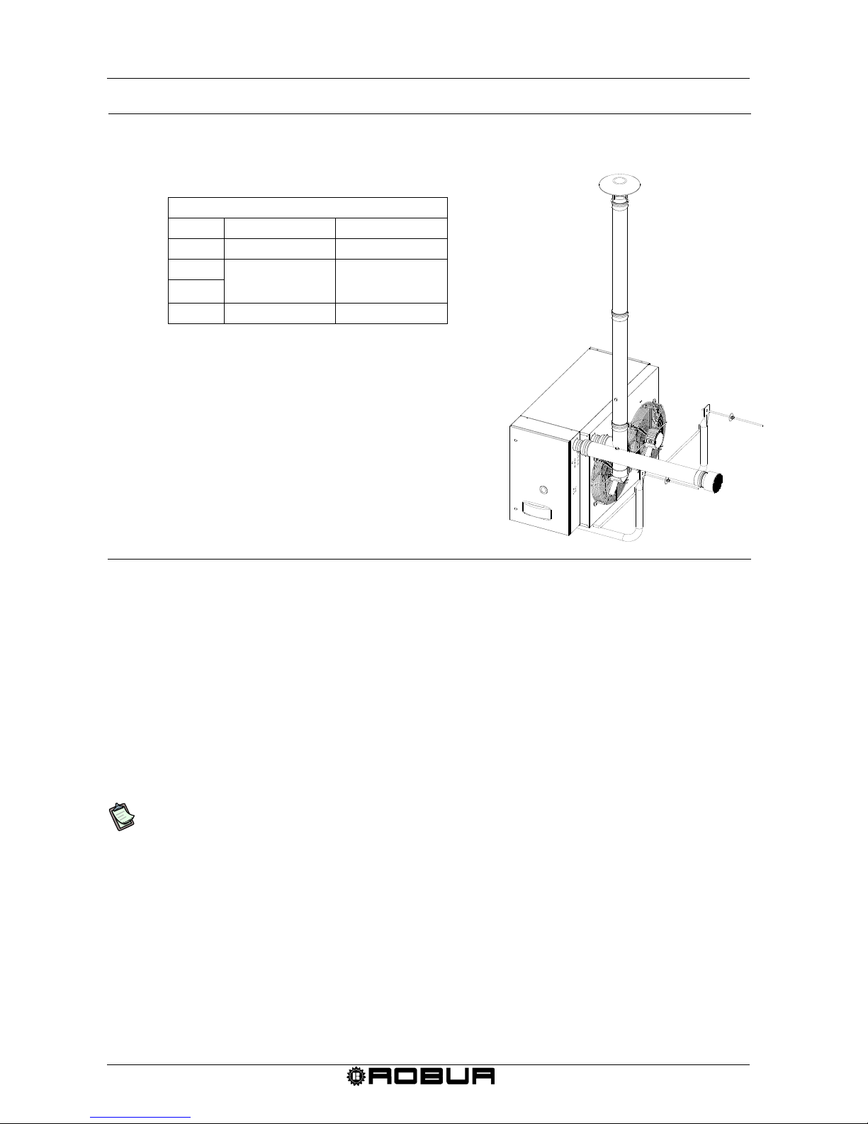
Condensing Gas Fired Unit Heaters – G Series: Manual of installation, use and maintenance
44 Ed. 09/2018
MAXIMUM ALLOWED LENGTHS (m)
AIR PIPE FLUE PIPE
G 30 1 30
G 45
1 25
G 60
G 100 1 18
Figure 29 – C53 type installation with Ø 110 pipes
3.4 CONDENSATE DRAINAGE
G series Gas Fired Unit Heaters are equipped with a condensing drainage kit to be
connected (by the installer) to the suitable outlet situated in the lower part of the heater.
Connect the two parts of the kit (see inside the bag): unscrew upper ring of the " siphon
condensing discharge", insert the "neck ring of condensing discharge connection" in
aluminium (with the connection in external position) and screw the ring.
At this point, screw the assembled from the "neck ring connection" side in aluminium at
the outlet of the heater (Figure 30).
The outlet situated in the lower part of the unit has been designed in the way to
remain usable even in case of installation of support bracket (as accessory).
Regulate the siphon leaving the discharge connection facing the route of the exhaust pipe
(Figure 31). The connection of the discharge to the collecting system must be at
atmospheric pressure, it means as dripping in a siphoned tray connected to the collecting
system, installing a suitable neu tr al i ser of the c ond ens at e, in accordance with the
installation rules.
Regarding the tray pipes of the condensate, they must be utilised suitable materials long
term resistant to mechanical, thermal and chemical stresses of the condensate, as
stainless steel pipes or in PP plastic material. Do not utilise iron or copper pipes, materials
easily consumable by the acidity of the condensate.
C53 INSTALLATION WITH Ø 110 PIPES
ATTENTION:
The above mentioned lengths are
intended for installations in which the air
and exhaust ducts are on linear paths as
represented in the figure. If this is not the
case it is necessary to proceed and verify
the pressure losses (see SAMPLE
CALCULATION).
Page 48
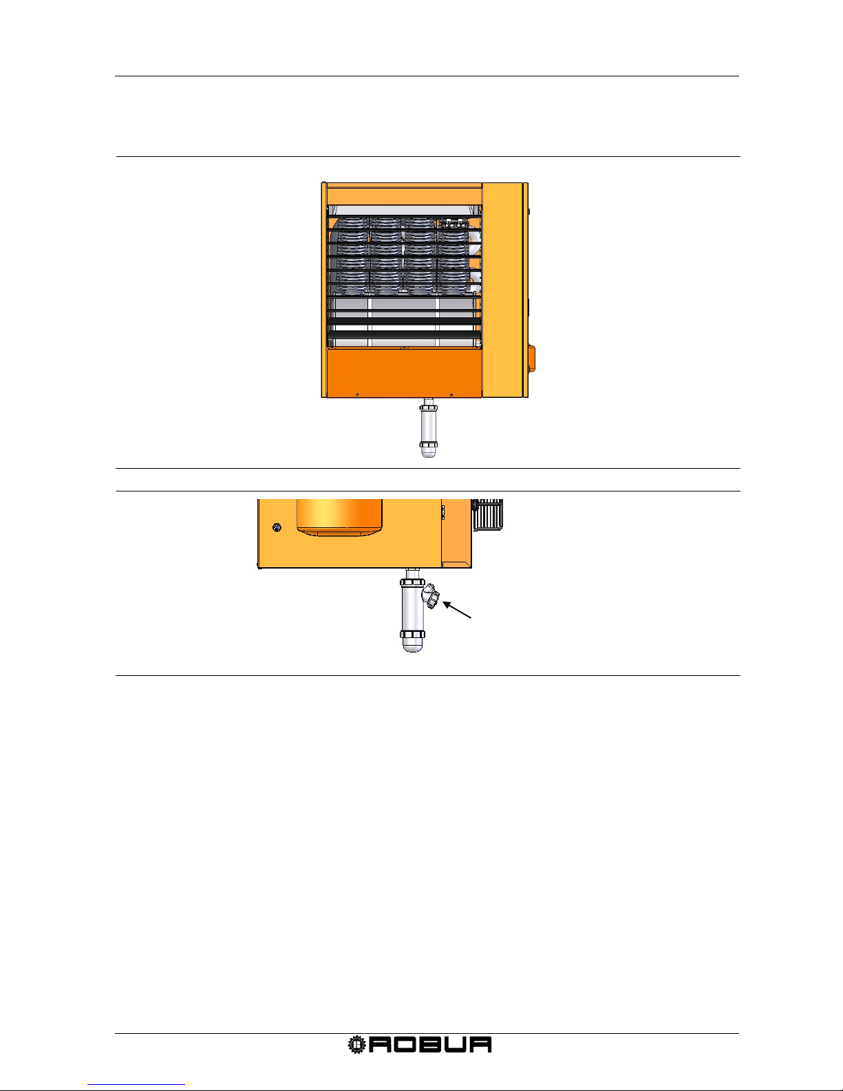
Condensing Gas Fired Unit Heaters – G Series: Manual of installation, use and maintenance
Ed. 09/2018 45
In case of absence of specific technical norms, please refer to local legislations.
Figure 30 – Positioning of siphon condensate discharge.
Figure 31 – Detail of the installation of the condensate siphon discharge.
Connection for the condensate
discharge (by the installer)
connection for the inspection of the
Page 49
Condensing Gas Fired Unit Heaters – G Series: Manual of installation, use and maintenance
46 Ed. 09/2018
SECTION 4: ELECTRICAL INSTALLER
In this section you will find all the information necessary for the electri c al connec t ions o f
the G series heating units.
4.1 HOW TO CONNECT THE HEATER TO THE ELECTRICAL SYSTEM
Requirements: The heater must be installed.
The electrical connecti ons must be do ne by a qualified service engineer. Be fore
beginning this operation, cut off the electrical supply.
1. Checking that the voltage supply is 230/50Hz single-phase.
2. Carry out the electrical connections according to the installation wiring diagram (see
Figure 33 at page 49) wire type is H05 VVF 3x1,5 mm2 with a maximum external
diameter of 8.4 mm.
3. When connecting, ensure that the earth wire is longer than the live wires, so that it
will be the last wire to break if the supply cable is stretched, thus ensuring a good
earth continuity.
The electrical safety of the unit is attained only when the unit itself is correctly
connected and efficiently grounded according to the existing safety standards. Do
not use gas tubes to earth electrical apparatus.
4. The unit should be connected to the electric supply line by means of an omnipolar
switch with a minimum contact opening of 3 mm. An omnipolar switch is a '’Double
pole isolating switch’’. This means that when the switch is opened, both contacts are
disconnected.
The control wires (especially those connected to the chronothermostat) must be
protected from interference created by power wires. This can be achieved, for
example, using wire protectors or by using conduits that are separate from those
containing the power cables.
4.2 HOW TO CONNECT THE CHRONOTHERMOST AT TO THE HE ATER
The electrical connecti ons must be do ne by a qualified service engineer. Be fore
beginning this operation, shut off the electrical supply.
For the installation of the chronothermostat, proceed as follows:
1. It is recommended to place the sensor at about 1.5 m from the floor , protected
against air draughts, direct exposure to sun rays and direct heat sources (lamps, hot
air flows from the unit itself, etc.). If possible, DO NOT place the chronothermostat
on walls bordering the outside, to avoid false temperature readings and therefore
system operation. IF THE ROOM CHRONOTHERMOSTAT IS PROPERLY
INSTALLED, UNWANTED STARTING AND STOPPING OF THE SYSTEM WILL
Page 50
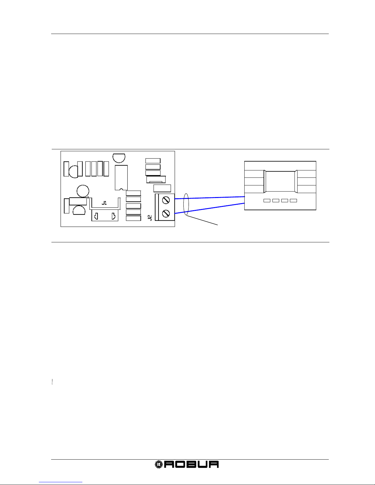
Condensing Gas Fired Unit Heaters – G Series: Manual of installation, use and maintenance
Ed. 09/2018 47
BE AVOIDED AND ADEQUATE ROOM COMFORT WILL BE ENSURED. If this is
not possible, shield the chronothermostat by placing a sheet of insulating material
(cork, polystyrene, etc.) between it and the wall.
2. Drill holes in the wall corresponding to the fastening points of the chronothermostat.
3. Fasten the chronothermostat with 2 expansion screws.
4. Chronothermostat is supplied wired to the dialog board with 5 meters cables and
must be installed at suitable position. For lengths greater than 5 meters use an
unshielded bipolar 0,75 mm2 section cable with maximum resistance for 5
Ω
conductor (use a shielded cable if the installation has strong electrical disturbances).
In any case, the cable must not be longer than 30 meters.
Figure 32 – Connection of chronothermostat and dialog board
4.3 UNIT OPERATION WITH EXTERNAL CONSE NT
In winter, multiple units can be controlled with a single external consent (ex. programmer
clock) by removing the electric jumper on the terminals marked by the symbol “radiator”
and connecting the external consent to the terminals themselves (see Figure 34 at page
51).
In summer, multiple units can be controlled with a single external consent (ex.
programmer clock) by removing the electric jumper on the terminals marked by the
symbol “fan” and connecting the external consent to the terminals themselves (see Figure
34 at page 51).
In any case, each unit must be connected to the related chronothermostat, from
which the operating consent must also be provided (AND logic).
Opening the external consent contact will deactivate the unit, regardless of what is
foreseen by the chronothermostat.
For more information regarding unit operation and use in this mode, directly contact
Robur Pre-Sales service on +39 035/888.111.
CABLE 2 X 0,75 mm2 MAXIMUM
RESISTANCE PER CONDUCTOR 5 Ω
MAXIMUM LENGTH 30 METRI
CHRONOTHERMOSTAT
DIALOG BOARD LOCATED ON THE CONTROL
CIRCUIT IN POSITION X13
Page 51
Condensing Gas Fired Unit Heaters – G Series: Manual of installation, use and maintenance
48 Ed. 09/2018
4.4 REMOTE SIGNALLING OF THE ANOMALIES
Electric connections must be made by professionally qualified personnel. In any
case, before making any electric connection, cut off the electrical supply.
The possible anomalies that could arise during normal unit operation can be identified
through their “error code” that appears on the chronothermostat display (for more
information see Table 7).
The operating anomalies can also be signalled remotely by connecting a led to terminal J9
on the LC23 board (output 230V – 50Hz, see diagram of Figure 33 at page 49).
The maximum length of the remote signal cable is 200 metres.
If a led turns on, as described in Table 14, this means there is an anomaly.
Release may also be done remotely. To do this, a button must be connected to the J11
terminals on the LC23 board (output 230V – 50Hz, see diagram in Figure 33 at page 49).
Closing the contact resets the anomaly.
The maximum length of the remote signal cable is 200 metres.
ANOMALY
ACCENSIONE LED
UNIT LOCK OUT FIXED
LIMIT THERMOSTAT FLASHING (ON = 4 SECONDS, OFF = 1 SECOND)
(1)
OTHER TYPE OF ANOMALY
FLASHING (ON = 1 SECOND, OFF = 4 SECONDS)
(1)
Table 14
1 AFTER 72 CONTINUOUS HOURS OF FLASHING, THE STATUS BECOMES FIXED
Page 52
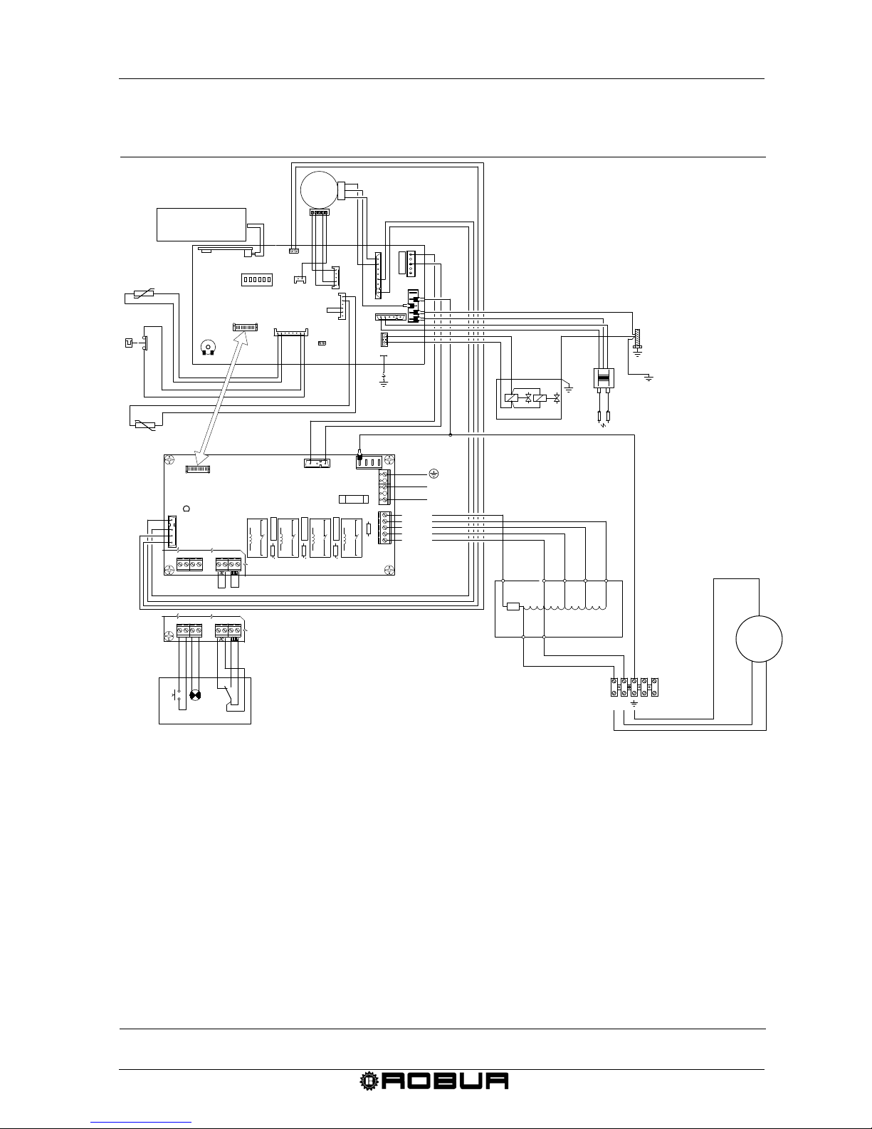
Condensing Gas Fired Unit Heaters – G Series: Manual of installation, use and maintenance
Ed. 09/2018 49
4.5 INSTALLATION WIRING DI AGRAM
Figure 33 – Installation wiring diagram of G 30, G45, G60
1 2 3 4 5 6
N
X12
REMOTE UNIT
INTERFACE
N
SF
~
L
1
5
C
L1
P
REMOTE
CONTROL
X15
X3
X17
X16
X22
X18
N
TR
P3
N
X19
FUSE 2A
T3
T3
T2
T1
L1
N1
X7
Portina
P1
T5
X7
EV
RLZ
AC
FUSE 6.3A
X13
L
N
GND
X5
X6
X3
X1
K4
K3
K2
X7
X10
X11
X9
X8
C
1
2
3
4
F1
K1
X7
X10
X11
X9
COM
MIN
MED/MIN
MED/MAX
MAX
L
N
X9
SCH1
SCH2
IN 230V 50Hz
GND
V1
~
M
M-1
230
0
TRF 1
N
TL
S
STF
2
754
6
8
3
1
3 9
5
2
10
8
1
FN1
FL1
FN2
FL2
LD1
SF Soffiatore - Blower - Souffleur - Geblauser - dmychadlo - ПОДДУВ. УСТРОЙСТВО ДЛЯ ДЫМОУДАЛЕНИЯ
SCH1 Scheda di controllo - Control board - Carte de controlle - Steuerplatine - řídící deska - СХЕМА УПРАВЛЕНИЯ
SCH2 Scheda motori - Control board motors - Carte controlle moteurs - Steuerplatine motoren - řídící deska ventilátoru - СХЕМА ДВИГАТЕЛЕЙ
S Sonda limite - Overheat probe - Sonde temperature - Brennerwachter - čidlo teploty výměníků - ДАТЧИК ТЕПЛООБМЕННИКА
TL Termostato limite - Overheat thermostat - Thermostat limite- Sicherheitstemperaturbegrenzer - limitní termostat - ПРЕДЕЛЬНЫЙ ТЕРМОСТАТ
STF Sonda fumi - Flue Probe - Sonde gaz de combustion - Abgassonde - čidlo teploty spalin - ДАТЧИК ТЕМПЕРАТУР ГАЗОВ
RL Rilevazione fiamma - Detector flame - Detection flamme - Flammenuberwachung - elektroda snímače plamene - КОНТРОЛь ПЛАМЕНИ
EV Elettrovalvola gas - Gas valve - Electrovanne gaz - Gasmagnetventil - plynový ventil - ЭЛЕКТРОГАЗОВЫЙ КЛАПАН
AC Elettrodo accensione - Ignition - Electrode d'allumage - Zundelektrode - zapalovací elektroda - ЭЛЕКТРОД РОЗЖИГА
TR1 T rasformatore d'accensione - Ignition transformer - Trasformateur d'allumage - Zundtransformator - autotransformátor ventilátoru -
PT
ТРАНСФОРМАТОР ДЛЯ РОЗЖИГА
Piolo di terra - Ground - Mise a la terre - Endung
V1-2
V1-2 V entilatore - Fan motor - Ventilateur - Ventilator - motor vzduchového ventilátoru - ВЕНТИЛЯТОР (n.2 G100)
C
L1
P
Consenso ventilazione/riscaldamento - Fan/heating consent - Ventilation/chauffage consensuns -
Zustimmung lüftung/heizung - kontakt letního provozu/kontakt zimního provozu РАЗРЕШ. СИГНАЛ ВЕНТИЛЯЦИИ/РАЗРЕШ. СИГНАЛ ОТОПЛЕНИЯ
Segnale di blocco - Lock signal - Signal lock - Locksignal - doutnavka signalizující poruchu - СИГНАЛ БЛОКИРОВКИ
Pulsante di sblocco - Reset - Touche release - Reset taste - reset chyby - КНОПКА ДЛЯ РАЗБЛОКИРОВК И
Page 53
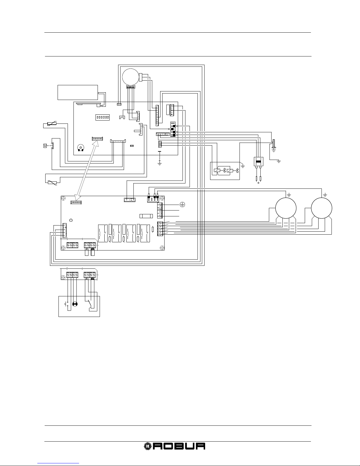
Condensing Gas Fired Unit Heaters – G Series: Manual of installation, use and maintenance
50 Ed. 09/2018
Figure 34 – Installation wiring diagram of G 100
1 2 3 4 5 6
N
X12
REMOTE UNIT
INTERFACE
N
SF
L
1
5
C
L1
P
REMOTE
CONTROL
~
X15
X3
X17
X16
X22
X18
N
TR
P3
N
X19
FUSE 2A
T3
T3
T2
T1
L1
N1
X7
Portina
P1
T5
X7
EV
RLZ
AC
COM
MIN
MED/MIN
MED/MAX
MAX
FUSE 6.3A
X13
L
N
GND
X5
X6
X3
X1
L
N
K4
K3
K2
X7
X10
X11
X9
X8
C
1
2
3
4
F1
K1
X7
X10
X11
X9
X9
SCH1
SCH2
IN 230V 50Hz
GND
V1
V2
~
~
TL
S
STF
2
754
6
8
3
1
LD1
SF Soffiatore - Blower - Souffleur - Geblauser - dmychadlo - ПОДДУВ. УСТРОЙСТВО ДЛЯ ДЫМОУДАЛЕНИЯ
SCH1 Scheda di controllo - Control board - Carte de controlle - Steuerplatine - řídící deska - СХЕМА УПРАВЛЕНИЯ
SCH2 Scheda motori - Control board motors - Carte controlle moteurs - Steuerplatine motoren - řídící deska ventilátoru - СХЕМА ДВИГАТЕЛЕЙ
S Sonda limite - Overheat probe - Sonde temperature - Brennerwachter - čidlo teploty výměníků - ДАТЧИК ТЕПЛООБМЕННИКА
TL Termostato limite - Overheat thermostat - Thermostat limite- Sicherheitstemperaturbegrenzer - limitní termostat - ПРЕДЕЛЬНЫЙ ТЕРМОСТАТ
STF Sonda fumi - Flue Probe - Sonde gaz de combustion - Abgassonde - čidlo teploty spalin - ДАТЧИК ТЕМПЕРАТУР ГАЗОВ
RL Rilevazione fiamma - Detector flame - Detection flamme - Flammenuberwachung - elektroda snímače plamene - КОНТРОЛь ПЛАМЕНИ
EV Elettrovalvola gas - Gas valve - Electrovanne gaz - Gasmagnetventil - plynový ventil - ЭЛЕКТРОГАЗОВЫЙ КЛАПАН
AC Elettrodo accensione - Ignition - Electrode d'allumage - Zundelektrode - zapalovací elektroda - ЭЛЕКТРОД РОЗЖИГА
PT Piolo di terra - Ground - Mise a la terre - Endung
V1-2
V1-2 V entilatore - Fan motor - Ventilateur - Ventilator - motor vzduchového ventilátoru - ВЕНТИЛЯТОР (n.2 G100)
C
L1
P
Consenso ventilazione/riscaldamento - Fan/heating consent - Ventilation/chauffage consensuns -
Zustimmung lüftung/heizung - kontakt letního provozu/kontakt zimního provozu РАЗРЕШ. СИГНАЛ ВЕНТИЛЯЦИИ/РАЗРЕШ. СИГНАЛ ОТОПЛЕНИЯ
Segnale di blocco - Lock signal - Signal lock - Locksignal - doutnavka signalizující poruchu - СИГНАЛ БЛОКИРОВКИ
Pulsante di sblocco - Reset - Touche release - Reset taste - reset chyby - КНОПКА ДЛЯ РАЗБЛОКИРОВК И
Page 54
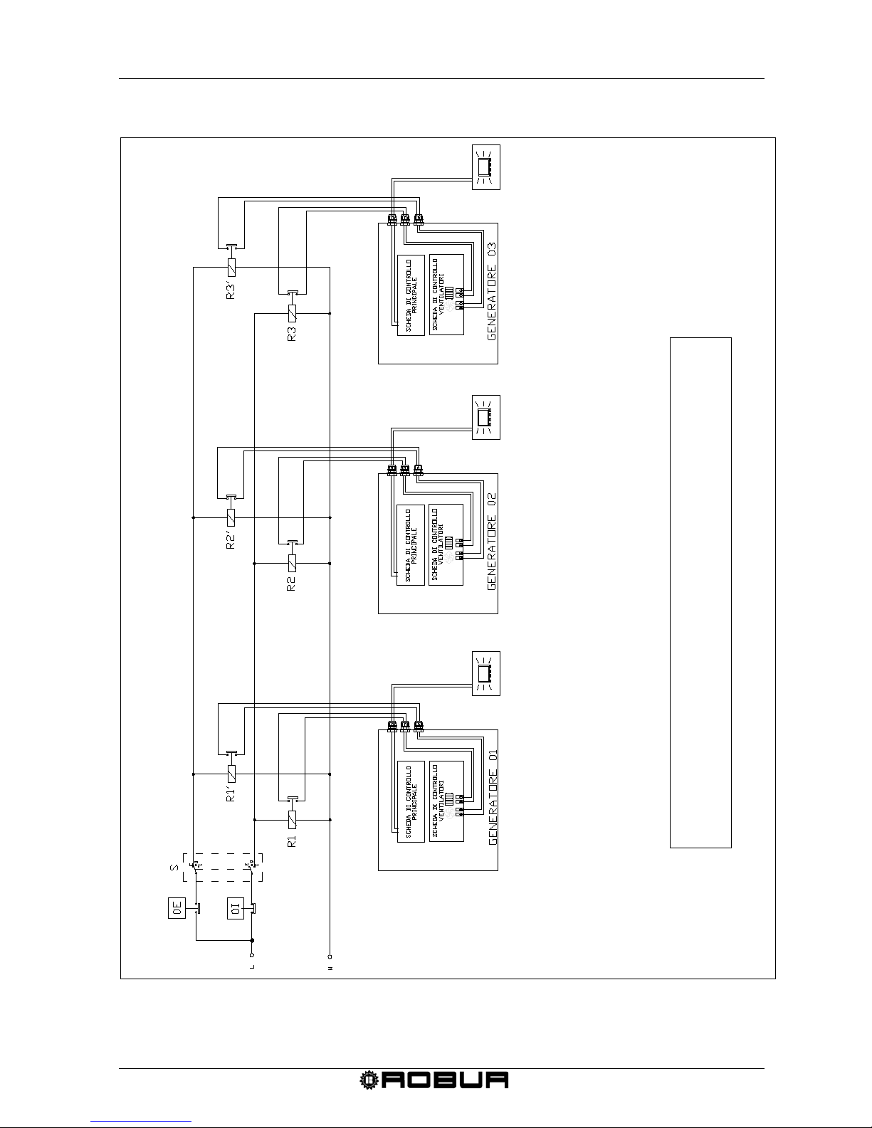
Condensing Gas Fired Unit Heaters – G Series: Manual of installation, use and maintenance
Ed. 09/2018 51
WIRING DIAGRAM FOR MULTIPLE HEATER WITH ONE PROGRAMMER
Figure 35 – Wiring diagram for controlling multiple units with external consent
OE SUM MER UNIT OPERATION CONSENT
OI
WINTER UNIT OPERATION CONSENT
R1-3 REL
AY FOR WINTER UNIT OPERATION CONSENT
R1’-3’
RELAY FOR SUMMER UNIT OPERATION CONS
ENT
S SUMMER/WINTER SWITCH
ATTENTION
Each unit must be connected to the related
chronothermostat
Page 55
Condensing Gas Fired Unit Heaters – G Series: Manual of installation, use and maintenance
52 Ed. 09/2018
SECTION 5: ASSISTANCE AND MAINTENANCE
In this section you will find the indications necessary for the technicians to regulate the
gas valve, gas conversion as well as other instructions regarding maintenance.
5.1 START UP OF THE UNIT
The start up of the unit has to be done by a qualified service engi neer following the
instructions here below :
• Data plate are the same as the ones of power and gas network;
• The set of pressure is compatible with the power of the heater.
Once it has been checked the correct installation and the correct installation data, the
Authorised Technical Service could proceed with the start up of the unit and verify the
correct functioning of it. In particular it must c heck :
• That static and dynamic pressure of the gas network will be in the demanded range;
• That set values of gas valve will be the same as the ones in Table 16, at page 53.
• That the connection of combustion air and flue exhaust will be correctly made as per
local laws.
• That the functioning of the fl ue ex haus t will be correct .
If set values of gas valve will not be the same as the ones indicated in Table 16 of
page 53, it is necessary to set the combustion parameters as reported in the
paragraph 5.2.
The heater is delivered natural gas (G20) fired as standard. In case of installations
with a different type of gas, it is necessary to do the conversion of gas (paragraph
5.3) and the setting of parameters (paragraph 5.2).
5.2 HOW TO REGULATE THE GAS VALVE
For the correct functioning of the K series heating units, the calibration values of the gas
valve must be like that indicate d in Table 16. The gas valve of the heating unit is precalibrated by the manufacturer. If adjustment is necessary, proceed as described below.
Requirements: The installed heater must be connected to the electrical and gas
networks.
Regulation of the gas valve must be done by a qualified service engineer.
1. After having removed the relative holding screws, connect a pressure gauge to
pressure jack A (see Figure 35 at page 53).
If a pressure switch is used, connect the gas valve’s pressure jack A to the +
(positive) inlet of the pressure gauge.
Page 56
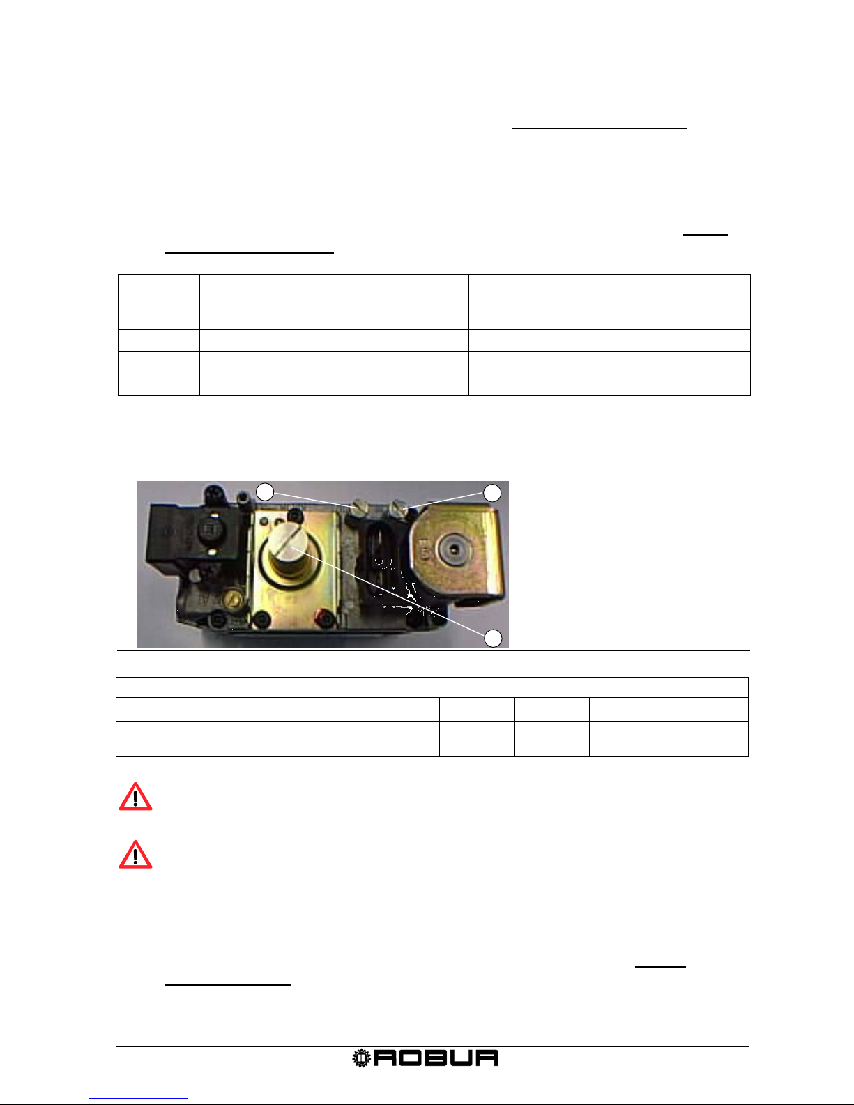
Condensing Gas Fired Unit Heaters – G Series: Manual of installation, use and maintenance
Ed. 09/2018 53
2. Turn on the heater and set chromothermostat on level 3 (maximum power) and
wait the necessary time for the flame to stabilize (about 5 minutes).
3. Set the chronothermostat to minimum power/output (level 1) using the ▼button.
4. Enter the information mode by pressing and holding the IP button for at least 3
seconds. The word INFO will appear on the display. Pressing the OK button
selecting RPM string it displays the blower speed that must be checked at level 1
(minimum power/outpu t) . the value have to be as indicated Table 15.
BLOWER SPEED AT LEVEL 1
MINIMUM POWER
BLOWER SPEED AT LEVEL 3
MAXIMUM POWER
G30
1900
3500 ± 150
G45
1700
4850 ± 150
G60
2000
5650 ± 150
G100
2050
6000 ± 150
Table 15
5. With the door open, turn the off-set regulation screw C (see Figure 35 at page 53)
until the correct nominal value is obtained as reported in Table 16.
Figure 36 – Valve Sit 822 Novamix.
NOMINAL OFF-SET VALUES
G 30
G 45 G 60 G 100
OFF-SET (mbar)
(Pa)
-0,15
-15
-0,15
-15
-0,05
-5
-0,05
-5
Table 16 – Nominal off-set values.
Nominal setting value has never to be higher than -0,05 mbar and lower than 0,2 mbar.
Check the burner. It must not have reddened areas.
6. Disconnect the pressure gauge and replace the seal screw of pressure jack A.
7. Turn the unit on and off two or three times in order to verify that the calibration is
stable.
8. Close the door of the instrument panel, set up by chronothermostat Level 3
(maximum power), check CO2 flue value that have to be as indicated on Table 11
pag.36.
A C B
A PRESSURE OFF-SET
REGULATION SET
B GAS REGULATI O N SCREW
C OFF-SET REGULATION
Page 57
Condensing Gas Fired Unit Heaters – G Series: Manual of installation, use and maintenance
54 Ed. 09/2018
9. Check that the values of static and dynamic gas pressure, with the heaters
operating at level 3, correspond to the paragraph 3.2 INSTALLATION SEQUENCE
on page 33 (with lower gas pressure value CO2 flue value will also be the minimum
values).
5.3 CONVERSION TO ANOTHER TYPE OF GAS
Requirements: The installed heater must be connected to the electrical and gas
networks.
Qualified engineers must carry out this operation. Wrong and careless assembly of
the gas circuit may cause dangerous gas leakage. Use adequate seals for all
connections.
If the type of gas on the identification label does not correspond to the one that will be
used, the unit must be converted and adapted to the type of gas you wish to use.
For this operation proceed as follows:
1. Cut off the power and gas supply.
2. Loosen the four fastening screws from the gas flange (see Figure 36).
3. Remove the gas pipe/flange assembly (see Figure 37).
4. Remove the sealing gasket, being careful not to damage or lose it (see Figure 38).
5. Replace the nozzle (see Table 17) and reposition the sealing gasket.
6. Re-assembly the gas pipe/flange using the four fastening screws.
7. Modify the position of minidip n. 5, located on the main control circuit: ON position if
LPG units, OFF position if natural gas units (Figure 40).
8. Check that the OFF-SET value corresponds to that indicated in Table 16 at page 53.
If the value does not correspond, proceed with the calibration as indicated in
paragraph 5.2 "HOW TO REGULATE THE GAS VALVE ".
9. Replace the adhesive label indicating the type of gas for which the unit is set with a
new label indicating the type of gas actually used.
NATURAL GAS and L.P.G nozzles
G 30
G 45
G 60
G 100
Natural gas (G20) diameter (mm)
codice
6,60
155
7,20
164
7,20
239
11,20
247
LPG (G31) diameter (mm)
codice
5,10
160
6,00
186
Table 17 – G series nozzle data (diameters and codes).
5,70
252
Page 58
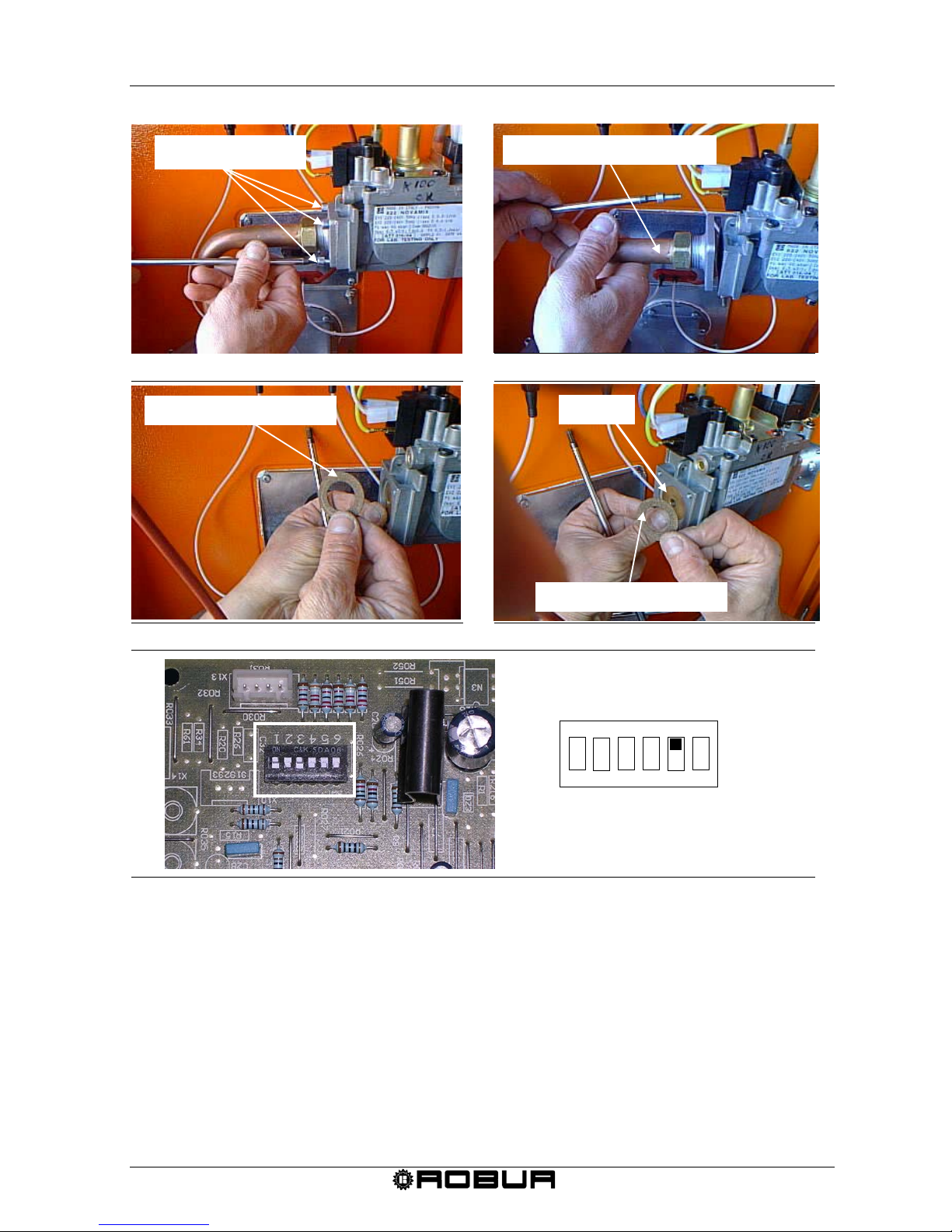
Condensing Gas Fired Unit Heaters – G Series: Manual of installation, use and maintenance
Ed. 09/2018 55
Fig
ure 37 – Gas flange fastening screws.
Figure
38 – Gas pipe/flange assembly.
Fig
ure 39 – Sealing gasket.
Fig
ure 40 – Nozzle replacement.
Fig
ure 41 – Minidip position on main control circuit
5.4 MAINTENANCE
Regular maintenance is always a source of savings and safety.
Maintenance for heating units must be done, preferably at the beginning of winter, by
qualified service engineers.
For a correct and extended operation, an general cleaning of the appliance is
recommended at least once a year (with special attention given to the heat exchangers
and ventilation grills) and combustion tests according to that foreseen by the specific
regulations.
1 2 3
4
5
6
ON: LPG units
OFF: NATURAL GAS units
ON
OFF
FASTENING SCREW
GAS PIPE/FLANGE ASSEMBLY
SEALING GASKET
NOZZLE
SEALING GASKET
Page 59

Condensing Gas Fired Unit Heaters – G Series: Manual of installation, use and maintenance
56 Ed. 09/2018
The intervention of the temperature limit thermostat is ALWAYS an indication of an
irregular condition. Before resetting it is therefore a good idea to investigate the
reasons why the unit overheated. In there are frequent shutdowns, contact ROBUR
Customer Assistance.
Page 60
Item Symbol Value Unit Item Symbol Value Unit
Rated heating capacity
P
rated,h
30,0 kW
Useful efficiency at rated
heating capacity (*)
η
nom
87,7 %
Minimum capacity
P
min
15,0 kW
Useful efficiency at
minimum capacity (*)
η
pl
94,9 %
At rated heating
capacity
el
max
0,205 kW Envelope loss factor
F
env
0,0 %
At minimal capacity
el
min
0,155 kW
Ignition burner power
consumption (*)
P
ign
0,0 kW
In standby mode
el
sb
0,000 kW
Emissions of nitrogen
oxides (*) (**)
NO
x
mg/kWh input
energy (GCV)
Emission efficiency
η
s,flow
91,8 %
Seasonal space heating
energy efficiency
η
s,h
82,0 %
Contact details
(*) Not required for electric warm air heaters.
(**) From 26 September 2018.
Capacity
Useful efficiency
Electric power consumption (*)
Other items
Robur SPA
Via Parigi 4/6
I-24040 Zingonia (BG)
Type of fuel: [gas/liquid/electricity]
gas
Table 9
Information requirements for warm air heaters
Model(s): Information to identify the model(s) to which the information relates:
B1 warm air heater: [yes/no]
C2 warm air heater: [yes/no]
C4 warm air heater: [yes/no]
G 30
no
no
no
COMMISSION REGULATION (EU) 2016/2281
Page 61
Item Symbol Value Unit Item Symbol Value Unit
Rated heating capacity
P
rated,h
45,0 kW
Useful efficiency at rated
heating capacity (*)
η
nom
86,9 %
Minimum capacity
P
min
15,0 kW
Useful efficiency at
minimum capacity (*)
η
pl
94,0 %
At rated heating
capacity
el
max
0,330 kW Envelope loss factor
F
env
0,0 %
At minimal capacity
el
min
0,280 kW
Ignition burner power
consumption (*)
P
ign
0,0 kW
In standby mode
el
sb
0,000 kW
Emissions of nitrogen
oxides (*) (**)
NO
x
mg/kWh input
energy (GCV)
Emission efficiency
η
s,flow
93,7 %
Seasonal space heating
energy efficiency
η
s,h
85,0 %
Contact details
Type of fuel: [gas/liquid/electricity]
gas
Table 9
Information requirements for warm air heaters
Model(s): Information to identify the model(s) to which the information relates:
B1 warm air heater: [yes/no]
C2 warm air heater: [yes/no]
C4 warm air heater: [yes/no]
G 45
no
no
no
COMMISSION REGULATION (EU) 2016/2281
(*) Not required for electric warm air heaters.
(**) From 26 September 2018.
Capacity
Useful efficiency
Electric power consumption (*)
Other items
Robur SPA
Via Parigi 4/6
I-24040 Zingonia (BG)
Page 62
Item Symbol Value Unit Item Symbol Value Unit
Rated heating capacity
P
rated,h
58,0 kW
Useful efficiency at rated
heating capacity (*)
η
nom
87,4 %
Minimum capacity
P
min
19,3 kW
Useful efficiency at
minimum capacity (*)
η
pl
94,2 %
At rated heating
capacity
el
max
0,580 kW Envelope loss factor
F
env
0,0 %
At minimal capacity
el
min
0,550 kW
Ignition burner power
consumption (*)
P
ign
0,0 kW
In standby mode
el
sb
0,000 kW
Emissions of nitrogen
oxides (*) (**)
NO
x
mg/kWh input
energy (GCV)
Emission efficiency
η
s,flow
94,1 %
Seasonal space heating
energy efficiency
η
s,h
84,8 %
Contact details
(*) Not required for electric warm air heaters.
(**) From 26 September 2018.
Capacity
Useful efficiency
Electric power consumption (*)
Other items
Robur SPA
Via Parigi 4/6
I-24040 Zingonia (BG)
Type of fuel: [gas/liquid/electricity]
gas
Table 9
Information requirements for warm air heaters
Model(s): Information to identify the model(s) to which the information relates:
B1 warm air heater: [yes/no]
C2 warm air heater: [yes/no]
C4 warm air heater: [yes/no]
G 60
no
no
no
COMMISSION REGULATION (EU) 2016/2281
Page 63
Item Symbol Value Unit Item Symbol Value Unit
Rated heating capacity
P
rated,h
93,0 kW
Useful efficiency at rated
heating capacity (*)
η
nom
87,4 %
Minimum capacity
P
min
31,7 kW
Useful efficiency at
minimum capacity (*)
η
pl
95,2 %
At rated heating
capacity
el
max
1,000 kW Envelope loss factor
F
env
0,0 %
At minimal capacity
el
min
0,750 kW
Ignition burner power
consumption (*)
P
ign
0,0 kW
In standby mode
el
sb
0,000 kW
Emissions of nitrogen
oxides (*) (**)
NO
x
mg/kWh input
energy (GCV)
Emission efficiency
η
s,flow
92,9 %
Seasonal space heating
energy efficiency
η
s,h
84,7 %
Contact details
Type of fuel: [gas/liquid/electricity]
gas
Table 9
Information requirements for warm air heaters
Model(s): Information to identify the model(s) to which the information relates:
B1 warm air heater: [yes/no]
C2 warm air heater: [yes/no]
C4 warm air heater: [yes/no]
G 100
no
no
no
COMMISSION REGULATION (EU) 2016/2281
(*) Not required for electric warm air heaters.
(**) From 26 September 2018.
Capacity
Useful efficiency
Electric power consumption (*)
Other items
Robur SPA
Via Parigi 4/6
I-24040 Zingonia (BG)
Page 64

Robur is dedicated to dynamic progression
in research, development and promotion
of safe, environmentally-friendly, energy-efficiency products,
through the commitment and caring
of its employees and partners.
Robur Mission
Robur Spa
advanced heating
and cooling technologies
Via Parigi 4/6
24040 Verdellino/Zingonia (Bg) Italy
T +39 035 888111 F +39 035 4821334
www.robur.com [email protected]
Codice: D-LBR565 Rev.J 18MCMSDC025 20/09/2018
 Loading...