

Rob Papen QUAD User Manual
User Guide
Powered by RPCX

Rob Papen QUAD 2
Welcome
QUAD is the first Rack Extension synthesizer built from the ground up for Reason by
the Rob Papen team. It features two oscillators with a seemingly simple arsenal of
classic waveforms. The sonic palette is huge though, through the vast modulation
possibilities that QUAD has to offer.
The oscillators can be combined through many cross modulation functions –
generating a wide range of harmonics. The next steps in the sound sculpting are the
Phase Distortion and Wave Shaper. These tools are brought to life by four XY-Pads,
which can be moved through an extensive modulation matrix. The movements can be
recorded as automation direc tl y into Reason’s sequencer.
QUAD’s oscillators are complemented by two top notch analogue modelled filters, an
arpeggiator and two high quality effects processors.
Welcome to the new refreshing synthesizer QUAD – only in Reason!
Rob Papen and the RPCX team, October 2014

Rob Papen QUAD 3
Patches and Mod Section
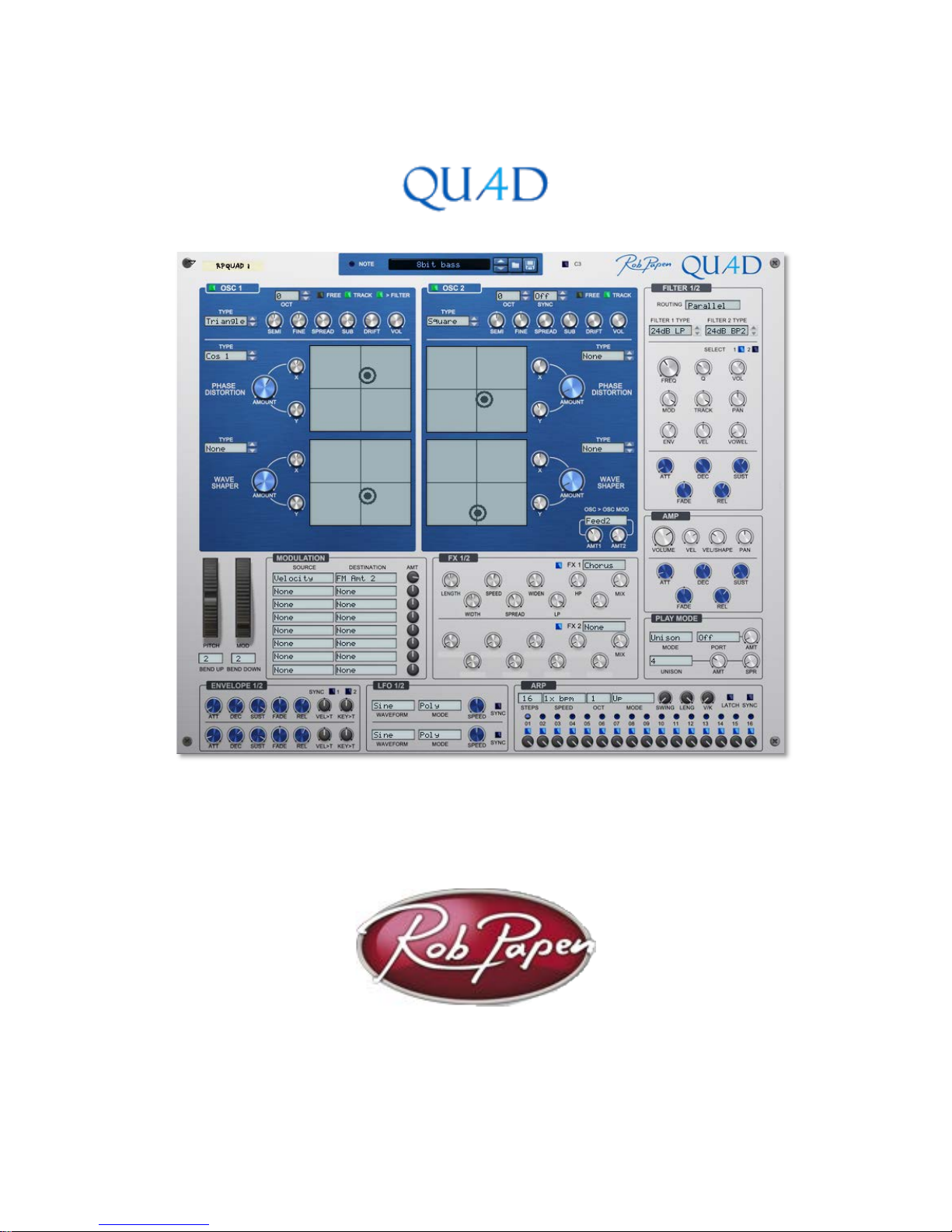
At the top of the QUAD Panel you find the Patch section and modulation controls.
Patch Controls
QUAD uses the standard Reason Patch controls. A click on the Patch menu displays a list
of patches in the current folder. The up and down buttons take you through all the
available patches one by one.
The Folder button opens the patch browser and lets you select a new folder.
The Save Patch button, allows saves the current patch.
The C3 button will plays a single note (C3) allowing you to preview or audition the sound
while you are editing the patch.
Pitch Bend and Mod Wheel
Towards the bottom left of the QUAD panel are the Pitch Bend and Mod Wheels.
The pitch bend wheel bends the pitch up and down and jumps back to its centre position
as soon as you release it. The Bend Down and Up controls set the maximum pitch bend
range. The maximum setting is 48 semitones (4 octaves) up and down
The Mod Wheel generates a modulation signal when you move the wheel up. The Mod
Wheel controller can be patched to any target through the modulation matrix.
Rob Papen QUAD 4
Oscillators
An oscillator is a tone generator. It is the first building block in the sound construction
process. The frequency setting of the oscillator determines the pitch of the sound. The
selected waveform defines the sound’s tonal character, or timbre. QUAD uses up to 2
oscillators in per voice (note played).
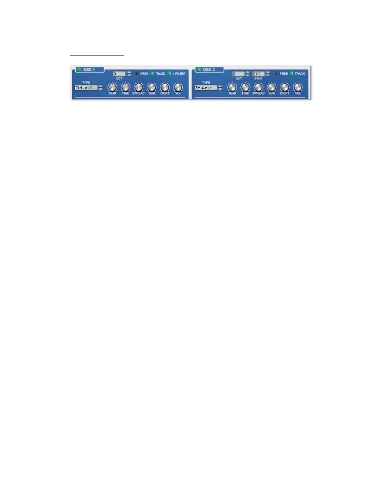
Oscillator On/Off
Pressing the LED-style buttons in the lab el area will turn the corresponding oscillator On and
Off.
Waveform Type
Use the display next to the On / Off button to select the wave-type or waveform used by the
oscillator. QUAD offers a number of classic waveforms: Sine, Square, Triangle, Saw, White
Noise and Pink Noise.
Free
The Free button is used to select the reset-behaviour of the oscillator. If Free is turned off, the
oscillator waveform is reset to its zero phase position each time you play a note. When Free
is turned on, the oscillator is free running; i.e. it is not reset when you play a note. In Free
mode the attack is less pronounced, which may be useful for pad sounds.
Track
The track switch ena bles and disables keyboard tracking. It controls whether the pitch of the
oscillator follows the keyboard or is fixed regardless of the note played.
Octave
The octave control sets the base pitch of the oscillator in octave steps. An octave is
equivalent to 12 semitones. The range of this control is from -2 octaves to +2 octaves..
Semi
Semi sets the coarse tuning of the oscillator in semitones from 48 semitones (-4 octaves) to
+48 semitones (+4 octaves).
Fine
Fine controls the fine-tuning of the oscillator in cents, from -100 cents to +100 cents.
Spread
Spread adds multiple oscillators to the main oscillator with a slightly higher and slightly lower
pitch than the main oscillator. In practice it fattens up the sound. The spread control sets the
difference in oscillator pitch and higher settings will make the effect more pronounced.
Rob Papen QUAD 5
Sub
Sub controls the volume of the sub-oscillator. The sub-oscillator is tuned to one octave below
the oscillator. The sub-oscillator knob lets you select two different waveforms. A counter
clockwise position produces a sinus waveform. Turn it clockwise and it produces a square
waveform. The centre position turns the sub-os ci ll ator of f.
Drift
Drift adds slight irregular variations’ to the oscillator pitch. This can make a sound live lier and
is an essential ingredient for when you want to simulate the behaviour of older analogue
synthesizers that operate to a certain extent unstable and temperature dependent electronic
circuits.
Volume
This control sets the volume of the oscillator in decibels. When the oscillator is used as the
modulator for frequency or ring modulation, it controls the modulation amount.
Filter (Oscillator 1 Only)
The Filter switch allows you to disable the oscillator output to the filter. This may be useful
when you are using Oscillator 1 as a modulation source rather than a sound source as is the
case with FM and ring modulation configurations. Typically, you will want to leave this switch
on so that oscillator 1 sound flows through the filter.
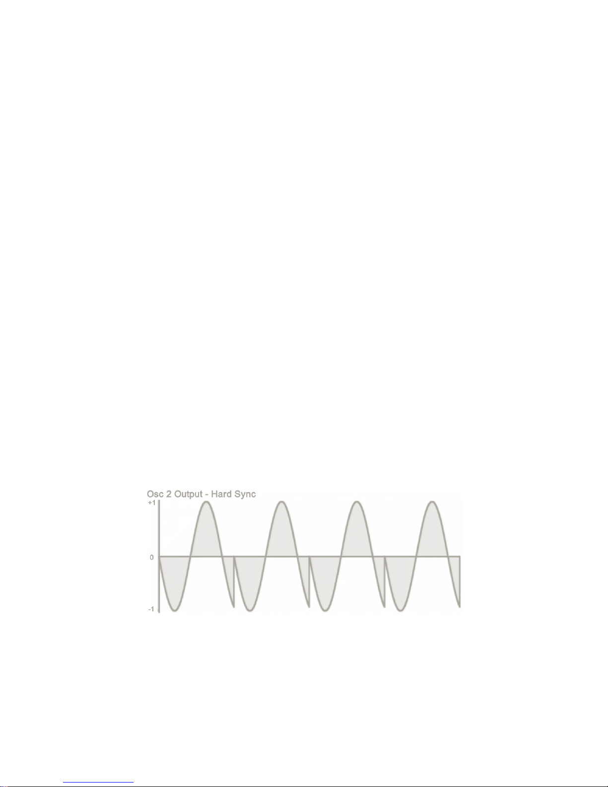
Sync (Oscillator 2 Only)
The Sync control allows you to synchronise (Sync) the oscillator 2 Pitch to the pitch of
Oscillator 1. In Hard Sync mode, Oscillator 2’s waveform is reset every time Oscillator 1
waveform ends its cycle. This essentially cuts of the Oscillator 2 waveform and resets it to
zero, in sync with oscillator 1. Because of the reset, the oscillator 2 waveform will undergo
abrupt changes in its shape. These abrupt changes are audible as additional overtones
(harmonics). The pitch control of oscillator 2 has now become a harmonics control.
In the example below, Oscillator 2 is hard synced to Oscillator 1 where Oscillator 1 is tuned 3
semitones below Oscillator 2. When Oscillator 1 completes its cycle, you can see Oscillator 2
being reset to its initial position, resulting in a (harmonic) spike towards the end of its
wave cycle. This is what generates the additional harmonics.
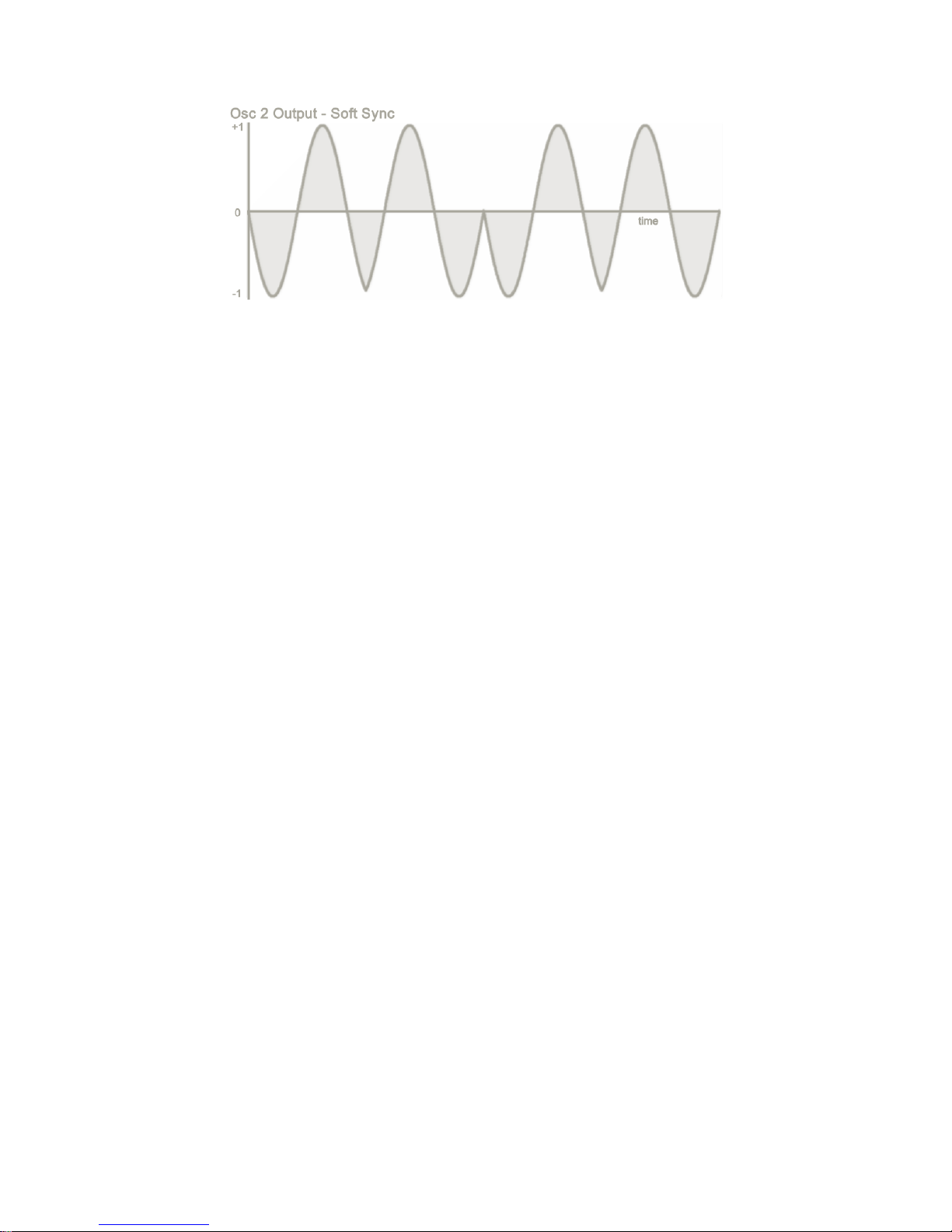
In Soft Sync mode, Oscillator 2’s waveform is also coupled to Oscillator 1’s wave cycle, but in
a much more subtle way. When oscillator 1 finishes its wave cycle, it reverses the synced
oscillator 2 waveform direction Oscillator 2 retains its own pitch, but the reversal of its
waveform introduces additional overtones in the oscillator output. It is a much more subtle
effect than hard sync.
Rob Papen QUAD 6
Rob Papen QUAD 7
Oscillator Modulation Functions
QUAD has a number of different modulation types that allow oscillator 1 to control oscillator 2
and vice versa. Each of the modulation function has Amt 1 and Amt 2 controls to set specific
parameters for each modulation function type.
This chapter lists the modulation functions and the role of the Amt 1 and Amt 2 controls. In
many cases, the effect of the modulation function is illustrated with waveform graphics. As the
sonic impact of the modulation functions can sometimes be unpredictable, we suggest that
you experiment with each modulation function and make yourself familiar with the Amt 1 and
Amt 2 controls.
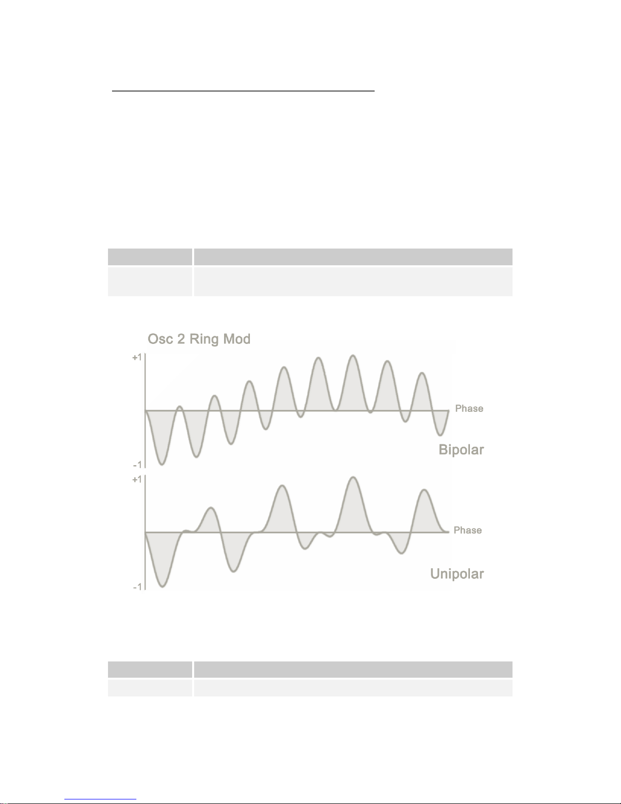
Ring Modulation (Ring)
Ring modulation multiplies oscillator 1 with oscillator 2 to create a new waveform.
Amt 1
Sets the amount of ring modulation.
Amt 2
Sets the balance between the bipolar range (-1 to 1) and unipolar range
(0 to 1) of the modulation signal (oscillator 1).
The difference between bipolar and unipolar ring modulation, is displayed in the following
picture:
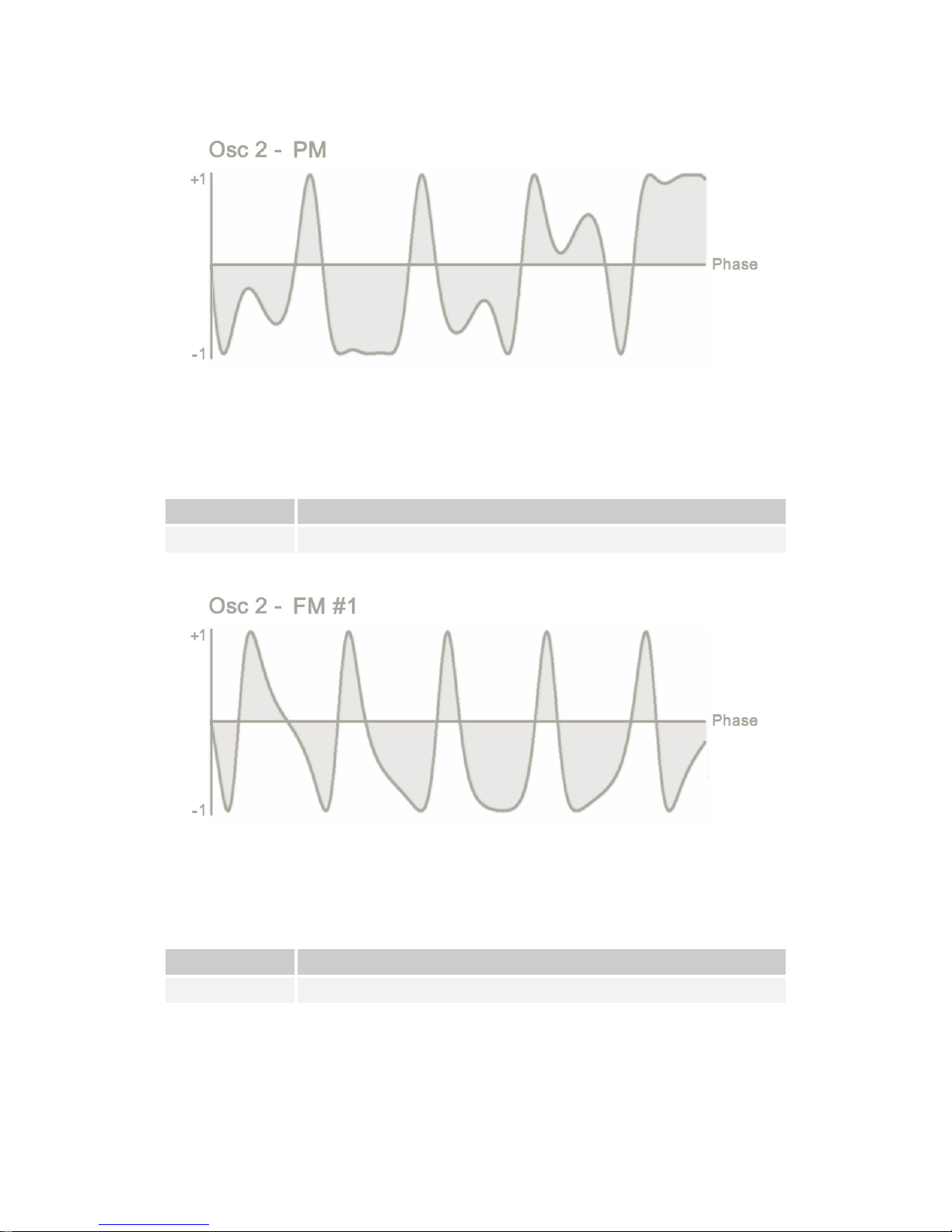
Phase Modulation (PM)
Phase modulation alters the output of Oscillator 2 by using the output of Oscillator 1 to alter
the phase of Oscillator 2. QUAD employs cross-phase modulation, which allows Oscillators 2
to alter the phase of Oscillator 1. This creates a more complex waveform.
Amt 1
Sets the modulation amount of oscillator 1 to oscillator 2
Amt 2
Sets the modulation amount of oscillator 2 to oscillator 1
Rob Papen QUAD 8
Below is an example of phase modulation:
Frequency Modulation 1 (FM1)
Frequency modulation alters the output of Oscillator 2 by using the output of Oscillator 1 to
alter the frequency of Oscillator 1. QUAD employs cross-frequency modulation, which allows
Oscillators 2 to alter the frequency of Oscillator 1. This creates a more complex waveform.
Amt 1
Sets the modulation amount of oscillator 1 to osc i llator 2
Amt 2
Sets the modulation amount of oscillator 2 to oscillator 1
Below is an example of frequency modulation:
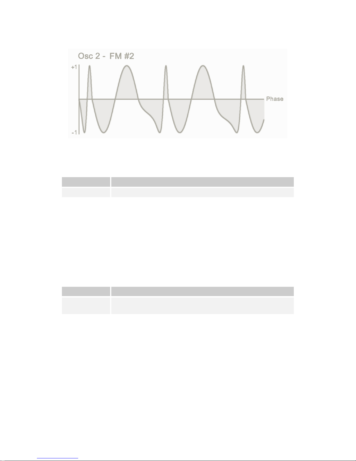
Frequency Modulation 2 (FM2)
FM2 is a non-pitched Sample & Hold modulation alg or it hm. Instead of the frequency
modulation by oscillator 1 being continuous, the amount of frequency modulation is updated
at set intervals. Oscillator 1 is sampled every interval and the sampled value is used to
modulate oscillator 2.
Amt 1
Sets the FM amount
Amt 2
Sets the Sample & Hold interval
Rob Papen QUAD 9
Here is an example of sample & hold FM
Frequency Modulation 3 (FM3)
FM2 is a tuned Sample & Hold modulation algorithm. It is similar to FM2 but the Sample &
Hold interval follows the pitch of Oscillator 2. Oscillator 1 is sampled every interval and the
sampled value is used to modulate oscillator 2.
Amt 1
Sets the FM amount
Amt 2
Sets the Sample & Hold interval
Frequency Modulation 4 (FM4)
FM4 uses alternating modulation amounts between the two oscillators. The modulation level
varies with every cycle. The modulation level in the first cycle of oscillator 2 is determined by
Amt 1 amount. The modulation level in the second cycle is set by Amt 2 amount. This pattern
repeats for all following odd and even waveform cycles.
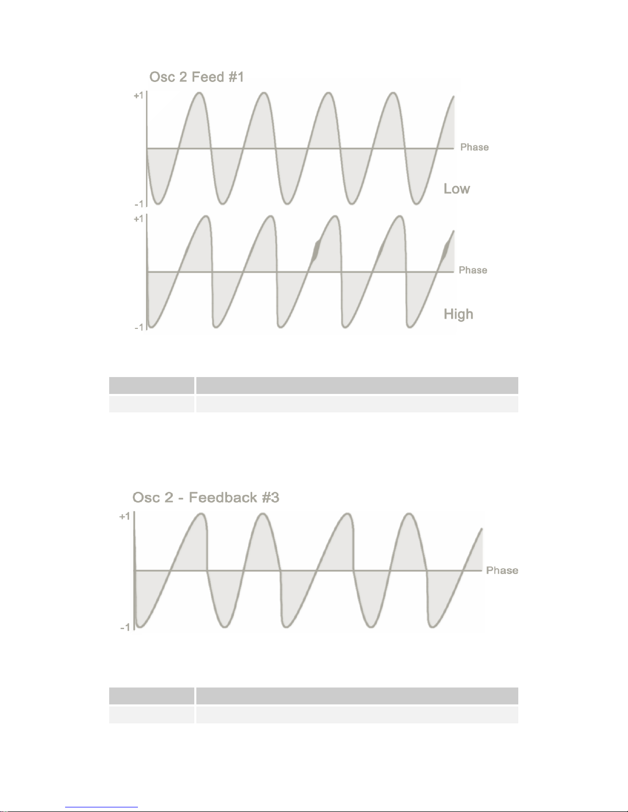
Feed 1
In the Feed 1 modulation function, Oscillator 2 modulates itself. It feeds back on itself in a
frequency modulation loop. At low modulation amounts, it would transform a sine wave
towards a saw wave. At high levels a chaotic waveform ensues.
Amt 1
Sets the modulation amount
Amt 2
Sets the balance between self-modulation and frequency modulation. (0
– self , 100% - FM)
Rob Papen QUAD 10
Feed 2
The Feed 2 modulation function is a delayed feedback modulation.
Amt 1
Sets the modulation amount
Amt 2
Sets the delay time
Feed 3
Feed 3 alternates the feedback level for Oscillator 2. The first cycle of Oscillator 2 is
modulated at Amt 1 amount, and second cycle is modulated at Amt 2 amount. This pattern
then repeats itself.
Sign
Sign uses the polarity of one oscillator to change the polarity of the other oscillator.
Amt 1
Sets the balance between the modulated signal and direct signal
Amt 2
Sets the direction of modulation between Oscillator 1 and Oscillator 2.
Rob Papen QUAD 11
The difference between sign of Osc 1 * absolute value of Osc 2, and sign of Osc 2 * absolute
value of Osc 1 can be seen here:
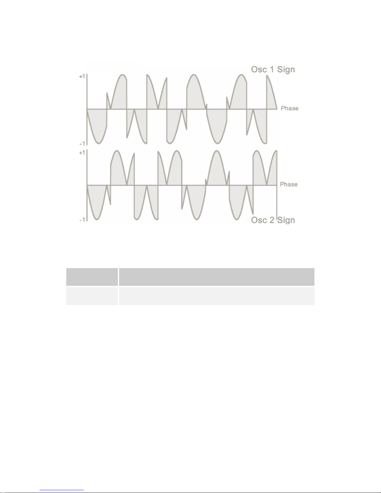
Min/Max
The Min/max function outputs a blend of the minimum and maximum values of oscillator 1
and 2
Amt 1
Sets the balance between the modulated signal and the direct signal of
oscillator 2
Amt 2
Sets the balance between the minimum of oscillators 1 and 2 and
maximum of oscillators 1 and 2.
Rob Papen QUAD 12
The following graph shows the difference between the minimum and maximum values:
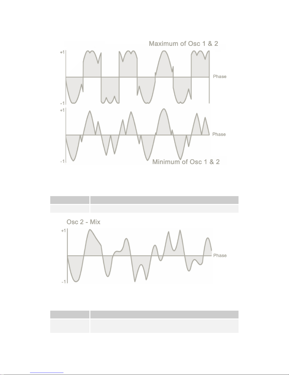
Mix
The Mix algorithm dynamically mixes the outputs from Oscillator 1 and Oscillator 2. It plays
oscillator 1’s output, followed by Oscillator 2’s output. The frequency with which it alternates is
determined by Amt 2.
Amt 1
Sets the Mix level of oscillator 1
Amt 2
Sets the frequency of alternating between Oscillator 1 and Oscillator 2
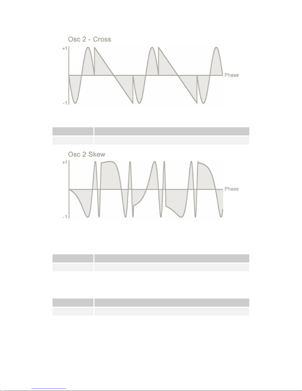
Cross
The cross modulation function plays a set number of cycles of oscillator 1, followed by a set
number of cycles of oscillator 2.
Amt 1
Determines the number of cycles to played from each oscillator
Amt 2
Sets the extent at which the oscillator pitch drives the number of cycles
played.
What follows is a display of a sine wave and a saw wave combined in the Cross algorithm:
Rob Papen QUAD 13
Skew
In Skew, the FM amount is controlled by the phase of oscillator 1.
Amt 1
Sets the FM amount for minimum phase of oscillator 1
Amt 2
Sets the FM amount for maximum phase of oscillator 1
Filter Modulation
In this modulation function, Oscillator 1 modulates the cutoff frequency of a low pass filter.
Oscillator 2 is fed through the filter. If you select a noise waveform for oscillator 1, the filter will
operate as a band pass filter.
Amt 1
Sets the centre frequency of low pass filter
Amt 2
Sets the resonance amount
String
String uses oscillator 2’s output in a string model (Karplus-Strong), to generate plucked
sounds.
Amt 1
Sets the length of string in the model
Amt 2
Sets the level of damping in the model
Rob Papen QUAD 14
Phase / Waveshape Distortion
The waveforms as generated by the oscillators are subject to further modulation through
Phase Distortion and Wave Shaping. You select these in the XY Pad section of QUAD as
explained in the next chapter. Each Phase Distortion and Wave Shaper type has two controls
to define the effect.
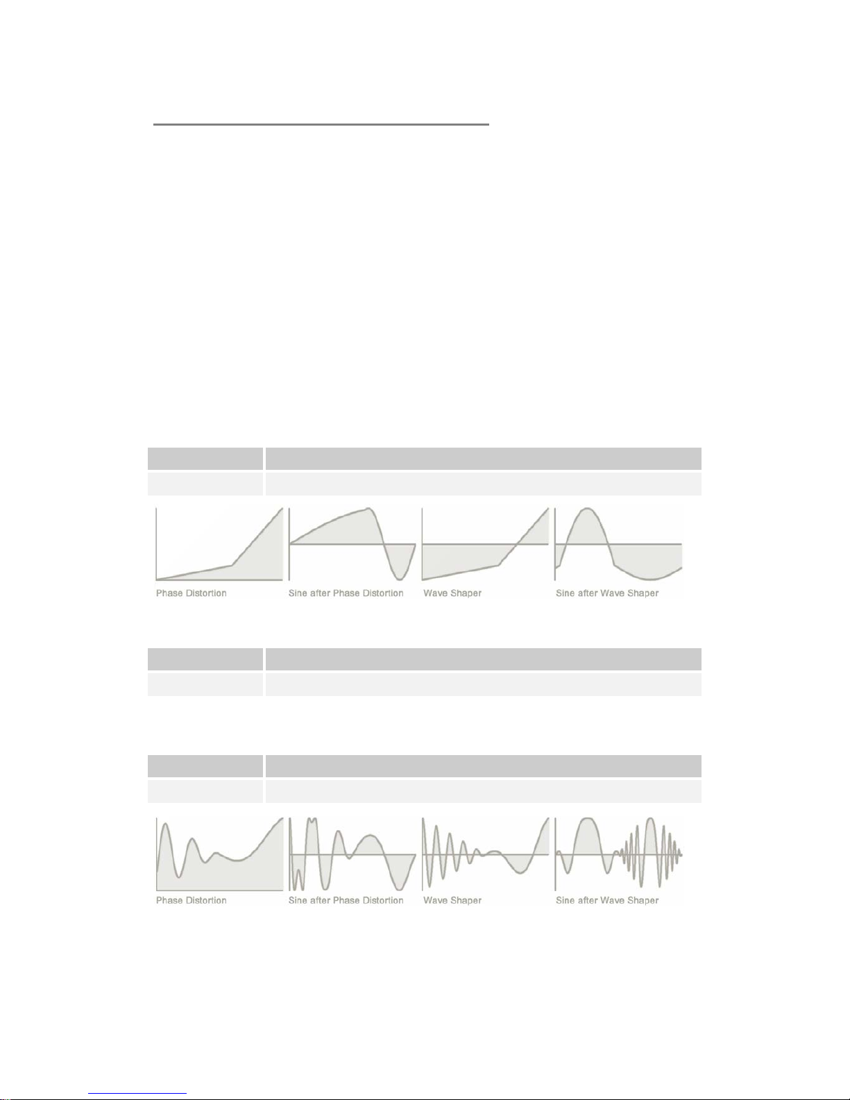
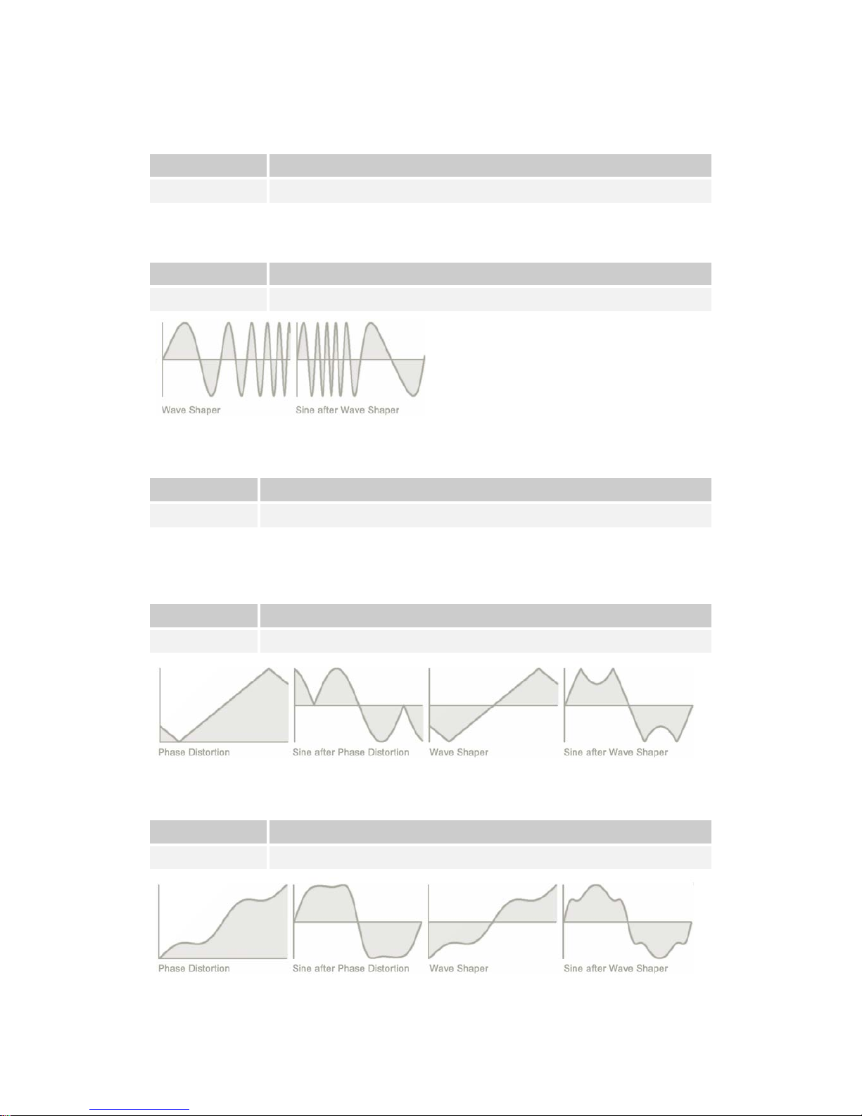
Distortion Types
The remainder of this chapter lists the various distortion and shaping algorithms and the
functions of the Amt 1 and Amt 2 controls. Where applicable the algorithms are illustrated by
a series of four wave form representations. In these illustrations:
• The first waveform is the Phase Distortion modulator
• The second waveform is the effect of the Phase Distortion on a sine wave
• The third waveform represents the Wave Shaper modulator
• The fourth waveform displays the effect of the Wave Shaper on a sine wave
2 Point
2 point applies phase distortion to the signal. Amt1 and Amt 2 control the mid-point position.
Amt 1
Sets the x coordinate of the mid-point.
Amt 2
Sets the x coordinate of the mid-point.
And
And applies a binary And-function to achieve bit reduction of the signal
Amt 1
Sets the multiplication factor of the And-function
Amt 2
Sets the mask value of the And-function
Cos1
Cos 1 uses a cosine function to modulate the input signal
Amt 1
Sets the frequency of the cos wave
Amt 2
Sets the symmetry level between positive and negative wave c ycles
Rob Papen QUAD 15
Cos2
Cos 2 uses a range of cosine frequencies as modulators. The Amt 1 and Amt 2 controls set
the width of the frequency window.
Amt 1
Sets the start frequency,
Amt 2
Sets the end frequency.
FM - Waveshaper only
FM applies classic frequency modulation to the signal
Amt 1 Sets the level of FM
Amt 2 Sets the frequency of the FM
Feed
Feed puts the signal in a (delayed) feedback loop which feeds the signal back onto itself.
Amt 1
Sets the delay of the feedback loop
Amt 2
Sets the feedback level.
Fold
Fold introduces distortion by amplifying the signal, clipping it, and subsequently folding over
the clipped sections of the waveform.
Amt 1
Sets the frequency of the fold-over distortion.
Amt 2
Sets the level of the fold-over distortion.
Fuzz
Fuzz is based on a classic fuzz pedal distortion.
Amt 1
Sets the frequency of the fuzz-distortion effec t
Amt 2
Sets the level of fuzz distortion
 Loading...