

Robot Coupe SM-50-EZ, SHFWEZ-1 Installation Manual
INSTALLATION
AND
OPERATING
R
INSTRUCTIONS
EASY-FILL HOT FOOD WARMER
Models:
SM50EZ, SHFWEZ-12D, SHFWEZ-1,
SHFWEZ-2D, -3D, -4D, -5D, -6D
WARNING: Improper installation, adjustment, alteration, service or maintenance can
cause property damage, injury or death. Read the Installation, Operating and
Maintenance Instructions thoroughly before installing or servicing this equipment.
Initial heating of unit may generate smoke or fumes and must be done in a well ventilated area.
Overexposure to smoke or fumes may cause nausea or dizziness.
This equipment has been engineered to provide you with year-round dependable service when used
according to the instructions in this manual and standard commercial kitchen practices.
Phone: +1 (214) 421-7366
Fax: +1 (214) 565-0976
Toll Free: +1 (800) 527-2100
Website: www.apwwyott.com
E-mail: info@apwwyott.com
UNIT MUST BE KEPT CLEAR OF COMBUSTIBLES AT ALL TIMES
INTENDED FOR OTHER THAN HOUSEHOLD USE
RETAIN THIS MANUAL FOR FUTURE REFERENCE
!!
P/N 70103009 3/08
APW WYOTT
729 Third Avenue
Dallas, TX 75226
1

TABLE OF CONTENTS
General Installation 2
Specifications: A SM50EZ 4
B SM50EZ-12D 5
C SHFWEZ-1D 6
D SHFWEZ-2, -3, -4, -5, -6 7
SM50EZ Parts List & Exploded View 8
Wiring Diagram 9
SHFWEZ-12D Parts List & Exploded View 10
Wiring Diagram 11
SHFWEZ-1D Parts List & Exploded View 12
Wiring Diagram 13
SHFWEZ-1D w/Shut-Off Valve Parts List & Exploded View 14
SHFWEZ-2, -3, -4, -5, -6 Parts List & Exploded View 16
SHFWEZ-2D, -3D, -4D, -5D, -6D w/Shut-Off Valve Parts List & Exploded View 18
Wiring Diagram 20
Warranty 22
GENERAL INSTALLATION
1. Always clean equipment thoroughly before use. (See general cleaning instructions.)
2. Check rating label for your model designation & electrical rating.
3. For best results, use stainless steel counter tops.
4. All dimensions in parenthesis in centimeters unless noted.
INSTALLATION INSTRUCTIONS FOR EZ WELL SUPPLY LINE
1. Install PIN 54508, brass fitting in each end of the solenoid using Teflon tape (not supplied).
2. Wrap the threads of the fitting as shown in the figure NO.1.
3. Remove the nut from the brass fitting and the sleeve from the inside of the fitting.
4. Place the sleeve and the nut, nut first, over the W copper tubing, PIN 54578, supplied with the
equipment.
5. Install the line into the solenoid and tighten the nut finger tight.
6. Using a wrench, tighten the nut far enough to crush the sleeve and attach the line.
NOTE: Do not over tighten nut. Just enough pressure is required to stop water leaks.
7. Install the 3/8 x 1/4 adapter to the 3/8 stainless steel tube fitting using Teflon tape as shown in
figure NO.2.
8. Using the other end of the copper tube, install the line, nut, and sleeve to the adapter.
9. Tighten using the same procedure as before.
10. Turn on water supply and look for leaks. If any leaks are found, tighten the nuts until leak is stopped.
NOTE: With EZ-fill multi-well units, turning on any of the controls will start water to fill all of the wells.
To fill, turn one control to the first position and allow all wells to fill completely. After wells are full, set
controls to desired settings.
INSTALLATION MUST BE DONE BY AUTHORIZED PLUMBER.
2
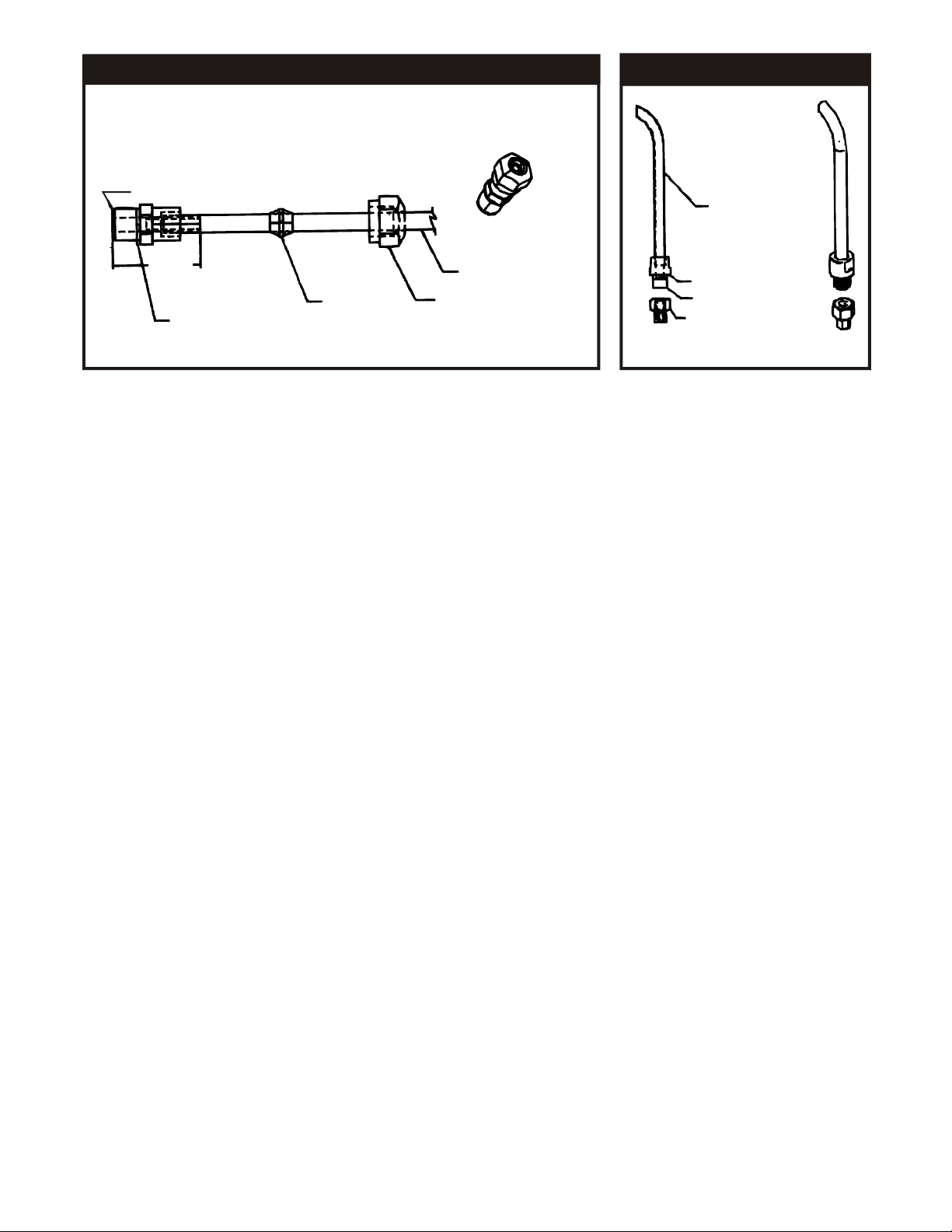
FIGURE #1
Part Description: Brass Connector Male 1/8” NPT x 1/8” Tube
1/8 NPT
FIGURE #2
Inlet Tube
1.125
Sleeve
Teflon Tape APW
#89117, as Required
1/4” Copper Tube
Fitting Nut
Coupling
Teflon Tape
3/8” Female to
1/4” Tube Adaptor
GENERAL OPERATION INSTRUCTIONS
1 . All food service equipment should be operated by trained personnel.
2. Do not allow your customers to come in contact with any surface labeled "CAUTION HOT."
3. Do not cook, warm or hold food directly in liner pans (well pans). Always use steam table pans /
insets, etc. Steam table pan depth should not exceed 6".
4. Never hold food below 150°F (66°C).
Wet set-up and operation procedures (Units with drains)
1. Turn thermostat control to "10" setting or if equipped with infinite controls to "7" or "HI". Preheat for
approximately 30 minutes. Pans will fill, to correct level, with water to white probe. . 2. Place covered
inset with preheated product into well. 3. Readjust control after another 30 minutes of operation to
the "6" setting depending on the amount and/or thickness of product. 4. Keep inset / steamtable
pan(s) covered to maintain ideal serving temperature. 5. Water is automatically kept at correct level.
NOTE: Turning on any control will activate autofill.
GENERAL CLEANING INSTRUCTIONS
1. NEVER clean any electrical unit by immersing it in water. Turn off before surface cleaning.
2. Always clean equipment thoroughly before first use. Clean unit daily. Except where noted on charts:
Use warm, soapy water. Mild cleansers & PLASTIC scouring pads may be used to remove bakedon food & water scale.
3. Turn off electrical units before cleaning or servicing. All service should be performed by an APW
authorized agency.
GENERAL TROUBLESHOOTING
Always Ask & Check:
1. Is the unit connected to a live power source?
2. Check the circuit breaker.
3. Is power switch on & pilot light glowing?
4. Check rating label. Are you operating unit on proper voltage?
If the above checks out, and you still have problems, call an APW authorized service agency.
3
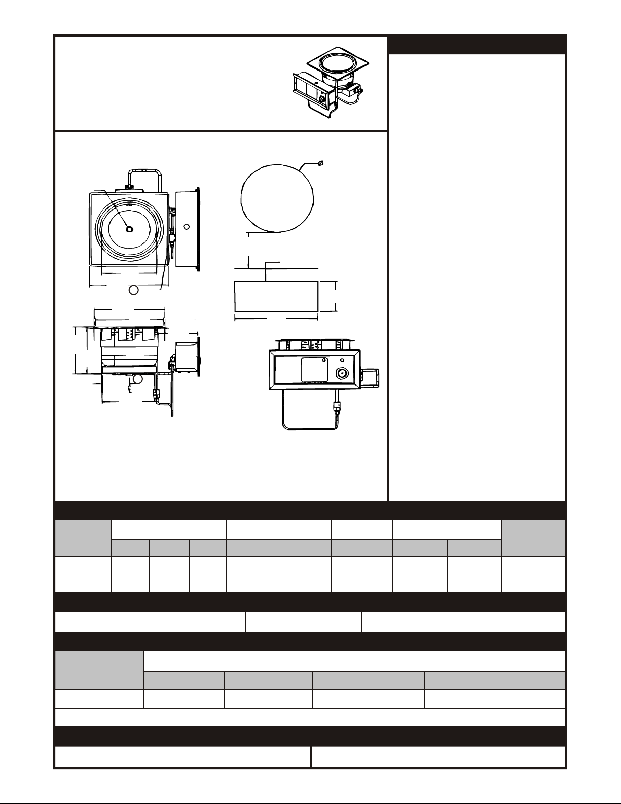
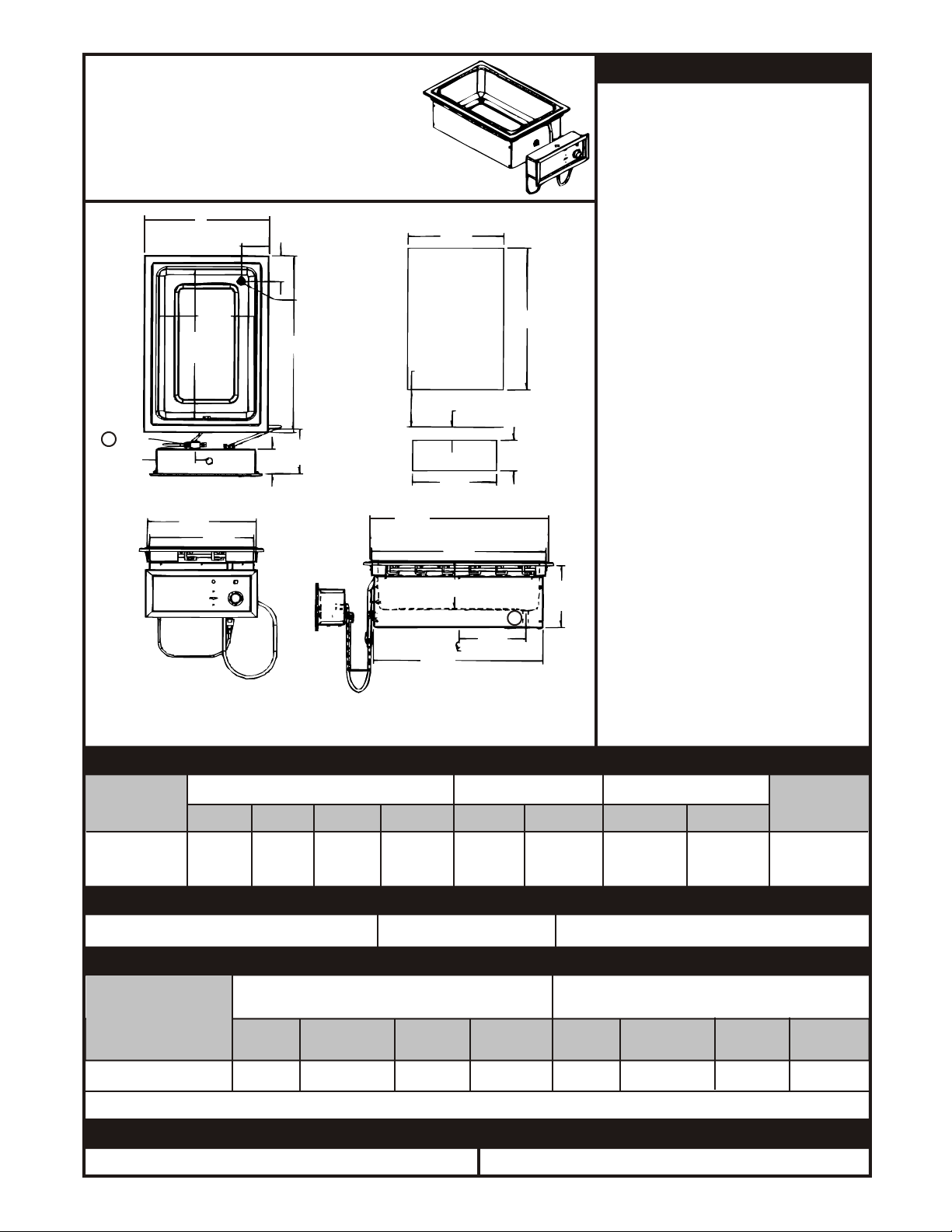
INSTALLATION
APW EZFILL HOT FOOD WELLS
Part Numbers Beginning with WHFW
D
Drain
6.0 (15.2) Minimum
From Counter Edge
E
7.78
(198)
12.02
(305)
7.55
(192)
4.19
(10.6)
10.69
(27.1)
C
1
B
8.12
(20.6)
Water
Inlet
A
610
(155)
2
1. Water fill is 3/8 (1.0) tubing connection on left back of left controls.
2. Main drain is ¾ female NPT.
Soup Well
Cut-out
2.0 (5.1) Minimum
From Counter Top
F
G
Control Cut-Out
1. Fo l l o w g en er al i ns ta ll at io n
instructions on page 3.
2. Make applicable Cut-Out per above
table. Note: Unit is designed for
installation in stainless steel tops.
Optional wood mounting kit available.
3. Apply putty tape to the underside
perimeter of the well rim outer edge.
4. Apply a 1/4" (.6) bead of silicone
sealant adjacent to the putty tape on
the well flange.
5. Drop well into opening from the top
and pus h d own unti l e ntire
parameter of rim is flush with the
counter surface.
6. From below the counter surface
insert an 8" to 10" (20 to 25 cm) flat tip
screwdriver into the locking ring tab
slots and twist in a clockwise motion
to lock well in place.
7. Trim excess putty and sealant from
around well rim.
8. Mount control to front panel using
hardware. Maintain 4" (10.2)
clearance between well and front
panel.
9. Check nameplate for proper voltage.
Connect power.
10. Connect overflow tube on hot food
well to suitable tubing to handle
212°F water. Run to open drain.
Note: Electrically connect units to
comply with local and NEC codes.
GENERAL SPECIFICATIONS (APW EZFILL HOT FOOD WELLS)
MODEL
OUTSIDE DIMENSIONS INSIDE DIMENSIONS
CUT-OUT CONTROL CUT-OUT
SHIP WT.
A B C E D F G
SM50EZ 10.34” 8.38” 6.44” 8.32” 10.875 5.0 12.5 13 Lbs.
WELL (26.3) (21.3) (16.4) (21.1) (27.6) (12.7) (31.8) (5.9 Kg)
OPTIONS
Description: Lever Operated Drain Valve Stock Number: 56360 Drain Manifold: Fabricated to Unit, Required
ELECTRICAL SPECIFICATIONS
ELECTRICAL RATINGS 500 EA. @ 208V / 660 EA. @ 240V
MODEL
VOLTS WATTS AMPS (1 Phase) MAX AMPS (3 PHASE)
SM50EZ WELL 208/240 500/660 2.4/2.75 N/A
NOTE: CUT-OUT SIZES ARE DIFFERENT FROM STANDARD APW HOT FOOD WELLS (HFW’S)
OPERATION
1. Follow General Operating Instructions on page 3. 1. Follow General Cleaning Instructions on page 3
CLEANING
4
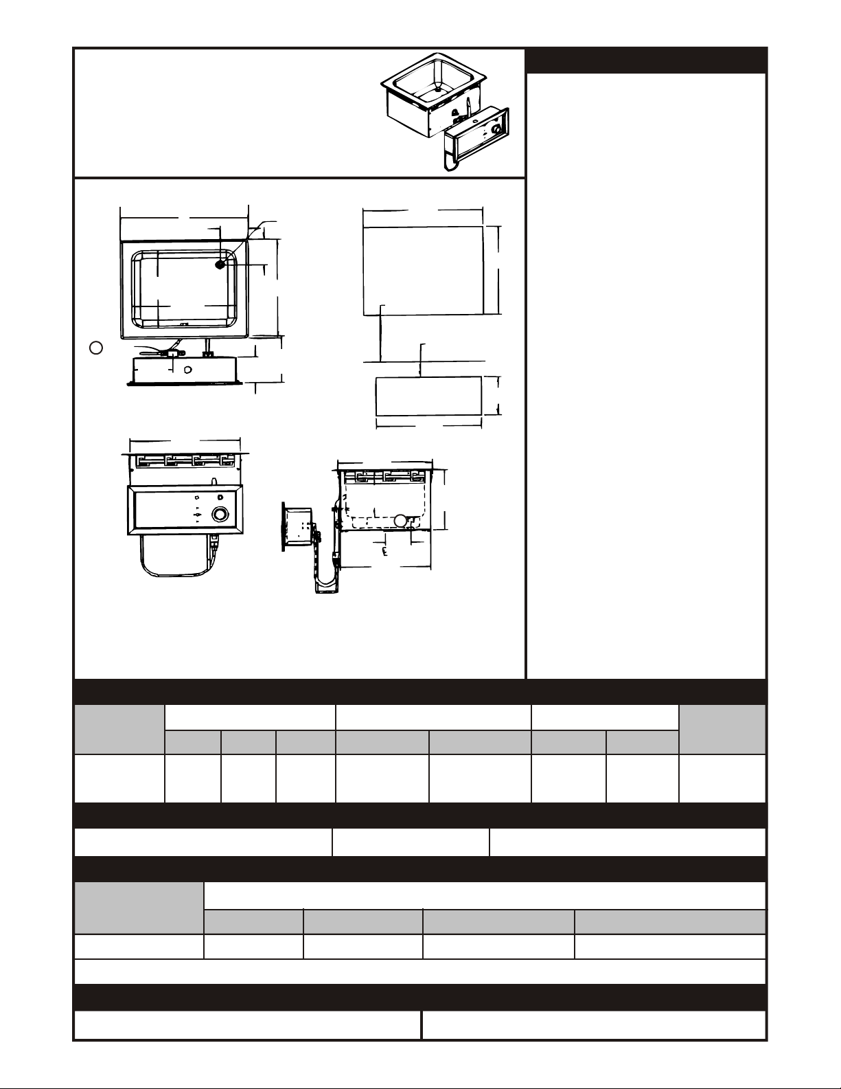
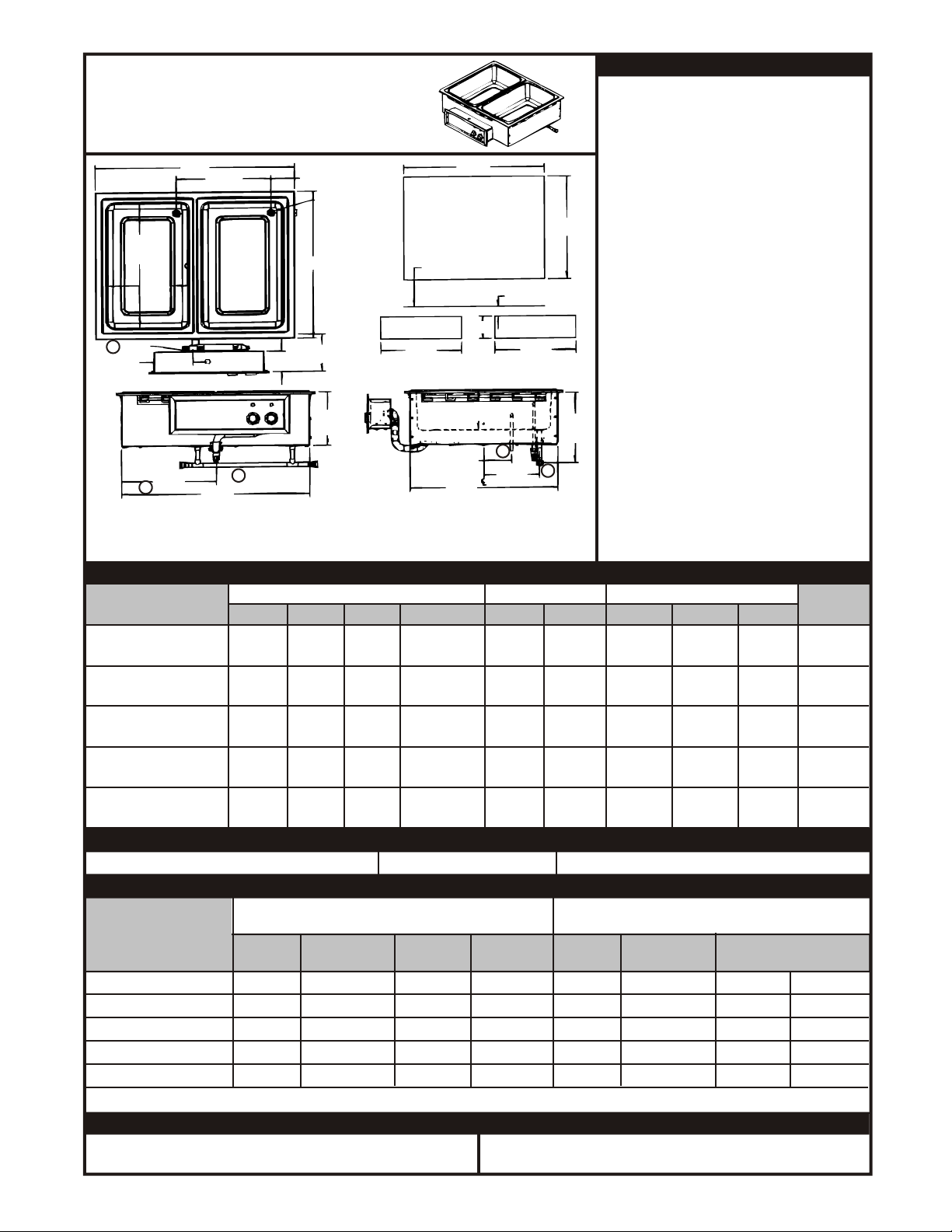
INSTALLATION
APW EZFILL HOT FOOD WELLS
Part Numbers Beginning with WHFW
3.29
3.29
(8.4)
3.28
(8.3)
(8.4)
Drain
B
Cut-Out
Front Edge
6.00
(15.2)
11.23
(28.5)
6.12
(15.6)
10.86
(27.6)
1
Water
Inlet
10.00
(25.4)
4.74
(12.0)
A
12.50
(31.8)
C
1. Water fill is 3/8 (1.0) tubing connection on left back of left controls.
2. Main drain is ¾ female NPT.
D
Hot Food Well
Cut-Out
6.00 (15.2) Minimum
From Counter Edge
2.00 (5.1) Minimum
From Counter Top
G
Control Cut-Out
7.72
(19.6)
2
3.07
(7.8)
1. Fo l l o w g en er al i ns ta ll at io n
instructions on page 3.
2. Make applicable Cut-Out per above
table. Note: Unit is designed for
installation in stainless steel tops.
Optional wood mounting kit available.
3. Apply putty tape to the underside
perimeter of the well rim outer edge.
4. Apply a 1/4" (.6) bead of silicone
sealant adjacent to the putty tape on
E
the well flange.
5. Drop well into opening from the top
and pus h d own unti l e ntire
parameter of rim is flush with the
counter surface.
6. From below the counter surface
insert an 8" to 10" (20 to 25 cm) flat tip
screwdriver into the locking ring tab
F
slots and twist in a clockwise motion
to lock well in place.
7. Trim excess putty and sealant from
around well rim.
8. Mount control to front panel using
hardware. Maintain 4" (10.2)
clearance between well and front
panel.
9. Check nameplate for proper voltage.
Connect power.
10. Connect overflow tube on hot food
well to suitable tubing to handle
212°F water. Run to open drain.
Note: Electrically connect units to
comply with local and NEC codes.
GENERAL SPECIFICATIONS (APW EZFILL HOT FOOD WELLS)
MODEL
OUTSIDE DIMENSIONS
CUT-OUT
CONTROL CUT-OUT
SHIP WT.
A B C E D F G
SM50EZ-12D 15.21 12.71 13.49 13.75 11.50 5.0 12.5 22 Lbs.
WELL (38.6) (32.3) (34.3) (34.9) (29.2) (12.7) (31.8) (10.6 Kg)
OPTIONS
Description: Lever Operated Drain Valve Stock Number: 56360 Drain Manifold: Fabricated to Unit, Required
ELECTRICAL SPECIFICATIONS
ELECTRICAL RATINGS 500 EA. @ 208V / 660 EA. @ 240V
MODEL
VOLTS WATTS AMPS (1 Phase) MAX AMPS (3 PHASE)
SM50EZ-12D WELL 208/240 500/660 2.4/2.75 N/A
NOTE: CUT-OUT SIZES ARE DIFFERENT FROM STANDARD APW HOT FOOD WELLS (HFW’S)
OPERATION
1. Follow General Operating Instructions on page 3. 1. Follow General Cleaning Instructions on page 3
CLEANING
5
INSTALLATION
APW EZFILL HOT FOOD WELLS
Part Numbers Beginning with WHFW
A
3.42
1
Water
Inlet
4.74
(12)
(8.7)
11.75
(29.8)
19.75
(50.2)
C
H
3.28
(8.3)
3.45
(8.8)
Drain
B
Cut-Out
Front Edge
6.00
(15.2)
21.80
(55.4)
1. Water fill is 3/8 (1.0) tubing connection on left back of left controls.
2. Main drain is ¾ female NPT.
D
Hot Food Well
Cut-Out
6.00 (15.2)
Minimum
From
Counter Edge
2.00 (5.1) Minimum
From Counter Top
G
Control Cut-Out
21.44
(54.4)
6.50 (16.5)
8.27
20.84
(52.9)
(21)
E
F
2
8.28
(21)
1. Fo l l o w g en er al i ns ta ll at io n
instructions on page 3.
2. Make applicable Cut-Out per above
table. Note: Unit is designed for
installation in stainless steel tops.
Optional wood mounting kit available.
3. Apply putty tape to the underside
perimeter of the well rim outer edge.
4. Apply a 1/4" (.6) bead of silicone
sealant adjacent to the putty tape on
the well flange.
5. Drop well into opening from the top
and pus h d own unti l e ntire
parameter of rim is flush with the
counter surface.
6. From below the counter surface
insert an 8" to 10" (20 to 25 cm) flat tip
screwdriver into the locking ring tab
slots and twist in a clockwise motion
to lock well in place.
7. Trim excess putty and sealant from
around well rim.
8. Mount control to front panel using
hardware. Maintain 4" (10.2)
clearance between well and front
panel.
9. Check nameplate for proper voltage.
Connect power.
10. Connect overflow tube on hot food
well to suitable tubing to handle
212°F water. Run to open drain.
Note: Electrically connect units to
comply with local and NEC codes.
GENERAL SPECIFICATIONS (APW EZFILL HOT FOOD WELLS)
MODEL
OUTSIDE DIMENSIONS
CUT-OUT CONTROL CUT-OUT
SHIP WT.
A B C H D E F G
SHFWEZ-1 15.38” 23.44” 13.80” 12.85” 14.25” 22.25” 5.0” 12.5” 12.4 Lbs.
WELL (39.1) (59.5) (35.10) (32.6) (36.2) (56.5) (12.7) (31.8) (10.9 Kg)
OPTIONS
Description: Lever Operated Drain Valve Stock Number: 56360 Drain Manifold: Fabricated to Unit, Required
ELECTRICAL SPECIFICATIONS
ELECTRICAL RATINGS
1200 EA. @ 208V / 1600 EA. @ 240V
ELECTRICAL RATINGS
1600 EA. @ 208V
MODEL
VOLTS WATTS AMPS AMPS VOLTS WATTS AMPS AMPS
(1 Ph) (3 Ph) (1 Ph) (3 Ph)
SHFWEZ-1 WELL 208/240 1200/1600 5.8 / 6.7 N/A 208 1600 7.7 N/A
NOTE: CUT-OUT SIZES ARE DIFFERENT FROM STANDARD APW HOT FOOD WELLS (HFW’S)
OPERATION
1. Follow General Operating Instructions on page 3. 1. Follow General Cleaning Instructions on page 3
CLEANING
6
INSTALLATION
APW EZFILL HOT FOOD WELLS
Part Numbers Beginning with WHFW
D
Hot Food Well
Cut-Out
6.0 (15.2) Minimum
From Counter Edge
F
Control Cut-Outs
6.50 (16.5)
4.13
(10.5)
21.88
(55.6)
2
8.27
(21.0)
2.0 (5.1) Minimum
From Counter Top
1
19.75
(50.2)
Water
Inlet
11.74
(29.8)
2
Overflow
5.74
(14.6)
J
A
13.981
(35.51)
C
Manifold
3
3.284
(8.34)
3.434
(8.72)
Drain
B
6.0
(15.2)
(22.0)
Cut-Out
Front Edge
8.65
G
1. Water fill is 3/8 (1.0) tubing connection on left back of left controls.
2. Overflow drain is 1/2” (1.3) OD tube outlet
3. Main drain is ¾ female NPT.
H
3
1. Follow general installation instructions
on page 3.
2. Make applicable Cut-Out per above table.
Note: Unit is designed for installa tionin
stainless steel tops. Optional wood
mounting kit available.
3. Apply putty tape to the underside
perimeter of the well rim outer edge.
4. Apply a 1/4" (.6) bead of silicone sealant
E
adjacent to the putty tape on the well
flange.
5. Drop well into opening from the top a n d
push down until entire parameter of rim
is flush with the counter surface.
6. From below the counter surface insert
an 8" to 10" (20 to 25 cm) flat tip
screwdriver into the locking ring tab slots
and twist in a clockwise motion to lock
well in place.
7. Trim excess putty and sealant from
around well rim.
8. Mount control to front panel using
11.27
(28.6)
hardware. Maintain 4" (10.2) clearance
between well and front panel.
9. Check nameplate for proper voltage.
Connect power.
10. Connect overflow tube on hot food well
to suitable tubing to handle 212°F water.
Run to open drain. Note: Electrically
connect units to comply with local and
NEC codes.
GENERAL SPECIFICATIONS (APW EZFILL HOT FOOD WELLS)
MODEL
OUTSIDE DIMENSIONS
A B C J Overflow D E F G H
CUT-OUT CONTROL CUT-OUT
SHIP WT.
SHFWEZ-2D WELL 29.42” 23.44” 27.79” 13.87” 28.5” 22.5” 5.0” 16.50” N/A 48 Lbs
(74.2) (59.5) (70.6) (35.2) (72.4) (57.2) (12.7) (41.9) (21.8 Kg)
SHFWEZ-3D WELL 43.46” 23.44” 41.83” 27.92” 42.5” 22.5” 5.0” 33.50” 68 Lbs
N/A
(110.4) (59.5) (106.2) (70.9) (108) (57.2) (12.7) (85.1) (30.8 Kg)
SHFWEZ-4D WELL 57.50” 23.44” 55.87” 27.92” 56.5” 22.5” 5.0” 16.50” 98 Lbs
12.50”
(146.0) (59.5) (141.9) (70.9) (143.5) (57.2) (12.7) (41.9) (44.4 Kg)
SHFWEZ-5D WELL 71.54” 23.44” 69.92” 41.96” 70.05” 22.5” 5.0” 33.50” N/A 118 Lbs
(181.7) (59.5) (177.6) (106.6) (179.1) (57.2) (12.7) (85.1) (53.5 Kg)
SHFWEZ-6D WELL 85.59” 23.44” 83.96” 41.96” 84.50” 22.5” 5.0” 33.50” N/A 260 Lbs
(217.4) (59.5) (213.2) (106.6) (214.6) (57.2) (12.7) (85.1) (117.9 Kg)
OPTIONS
Description: Lever Operated Drain Valve Stock Number: 56360 Drain Manifold: Fabricated to Unit, Required
ELECTRICAL SPECIFICATIONS
ELECTRICAL RATINGS
1600 EA. @ 208V
MODEL
ELECTRICAL RATINGS
1200 EA. @ 208V / 1600 EA. @ 240V
VOLTS WATTS AMPS AMPS VOLTS WATTS AMPS AMPS
(1 Ph) (3 Ph) (1 Ph) (3 Ph)
SHFWEZ-2D WELL 208/240 2400/3200 12 / 14 10 / 12 208 3200 16 14
SHFWEZ-3D WELL 208/240 3600/4800 18 / 20 10 / 12 208 4800 23 14
SHFWEZ-4D WELL 208/240 4800/6400 24 / 27 16 / 18 208 6400 31 21
SHFWEZ-5D WELL 208/240 6000/8000 29 / 34 20 / 24 208 8000 39 27
SHFWEZ-6D WELL 208/240 7200/9600 35 / 40 20 / 24 208 9600 47 27
NOTE: CUT-OUT SIZES ARE DIFFERENT FROM STANDARD APW HOT FOOD WELLS (HFW’S)
OPERATION
1. Follow General Operating Instructions on page 3. 1. Follow General Cleaning Instructions on page 3
CLEANING
7
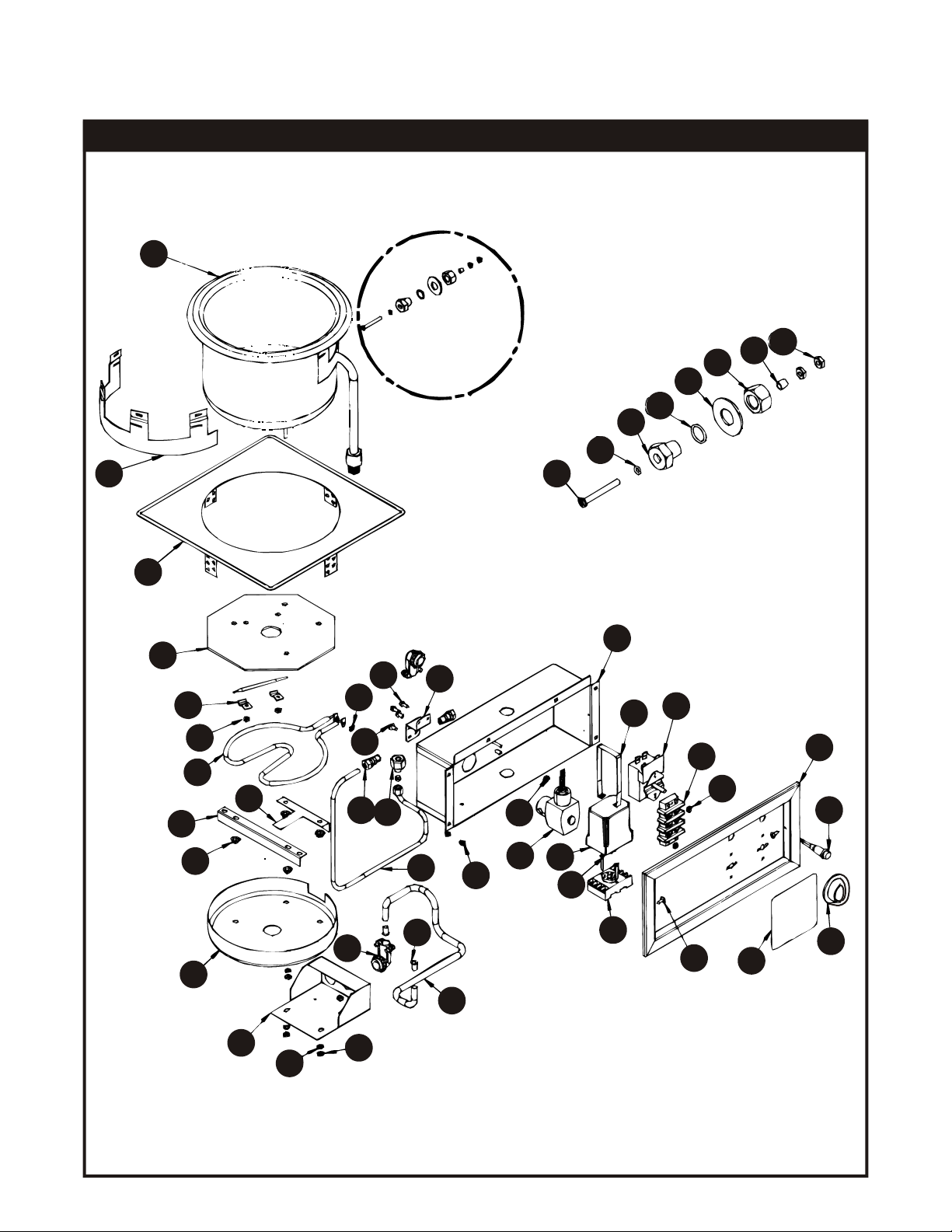
PARTS LIST & EXPLODED VIEW
SM50EZ Round Soup Well Drop-In with EZ Lock P/N EZSM50-7D 208/240V, 500/650W
EXPLODED VIEW SM50EZ
16
32
31
28
27
25
“B”
26
29
45
30
DETAIL “B”
44
17
20
41
22
24
18
21
19
8
23
36
15
37
1
10
13
3
14
2
35
6
7
40
35
34
11
12
43
9
42
33
5
4
39
38
23
24
8
 Loading...