

Page 1

Refrigerant Recovery Machine
Model No. RG6
Operating Manual
Bedienungsanleitung
Manual de operaciones
Manuel d’utilisation
1
Page 2

Safety PrecautionS
WARNING : TO PREVENT PERSONAL INJURY AND / OR EQUIPMENT DAMAGE,
ALLOW ONLY QUALIFIED PERSONNEL TO OPERATE THIS UNIT. Before operating the unit,
read and follow the instructions and warnings in this manual. The operator must be familiar with air
conditioning and refrigeration systems, refrigerants, and the dangers of pressurized components. If
the operator cannot read this manual, operating instructions and safety precautions must be read and
discussed in the operator’s native language.
PRESSURIZED TANK CONTAINS LIQUID REFRIGERANT. Do not overll storage vessels, because
overfilling may cause explosion and personal injury or death. Do not recover refrigerants into
nonrellable containers; use only federally authorized rellable containers (DOT spec. 4BW or 4BA).
HOSES MAY CONTAIN LIQUID REFRIGERANT UNDER PRESSURE. Contact with refrigerant may
cause personal injury. Wear protective equipment, including safety goggles and protective gloves.
Disconnect hoses using extreme caution.
AVOID BREATHING A/C REFRIGERANT AND LUBRICANT VAPOR OR MIST. Exposure may
irritate eyes, nose, and throat. To remove refrigerant from the A/C systen, use only equipment certied
for the type of refrigerant being removed. Use the unit in locations with mechanical ventilation that
provides at least four air changes per hour. If accidental system discharge occurs, ventilate the work
area before resuming service.
TO REDUCE THE RISK OF FIRE, USE THE SHORTEST POSSIBLE EXTENSION CORD WITH A
MINIMUM SIZE OF 14 AWG. Using an undersized extension cord may result in electrical equipment
failure.
TO REDUCE THE RISK OF FIRE, do not use the unit in the vicinity of spilled or open containers of
gasoline or other ammable substances.
CAUTION – DO NOT PRESSURE TEST OR LEAK TEST EQUIPMENT OR VEHICLE AIR
CONDITIONING SYSTEMS WITH COMPRESSED AIR. Some mixtures of air and refrigerant have
been shown to be combustible at elevated pressures. These mixtures, if ignited, may cause injury or
property damage.
DO NOT MIX REFRIGERANT TYPES THROUGH A SYSTEM OR IN THE SAME CONTAINER.
Mixing of refrigerants causes severe damage to the unit and the system being serviced.
HIGH VOLTAGE ELECTRICITY INSIDE THE UNIT HAS A RISK OF ELECTRICAL SHOCK. Exposure
may cause personal injury. Disconnect power before servicing the unit.
Additional health and safety information may be obtained from
refrigerant and lubricant manufacturers.
Explanation of SafEty Signal WordS
WARNING : Indicates a potentially hazardous situation which, if not avoided, could result in death or
serious injury.
CAUTION : Indicates a potentially hazardous situation which, if not avoided, may result in minor or
moderate injury.
CAUTION : Used without the safety alert symbol indicates a potentially hazardous situation which, if not
avoided, may result in property damage.
2
Page 3

table of contentS
Safety Precautions . . . . . . . . . . . . . . . . . . . . . . . . . . . . . . . . . .2
Explanation of Safety Signal Words . . . . . . . . . . . . . . . . . . . . . . . . .2
Understanding Refrigerant Recovery . . . . . . . . . . . . . . . . . . . . . . . .4
Standard Operating Instructions . . . . . . . . . . . . . . . . . . . . . . . . . . .5
Setup . . . . . . . . . . . . . . . . . . . . . . . . . . . . . . . . . . . . .5
Recovery Procedure . . . . . . . . . . . . . . . . . . . . . . . . . . . . .6
Purge the Unit. . . . . . . . . . . . . . . . . . . . . . . . . . . . . . . . .6
Operating Instructions for Bulk Liquid Systems . . . . . . . . . . . . . . . . . . . 7
Push – Pull Procedure . . . . . . . . . . . . . . . . . . . . . . . . . . . .7
Liquid Recovery. . . . . . . . . . . . . . . . . . . . . . . . . . . . . . . .7
Vapor Recovery . . . . . . . . . . . . . . . . . . . . . . . . . . . . . . . .8
Purge Non-Condensable Gas from a Storage Cylinder . . . . . . . . . . . . . . .8
Recovery Cylinder Information. . . . . . . . . . . . . . . . . . . . . . . . . . . .9
Troubleshooting . . . . . . . . . . . . . . . . . . . . . . . . . . . . . . . . . . 10
Replacement Parts. . . . . . . . . . . . . . . . . . . . . . . . . . . . . . . . . 11
Rebuild Kits and Accessories . . . . . . . . . . . . . . . . . . . . . . . . . . . 12
Maintenance . . . . . . . . . . . . . . . . . . . . . . . . . . . . . . . . . . . . 13
Installation of the Filter and Filter / Drier . . . . . . . . . . . . . . . . . . 13
Burned-out System . . . . . . . . . . . . . . . . . . . . . . . . . . . . . 13
Storage . . . . . . . . . . . . . . . . . . . . . . . . . . . . . . . . . . . 13
German. . . . . . . . . . . . . . . . . . . . . . . . . . . . . . . . . . . . . . .15
Spanish. . . . . . . . . . . . . . . . . . . . . . . . . . . . . . . . . . . . . . .29
French . . . . . . . . . . . . . . . . . . . . . . . . . . . . . . . . . . . . . . . 43
Warranty Statement . . . . . . . . . . . . . . . . . . . . . . . .Inside Back Cover
3
Page 4

underStanding refrigerant recovery
NOTE: Throughout this operating manual the term “unit”
is used when referring to all models of RG6 refrigerant
recovery machines.
Refrigerant recovery is the process of taking refrigerant
out of a system and storing it in a cylinder. The following
information is critical to achieving the best refrigerant
recovery results.
Refrigerant
Identify the refrigerant type and quantity in the system to
be serviced.
The unit is approved for use with the following category
III, IV, and V refrigerants (per ARI-740) :
R-12, R-22, R-134a, R-401a, R-401b,R-401c, R-402a,
R-402b, R-404a, R-406a, R-407a, R-407b, R-407c,
R-407d, R-408a, R-409a, R-410a, R-411a, R-411b,
R-412a, R-500, R-502, R-507 R-509
Filters and Filter / Driers
CAUTION : Filters prevent contamination from entering
the unit, which reduces the risk of damage to the unit
and the system being serviced.
The unit is shipped with a lter screen installed behind
the inlet tting. Robinair strongly recommends that a
clean lter screen be used for every service job. Failure
to use a lter screen will invalidate your warranty.
Robinair also strongly recommends using a lter / drier
(Part No. 100343; not provided) at the inlet tting. Each
in-line lter / drier must be labeled and used for only one
type of refrigerant.
Valves
WARNING : To prevent personal injury, open
service and cylinder valves SLOWLY to allow
rapid shut-off of gas flow if necessary. Once it is
determined there is no danger, the valves may be
opened fully.
Isolate large amounts of refrigerant and close valves
after use, so if a leak should develop anywhere in the
system, refrigerant will not escape to the atmosphere.
Storage Cylinders
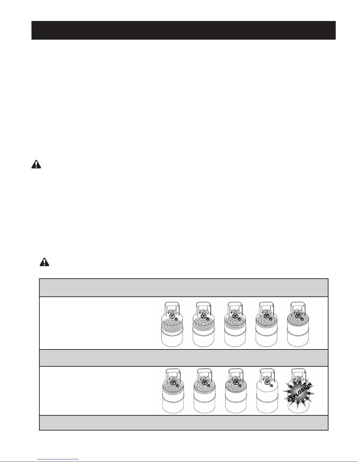
WARNING : A storage cylinder is full when it
reaches 80% volume. DO NOT OVERFILL. Due to
liquid expansion, the cylinder could explode if filled
to more than 80% volume, possibly causing personal
injury and equipment damage. Use a scale, such
as the TIF9010A, to avoid overfilling the storage
cylinder.
Robinair recommends using the optional 80% Capacity
Shutoff Kit (p/n SK-5001) with this unit. After the kit is
installed and used with a recovery cylinder having an
internal oat switch, the unit automatically shuts down
when the cylinder is 80% full. (Your unit is pre-wired at
the factory for this kit.)
Hoses
Hoses must be equipped with low-loss ttings and have
pressure ratings appropriate for the refrigerant in the
system being serviced.
Shut-off Switch
This unit has an internal, high-pressure, shut-off switch.
If system pressure rises above 550 psi, the unit shuts
off. The shut-off switch automatically resets itself after
pressure drops below 400 psi.
WARNING : The internal pressure shut-off
switch does NOT prevent cylinder overfill. If the
system shuts off automatically and is connected
to a cylinder, the cylinder may be dangerously
overfilled. Take immediate measures to relieve the
high pressure and / or cylinder overfill situation, or
personal injury may result.
Push / Pull Procedure
When recovering large amounts of liquid (over 15 lbs.),
use the Push / Pull method described in this manual.
Maximum Vacuum and Recovery Rates
To achieve the deepest nal vacuum, use an evacuated
recovery cylinder. To maximize recovery rates :
Use the shortest possible length of 3/8 in. or larger
•
hose. (A hose no longer than 3 feet is recommended.)
Remove unnecessary hose core depressors, and
•
remove Schrader valves from port connections.
Deformed rubber seals and core depressors in hoses,
as well as faulty or unnecessary Schrader valves, can
restrict ow.
If you are certain the refrigerant in the system being
•
serviced is clean or new, the lter screen may be
removed from the inlet tting.
Purge the unit during the end of the vapor recovery
•
phase, especially when recovering large amounts
of vapor. Purge again after the recovery process is
complete and the desired vacuum has been achieved.
Refer to “Purge the Unit” at the end of the Standard
Operating Instructions section of this operating
manual.
Maintenance
CAUTION :
system dry and clean. Damage will occur if moisture
is allowed to enter the system.
Keep all connections to the refrigeration
4
Page 5

Standard oPerating inStructionS
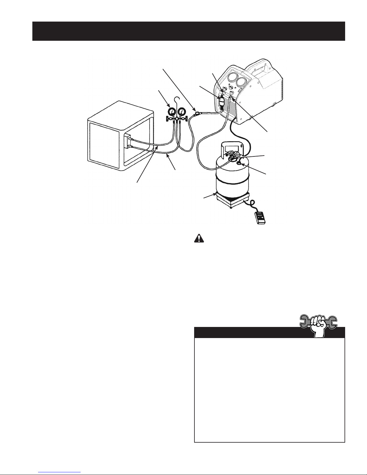
Sight
Glass
Manifold
Gauge Set
System Being
Serviced
Liquid
Vapor
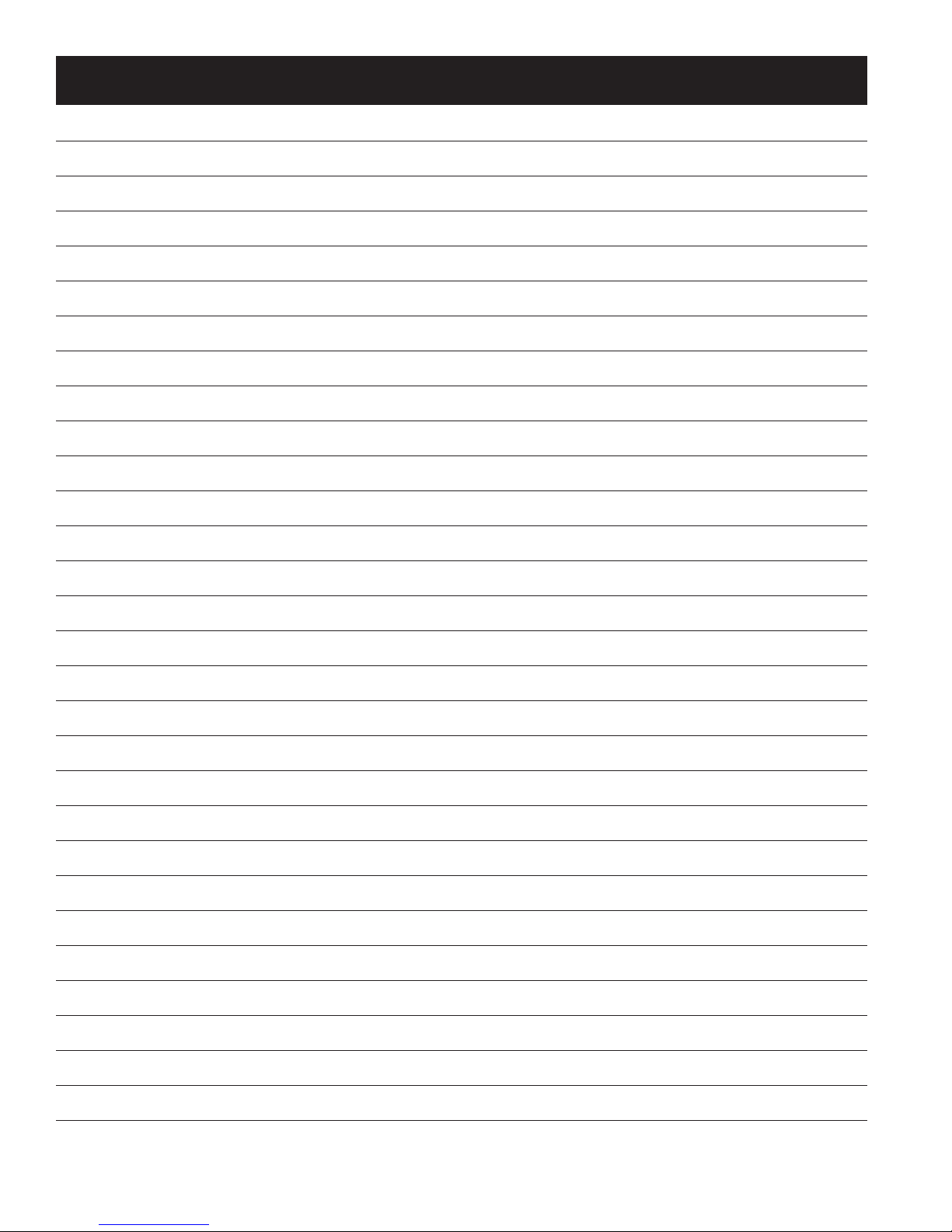
The following instructions are for a standard or
“common” recovery procedure.
Setup Procedure
1. Place the unit on a at, level surface.
2. Verify a clean lter screen is installed behind
the inlet tting.
Inlet
Fitting
Filter / Drier
Scale
WARNING : A storage cylinder is full when
it reaches 80% volume. DO NOT OVERFILL. Due
to liquid expansion, the cylinder could explode
if lled to more than 80% volume, possibly
causing personal injury and equipment damage.
Recovery
Cylinder
Outlet
Fitting
Liquid Port
Float Switch
Connection
(RG6 w/ SK-5001
kit installed)
3. Connect a hose from the outlet tting of the
unit to the liquid port on the recovery cylinder.
4. Connect a hose from the inlet tting of the unit
to the output port of a manifold gauge set.
Robinair recommends using a sight glass and
a lter / drier in this line.
5. Connect a hose from the liquid (low pressure)
side of the manifold gauge set to the liquid side
of the system being serviced.
6. Connect a hose from the vapor (high) side of
the manifold gauge set to the vapor side of the
system being serviced.
RG6 with SK-5001 kit installed: Attach tank
connection harness (No. 549977) to oat
switch connection on the recovery cylinder.
7. Verify the inlet and outlet valves on the unit are
closed.
8. Place the recovery cylinder on a scale (such as
TIF9010A) to avoid overlling the cylinder.
Tech Tips
The unit will perform at its peak when voltage
entering the machine (while operating) is between
115—122 VAC.
Lower supply voltages may result in difculty
starting under high head pressure, reduced
performance, and / or motor overheating.
Use an outlet that does not have other applicances
(such as lights, machines, etc.) plugged into it.
Do not use an extension cord unless needed. If
an extension cord is used, it must be 14 AWG
minimum and as short as possible to reduce
voltage drops.
5
Page 6

Standard oPerating inStructionS
Recovery Procedure
1. Connect the unit to an appropriate 115 V outlet.
2. Slowly open the liquid valve of the recovery
cylinder while watching hoses and connections for
leaks.
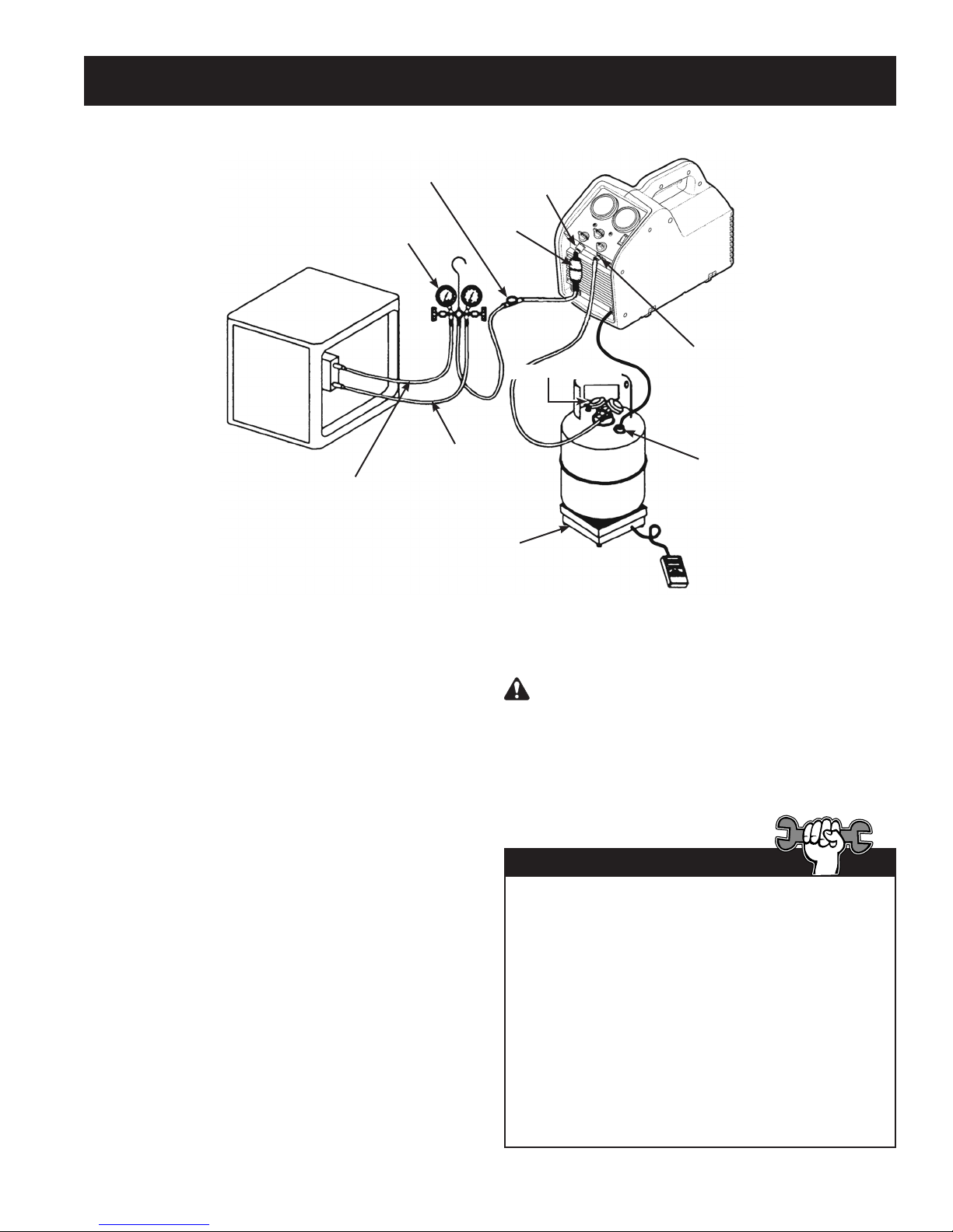
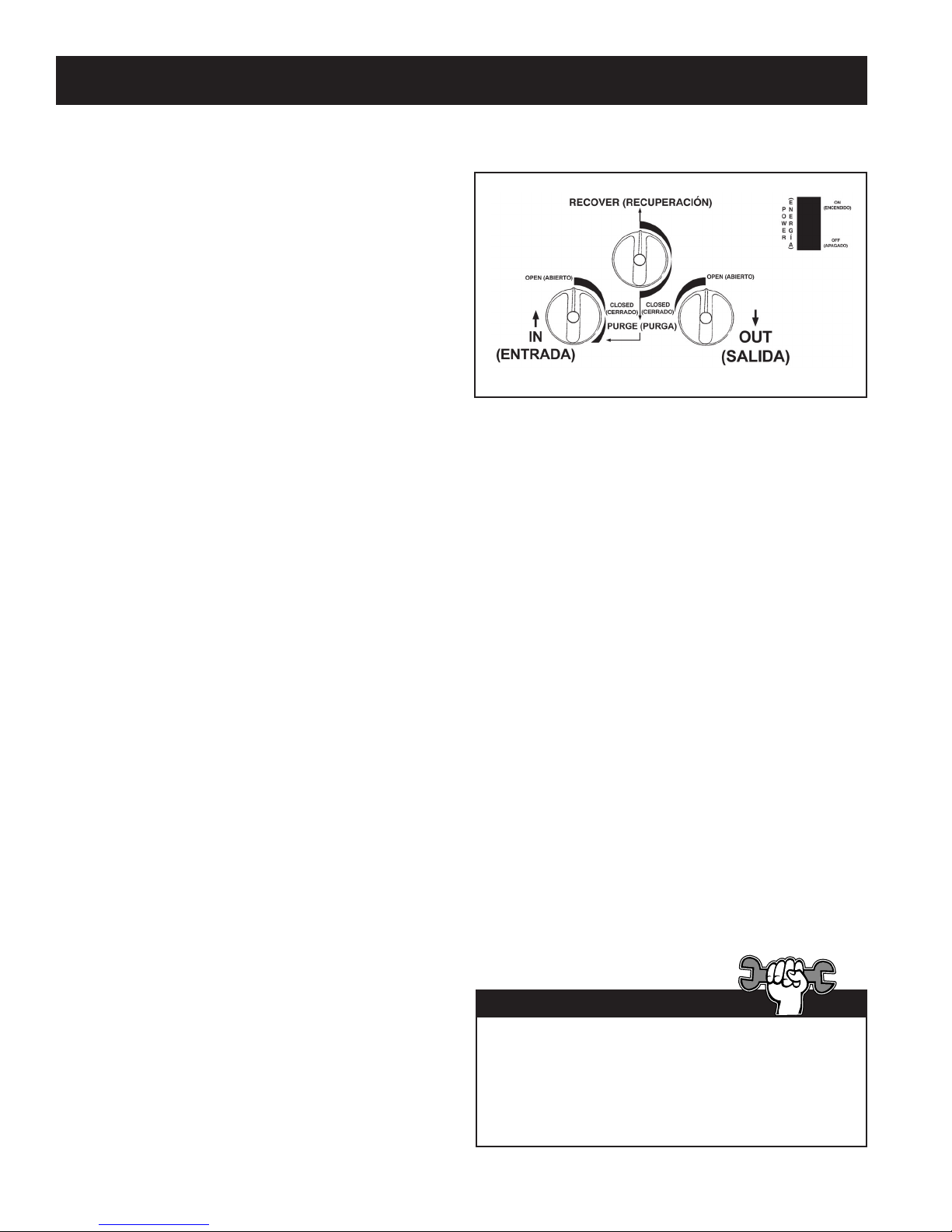
3. Set the recover / purge valve on the unit to
RECOVER.
4. Open the liquid valve on the manifold gauge set.
Note: Opening the liquid valve removes liquid from
the system rst, greatly reducing recovery time.
5. Open the outlet valve on the unit.
6. Toggle the power switch to the ON position.
7. Slowly open the inlet valve on the unit. Note: If the unit begins to “knock”, slowly throttle back (close)
the inlet valve until the noise stops.
8. Once the liquid has been removed from the system, open the vapor valve on the manifold gauge set to
nish evacuating the system.
9. Run the unit until the desired vacuum is achieved.
10. Close the vapor and liquid valves on the manifold gauge set.
11. Turn the inlet valve on the unit to the CLOSED position.
12. Toggle the power switch OFF.
Purge the Unit
CAUTION : Purge the unit after a recovery
procedure. Failure to purge the remaining
refrigerant from the unit could result in acidic
degradation of internal components, ultimately
causing premature failure of the unit.
1. Verify the liquid and vapor valves on manifold
gauge set are closed (if applicable).
2. Close the valves on the system being serviced
(if applicable).
3. Verify the outlet valve on the unit is open and
the inlet valve is closed.
4. Verify the liquid valve on the recovery cylinder
is open.
5. Turn the recover / purge valve to the PURGE
position.
6. Toggle the power switch ON.
7. Slowly turn the inlet valve toward the PURGE
position. As the inlet side pressure decreases,
open the valve to the full purge position.
8. Run the unit until the desired vacuum is
achieved.
9. Close the inlet and outlet valves on the unit.
10. Toggle the power switch OFF.
11. Close the ports on the recovery cylinder.
12. Turn the recover / purge valve to the
RECOVER position.
13. Disconnect all accessories and replace the inline lter.
If you have trouble starting or re-starting the unit
due to high head pressure, rst close the inlet
valve. Then slowly turn the inlet valve toward the
purge position until the inlet pressure rises. Close
the inlet valve again and re-start the unit.
6
Tech Tip
Page 7

oPerating inStructionS for bulk liquid SyStemS
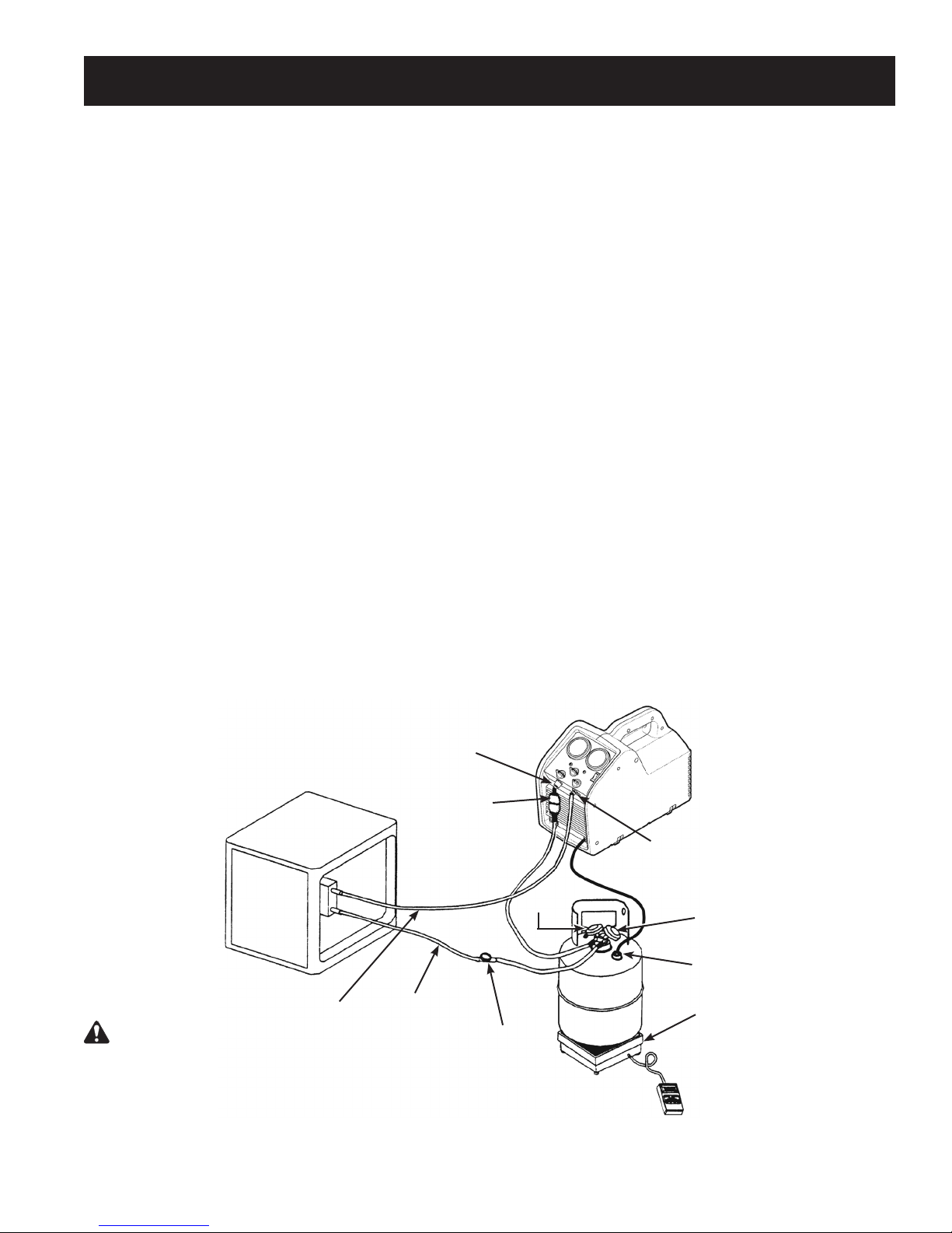
“Push – Pull” Procedure
The push – pull method removes bulk liquid from a system using the pressure differential created by the unit.
This method works only with large systems where the liquid is readily accessible; it may not work on systems
that contain less than 15 lbs. (6.8 kg) bulk liquid.
This method is used :
• on systems with receiver cylinders.
• on systems containing more than 20 lbs. (9.1 kg) of refrigerant.
• when transferring bulk liquid refrigerant from one cylinder to another.
Liquid Recovery
1. Place the unit on a at, level surface.
2. Connect a hose from the outlet tting of the unit
to the vapor port on the system being serviced.
3. Connect a hose from the inlet tting of the
unit to the vapor port of a recovery cylinder.
Robinair recommends using a lter / drier in
this line.
4. Connect a hose from the liquid side of the
recovery cylinder to the liquid port of the
system being serviced. Robinair recommends
using a sight glass in this line as a method of
determining when the liquid has been removed.
RG6 with SK-5001 kit installed: Attach tank
connection harness (No. 549977) to oat
switch connection on the recovery cylinder.
5. Place the recovery cylinder on a scale (such as
TIF9010A) to avoid overlling the cylinder.
Filter/Drier
System Being
Serviced
6. Verify inlet and outlet valves on unit are closed.
7. Turn the recover / purge knob to RECOVER.
8. Open the recovery cylinder valves.
9. Open the outlet valve on the unit.
10. Toggle the power switch ON.
11. SLOWLY open the inlet valve on the unit.
12. When the weight reading on the scale stops
increasing, close the inlet valve on the unit
rst; then close the liquid valve on the recovery
cylinder.
13. Toggle the power switch OFF.
14. Close the valves on the recovery cylinder, and
close the outlet valve on the unit.
15. Proceed to Vapor Recovery.
Inlet
Fitting
Outlet Fitting
WARNING : Manually close the valves on both the
storage cylinder and the unit to prevent overfilling the
cylinder. Once the siphon is started, it can overfill the
storage cylinder, even if the cylinder is equipped with a
float level sensor. The siphon can continue even when
the unit is turned off.
Vapor
Liquid
7
Sight
Glass
Scale
Vapor
Recovery
Cylinder
Liquid
Float Switch
Connection
(RG6 w/ SK-5001
kit installed)
Page 8

oPerating inStructionS for bulk liquid SyStemS
Vapor Recovery
1. Place the unit on a at, level surface.
2. Connect a hose from the inlet side of the unit to
the liquid port of the system being serviced.
Tech Tip
3. Connect a hose from the outlet side of the unit
to the liquid port on a recovery cylinder.
CAUTION: The recovery cylinder should be
on a scale to avoid overlling the cylinder.
4. Open the liquid valve on the recovery cylinder.
5. Turn the recover / purge knob to RECOVER.
6. Open the outlet valve on the unit.
7. Toggle the power switch ON.
8. Slowly open the inlet valve on the unit.
9. Run the unit until the desired vacuum is
achieved.
10. Close the inlet and outlet valves on the unit.
11. Toggle the power switch OFF.
12. Close the ports on the recovery cylinder.
For a faster recovery procedure, recover from both
the liquid and vapor ports of the system being
serviced by using a tee tting or manifold gauge
set in the hose setup.
Purge non-condenSable gaS from a Storage cylinder
1. Allow the storage cylinder to sit undisturbed for
24 hours to allow air to rise to the top.
2. Connect a manifold gauge set to the cylinder.
Read the amount of pressure in the cylinder as
indicated by the output pressure gauge.
3. Determine the ambient temperature in the
room.
4. Refer to a refrigerant pressure/temperature
chart and nd the ambient temperature. Read
across the chart to the corresponding pressure
for the type of refrigerant in the cylinder.
Determine how that relates to the reading on
the gauge.
5. If the pressure reading in the cylinder is
higher than the pressure shown on the chart,
VERY SLOWLY crack open the vapor port
valve. (This is done slowly to cause as little
turbulence inside the cylinder as possible.)
Watch the pressure on the gauge decrease. To
prevent venting, add 4–5 psi (0.26—0.34 bar)
to the pressure shown on the chart.When the
gauge corresponds to that pressure, close the
vapor port valve.
6. Allow the cylinder to sit for 10 minutes and then
check pressure again.
7. Repeat the process, if necessary.
8
Page 9

recovery cylinder information
Type of Cylinder
Use only authorized, rellable, refrigerant storage
cylinders. Federal regulations require refrigerant
to be transported only in containers meeting DOT
specs. 4BW or 4BA.
NEVER use a standard disposable 30 lb.
(13.6 kg) cylinder (the type of container in which
new refrigerant is sold) to recover refrigerant.
Working Pressure
Recovery cylinders are designed for different
working pressures. Robinair strongly recommends
the use of 400 psi (27.6 bar) cylinders.
WARNING: To prevent personal injury, do
not exceed the rated working pressure of the
cylinder. At minimum, the RG6 requires the use
of a 350 psi (24.1 bar) recovery cylinder.
NOTE: The use of a 400 psi (27.6 bar) cylinder is
mandatory when recovering R-410A refrigerant.
Refer to the Parts and Accessories section of this
manual for more information.
If you expect temperatures in excess of 135º F
(57° C), consult the refrigerant supplier.
Capacity
Safety codes state that closed cylinders should
not be lled with liquid over 80% of volume. (The
remaining 20% is called head pressure room.)
Do not exceed 80% of cylinder capacity. Robinair
recommends the use of the TIF9010A Refrigerant
Scale for monitoring cylinder capacity.
Refrigerants
Cylinders and lter / driers should each be
designated for only one type of refrigerant.
If you must use a cylinder previously used for
a different refrigerant, prepare the cylinder by
completely emptying it, perform an evacuation,
purge it using dry nitrogen, and then perform
another evacuation.
Storage
Store refrigerant cylinders in a cool, dry place.
Leakage
Some cylinders have valves that were not correctly
seated when manufactured. Keeping caps on the
valves will guard against refrigerant leakage.
WARNING : To prevent personal injury, never transport an overfilled cylinder.
Refrigerant expands when it gets warm and may cause an overfilled cylinder to explode.
Storage Cylinder Temperature 60°F 70°F 100°F 130°F 150°F
15.6°C 21.1°C 37.8°C 54.4°C 65.6°C
STARTING WITH CYLINDER
80% BY VOLUME
Space Occupied by Liquid 80% 81% 83% 90% 94%
STARTING WITH CYLINDER
90% BY VOLUME
Space Occupied by Liquid 90% 92% 96% 100%
9
Page 10

troubleShooting
WARNING: TO PREVENT PERSONAL INJURY AND / OR EQUIPMENT DAMAGE,
ALLOW ONLY QUALIFIED PERSONNEL TO OPERATE AND REPAIR THIS UNIT. Before operating
or repairing the unit, read and follow the instructions and warnings in this manual. The technician must
be familiar with air conditioning and refrigeration systems, refrigerants, and the dangers of pressurized
components. If the technician cannot read this manual, operating instructions and safety precautions
must be read and discussed in the technician’s native language.
Symptom Possible Cause Possible Solution
Unit will not turn on 1. Power cord not plugged in.
2. Bad power outlet.
3. Unit is in high-pressure shut-off.
4. Motor is in thermal overload.
5. Circuit breaker tripped.
Compressor tries to
start, but just buzzes
Unit pumps into highpressure shut-off
Slow recovery 1. Trapped liquid in system.
Circuit breaker trips 1. Low voltage at power source.
1. Low voltage at power source.
2. Extension cord too long, or too
small.
3. Head pressure too high.
1. Output valve on unit is closed.
2. Recovery cylinder valve closed.
3. Head pressure too high.
2. Restriction in refrigerant ow path.
2. Extension cord too long, or too
small.
3. Excessive load on compressor /
motor.
1. Check power cord at wall and unit.
2. Try a different outlet.
3. Reduce head pressure to below
400 psi (27.6 bar).
4. Allow motor / unit to cool down.
5. Check / reset circuit breaker.
1. Locate / use better outlet.
2. Reduce length of extension cord.
Increase size (gauge) of extension
cord (14 AWG minimum).
3. Reduce head pressure. Turn inlet
valve slightly past closed toward
PURGE to equalize high-side / low side pressure.
1. Check output valve.
2. Check recovery cylinder valve.
3. Check output hoses for restrictions
or kinks. Reduce head pressure.
1. Momentarily cycle system compressor
to move trapped refrigerant.
2. Check inlet hose for restrictions or
kinks. Remove Schrader valves and
core depressers from hoses (if
possible). Use larger hoses.
1. Locate / use better outlet.
2. Reduce length of extension cord.
Increase size (gauge) of extension
cord (14 AWG minimum).
3. Reduce head pressure. Throttle inlet
valve to reduce load on compressor.
10
Page 11

13
14
15
rePlacement PartS
1 (left side shown)
2
Motor Relay
& Capacitor
16
17
18
}
6
7
Divider
3
4
Motor Interface
5
Counterbalance
11
10
12
9
Item Part
No. No. Qty. Description
1 567913 1 Case Half (left)
567915 1 Case Half (right)
2 550503 1 Grommet (1 ea.)
3 SK-6013 1 Motor Clamp Kit (4 pieces)
4 SK-6005 1 Motor Kit (includes motor, relay,
capacitor, hardware)
5 SK-6023 1 Compressor Kit (includes
compressor, hardware)
6 SK-6008 1 Fan Kit (includes fan, spacer
mounting hardware)
7 GA1000 1 Gauge Lens (1 ea.)
8 100124 1 Manifold Knob (red)
9 100123 1 Manifold Knob (blue)
10 100122 1 Manifold Knob (black)
11 SK-6014 1 Condenser Kit (includes condenser
assembly, hardware)
Inlet / Outlet
Tubes
8
Item Part
No. No. Qty. Description
12 551628 1 Power Cord
13 SK-6012 1 Bezel Kit (includes bezel, power
switch, circuit breaker, power entry
module, hardware)
14 SK-6001 1 Inlet Fitting / Filter Screen Kit
(includes inlet tting, lter screen,
o-ring)
15 550502 1 Foot (1 ea.)
16 SK-6003 1 Low-side Gauge Kit (includes
low-side gauge, lens)
17 SK-6022 1 High-side Gauge Kit (includes
high-side gauge, lens)
18 SK-6016 1 Manifold Kit (includes manifold
assembly, hardware)
11
Page 12

rebuild kitS and acceSSorieS
Part
No. Description
SK-5001 80% Tank Shut-off Kit
SK-6001 Filter Screen Replacement Kit
SK-6002 Filter / Drier Kit (includes lter / drier, 6 inch hose)
SK-6005 Motor Replacement Kit
SK-6007 Valve Rebuild / Replacement Kit (includes inlet /oulet valves and springs, o-rings)
SK-6008 Fan Replacement Kit
SK-6012 Bezel Replacement Kit
SK-6014 Condenser Replacement Kit
SK-6015 Piston Seal Rebuild Kit (includes piston seals, energizer o-ring, wear bands)
SK-6016 Manifold Replacement Kit
SK-6023 Compressor Replacement Kit
SK-6022 Gauge Replacement Kit
TIF9010A Refrigerant Scale
17572 Recover Cylinder (50 lb. capacity, 400 psi working pressure, capacity sensor)
SK-6013 Motor Clamp Kit (4 pieces)
12
Page 13

maintenance
CAUTION : To prevent personal injury, disconnect the unit from the power supply before
performing maintenance.
Installation of the Filter and Filter / Drier
1. Before performing a refrigerant recovery, always inspect and clean the filter screen in the inlet fitting
on the unit. Replace the filter screen (p/n SK-6001) if necessary. A filter screen greatly reduces the
risk of damage to the unit by preventing foreign material from entering the unit and the system being
serviced. Failure to use a filter screen will invalidate the warranty.
Robinair also strongly recommends using an in-line filter / drier (p/n 100343) in the inlet line.
Filter
Screen
Inlet
Fitting
Filter /Drier
p/n 100343
Burned-out System
1. Use two high-acid capacity lter / driers in series when recovering from a “burned-out” system. Robinair
recommends Alco type EK-162-F or Sporlan type C-162-F lters.
When you have nished recovering from the system, ush the unit with a small amount of clean
refrigerant and refrigerant oil to purge any foreign substances left in the unit.
Storage
1. Empty refrigerant from the unit into a storage cylinder. Liquid refrigerant left in the unit’s condenser may
expand, causing damage to components.
2. Completely evacuate the unit of any residual refrigerant and purge it with dry nitrogen before putting it
in storage for a long period of time.
13
Page 14
14
Page 15

Kältemittel-Absauggerät
Model No. RG6
Bedienungsanleitung
15
Page 16

Vorsichtsmassnahmen
WARNUNG: UM VERLETZUNGEN UND/ODER GERÄTESCHÄDEN ZU VERMEIDEN,
LASSEN SIE DIESES GERÄT NUR VON QUALIFIZIERTEM PERSONAL BEDIENEN. Vor
Inbetriebnahme des Geräts lesen und befolgen Sie die Anweisungen und Warnhinweise in dieser
Bedienungsanleitung. Der Bediener muss mit Klimaanlagen und Kältesystemen, Kältemitteln und der
Gefahr von unter Druck stehenden Komponenten vertraut sein. Falls der Bediener dieses Handbuch
nicht lesen kann, müssen Bedienungsanweisungen und Vorsichtsmaßnahmen dem Bediener in seiner
Sprache vorgelesen und erklärt werden.
UNTER DRUCK STEHENDER BEHÄLTER ENTHÄLT FLÜSSIGES KÄLTEMITTEL. Die
Kältemittelbehälter dürfen keinesfalls überfüllt werden. Andernfalls können die Flaschen explodieren
und schwere oder tödliche Verletzungen verursachen. Verwenden Sie keine Einwegaschen zum
Absaugen von Kältemitteln. Verwenden Sie ausschließlich vom US-Verkehrsministerium zugelass-
ene, nachfüllbare Behälter (DOT Spezikation 4BW oder 4BA).
SCHLÄUCHE ENTHALTEN UNTER UMSTÄNDEN UNTER DRUCK STEHENDES FLÜSSIGES
KÄLTEMITTEL ENTHALTEN. Kontakt mit Kältemittel kann Verletzungen verursachen. Tragen Sie
stets Schutzausrüstung, einschließlich Schutzbrille und Schutzhandschuhe. Gehen Sie beim Abklemmen der Schläuche äußerst vorsichtig vor.
ATMEN SIE KEINE KÄLTE- UND SCHMIERMITTELGASE ODER DÄMPFE EIN. Kontakt mit Kälte- oder
Schmiermitteldämpfen oder -gasen kann Verletzungen, insbesondere an Augen, Nase, Hals und
Lunge, verursachen. Verwenden Sie das Gerät nur an Standorten mit mechanischer Belüftung, an
denen die Luft mindestens vier Mal stündlich ausgetauscht wird. Falls das System versehentlich
ausläuft, müssen Sie den Arbeitsbereich lüften, bevor Sie das Gerät wieder einschalten.
VERWENDEN SIE NUR EIN MÖGLICHST KURZES VERLÄNGERUNGSKABEL MIT EINER
KABELSTÄRKE VON MINDESTENS 14 AWG. Die Verwendung eines zu dünnen Verlängerungska-
bels kann zu einem Ausfall von Elektrogeräten führen.
UM DAS BRANDRISIKO SO GERING WIE MÖGLICH ZU HALTEN, verwenden Sie das Gerät nicht
in der Nähe von verschüttetem Benzin oder offenen Benzinkanistern oder anderen entzündlichen
Stoffen.
VERWENDEN SIE KEINE DRUCKLUFT, UM EINE DRUCK- ODER DICHTIGKEITSPRÜFUNG DES
GERÄTS ODER DER KLIMAANLAGE DURCHZUFÜHREN. Einige R-134a Kältemittel- und Luftgemische
sind bei erhöhtem Druck brennbar. Diese Gemische sind möglicherweise gefährlich und können einen
Brand oder eine Explosion und somit Verletzungen oder Sachschäden verursachen.
MISCHEN SIE NIEMALS VERSCHIEDENE KÄLTEMITTELTYPEN IN EINEM SYSTEM ODER IM
SELBEN BEHÄLTER. Durch Mischen verschiedener Kältemittel entstehen schwere Schäden am
Gerät sowie am System, das entleert wird.
HOCHSPANNUNG IM GERÄT BIRGT STROMSCHLAGGEFAHR. Kontakt kann Verletzungen
verursachen. Trennen Sie die Stromzufuhr, bevor Sie das Gerät instandsetzen.
Zusätzliche und Sicherheitsgesundheitsinformation kann von den Kühlmittel- und
Schmiermittelherstellern eingeholt werden.
ErläutErung dEr sichErhEitsspEzifischEn signalwörtEr
WARNUNG: Weist auf eine möglicherweise gefährliche Situation hin, die schwere oder tödliche
Verletzungen verursachen kann.
VORSICHT: Weist auf eine möglicherweise gefährliche Situation hin, die leichte oder mittelschwere
Verletzungen verursachen kann
VORSICHT: Die Verwendung ohne das Warnsymbol weist auf eine möglicherweise gefährliche Situation hin,
die Sachschäden verursachen kann.
16
Page 17

inhaltsVerzeichnis
Vorsichtsmaßnahmen
Erläuterung der sicherheitsspezifischen Signalwörter
Informationen über das Absaugen von Kältemitteln
Grundlegende Bedienungsanweisungen
Einrichtungsverfahren
Absaugverfahren
Entleeren des RG6 Geräts
Bedienungsanweisungen für Flüssigkeits-Großsysteme
Druck-Zugverfahren
Absaugen von Flüssigkeit
Absaugen von Dampf
. . . . . . . . . . . . . . . . . . . . . . . . . . . . . . .
. . . . . . . . . . . . . .
. . . . . . . . . . . . . . .
. . . . . . . . . . . . . . . . . . . . .
. . . . . . . . . . . . . . . . . . . . . . . . . . .
. . . . . . . . . . . . . . . . . . . . . . . . . . . . . .
. . . . . . . . . . . . . . . . . . . . . . . . .
. . . . . . . . . . . . .
. . . . . . . . . . . . . . . . . . . . . . . . . . . .
. . . . . . . . . . . . . . . . . . . . . . . . .
. . . . . . . . . . . . . . . . . . . . . . . . . . .
Entleeren von nicht-kondensierbarem Gas aus einer Kältemittelflasche
Informationen über die Kältemittelflasche
Fehlersuche
Ersatzteile
Umbaukits und Zubehör
. . . . . . . . . . . . . . . . . . . . . . . . . . . . . . . . . . . .
. . . . . . . . . . . . . . . . . . . . . . . . . . . . . . . . . . . . .
. . . . . . . . . . . . . . . . . . . . . . . . . . . . . .
. . . . . . . . . . . . . . . . . . . . .
. . . . .
16
16
18
19
19
20
20
21
21
21
22
22
23
24
25
26
Wartung
. . . . . . . . . . . . . . . . . . . . . . . . . . . . . . . . . . . . . .
Installation von Filter und Filter/Trockner
Ausgebranntes System
Aufbewahrung
Garantieerklärung
. . . . . . . . . . . . . . . . . . . . . . . . . . . . . . .
. . . . . . . . . . . . . . . . . . . . . . . . . .
. . . . . . . . . . . . . . . . . . . . . . . . . .
. . . . . . . . . . . . . . . . .
im Rückeinband
27
27
27
27
17
Page 18

informationen über das absaugen Von Kältemitteln
Bei der Rückgewinnung von Kältemittel wird Kältemittel
aus einem System abgesaugt und in einer Flasche
aufbewahrt. Die folgenden Informationen sind wichtig,
um die besten Resultate beim Absaugen zu erzielen.
Kältemittel
Identizieren Sie den Typ und die Menge des Kältemittels
im jeweiligen System.
Das Gerät RG6 ist zugelassen für die Verwendung mit
den folgenden Kältemitteln der Kategorie III, IV und V
(gemäß ARI-740):
R-12, R-22, R-134a, R-401a, R-401b,R-401c, R-402a,
R-402b, R-404a, R-406a, R-407a, R-407b, R-407c,
R-407d, R-408a, R-409a, R-410a, R-411a, R-411b,
R-412a, R-500, R-502, R-507 R-509
Filter und Filter/Trockner
VORSICHT: Filter verhindern, dass Schmutzstoffe in
das Gerät eindringen und reduzieren so das Risiko
einer Beschädigung von Gerät und System.
Das Gerät RG6 wird mit einem Filtersieb hinter dem
Einlassanschluss geliefert. Robinair empehlt unbedingt,
für jeden neuen Serviceauftrag ein sauberes Filtersieb
zu verwenden. Wenn Sie das Gerät ohne Filter betreiben,
wird die Garantie ungültig.
Robinair empehlt ebenfalls unbedingt die Verwendung
eines Filter/Trockners (Teile-Nr. 100343, nicht mitgeliefert)
am Einlassanschluss. Jeder Leitungslter mit Trockner
muss gekennzeichnet werden und darf nur für einen
Kältemitteltyp verwendet werden.
Ventile
WARNUNG: Um Verletzungen zu vermeiden,
öffnen Sie Ablass- und Flaschenventile nur LANGSAM,
damit Sie den Gasstrom nach Bedarf schnell sperren
können. Sobald Sie festgestellt haben, dass keine
Gefahr vorliegt, können die Ventile vollständig
geöffnet werden.
Isolieren Sie große Mengen Kältemittel und schließen
Sie die Ventile nach der Verwendung, damit kein
Kältemittel in die Atmosphäre austritt, falls eine
Undichtigkeit im System entsteht.
Kältemittelaschen
WARNUNG: Eine Kältemittelflasche ist bei einer
Füllmenge von 80 % vollständig gefüllt. NICHT
ÜBERFÜLLEN. Aufgrund der Ausdehnung von
Flüssigkeit kann die Flasche explodieren, wenn sie
zu mehr als 80 % gefüllt wird und Verletzungen und
Sachschäden verursachen. Verwenden Sie eine
Waage, wie die TIF9010A, um ein Überfüllen der
Kältemittelflasche zu vermeiden.
Robinair empehlt die Verwendung des optionalen
Abschaltkits bei 80 % Füllmenge (Teile-Nr. SK-5001) mit
diesem Gerät. Wenn das Kit eingebaut wurde und mit
einer Kältemittelasche mit internem Schwimmerschalter
verwendet wird, schaltet sich das Gerät automatisch ab,
wenn die Flasche zu 80 % gefüllt ist. (Ihr Gerät wurde
werksseitig für dieses Kit vorverdrahtet.)
Schläuche
Schläuche müssen mit verlustarmen Armaturen
ausgestattet sein und einen Nenndruck aufweisen, der
für das im System enthaltene Kältemittel angemessen ist.
Überdruckschalter
Das Gerät ist mit einem internen Überdruckschalter
ausgestattet. Wenn der Systemdruck über 37,9 Bar
(550 psi) ansteigt, schaltet sich das Gerät aus. Der
Überdruckschalter wird automatisch zurückgesetzt,
wenn der Druck unter 27,6 Bar (400 psi) fällt.
WARNUNG: Der interne Überdruckschalter
verhindert NICHT das Überfüllen der Flasche.
Wenn sich das System automatisch abschaltet
und noch an eine Flasche angeschlossen ist, kann
diese Flasche auf ein gefährliches Niveau überfüllt
werden. Entlasten Sie umgehend den Druck in
der Flasche, indem Sie die Flasche entsprechend
entleeren, um Verletzungen zu vermeiden.
Druck-Zugmethode („Push-Pull“)
Beim Absaugen großer Mengen Flüssigkeit
(über 6,8 kg [15 lb.]), gehen Sie nach der in dieser
Bedienungsanleitung beschriebenen Druck-Zugmethode
(„Push-Pull“) vor.
Maximale Vakuum- und Absaugraten
Um optimales Endvakuum zu erziehen, verwenden
Sie eine evakuierte Kältemittelasche. So erzielen Sie
optimale Absaugraten:
• Der verwendete Schlauch muss so kurz wie möglich
sein und einen Durchmesser von mindestens 0,95 cm
(3/8 Zoll) aufweisen. (Wie empfehlen die Verwendung
eines Schlauchs von max. 90 cm [3 Fuß] Länge.)
• Lösen Sie unnötige Ventilkerndrücker und
Schraderventile von den Anschlüssen. Deformierte
Gummidichtungen und Ventilkerndrücker in Schläuchen
sowie defekte oder unnötige Schrader-Ventile können
den Druck drosseln.
• Wenn Sie sicher sind, dass das Kältemittel im System
sauber oder neu ist, kann das Filtersieb aus dem
Einlassanschluss entfernt werden.
• Entleeren Sie das Gerät RG6 am Ende der
Dampfabsaugphase, besonders beim Absaugen
großer Dampfmengen. Entleeren Sie es erneut
nach dem Absaugverfahren, wenn das gewünschte
Vakuum erzielt wurde. Siehe hierzu „Entleeren des
Geräts RG6 “ am Ende des Abschnitts Grundlegende
Bedienungsanweisungen.
Wartung
VORSICHT:
Kältesystem trocken und sauber. Durch
eindringende Feuchtigkeit wird das System
beschädigt.
Halten Sie alle Anschlüsse zum
18
Page 19
grundlegende bedienungsanweisungen
Schauglas
Messgeräte der
Verteilerstation
System, das
entleert wird
Flüssigkeit
Dampf
Folgende Anweisungen gelten für ein
standardmäßiges bzw „geläuges“ Absaugverfahren.
Einrichtungsverfahren
1. Setzen Sie das RG6 auf eine ache, ebene
Oberäche.
2. Stellen Sie sicher, dass hinter dem
Einlassanschluss ein sauberes Filtersieb
eingesetzt ist.
3. Schließen Sie einen Schlauch zwischen
dem Auslassanschluss am Gerät und dem
Flüssigkeitsanschluss an der Kältemittelasche an.
4. Schließen Sie einen Schlauch zwischen dem
Einlassanschluss am Gerät und dem
Auslassanschluss einer Verteilerstation mit
Messgeräten an. Robinair empehlt die
Verwendung eines Schauglases und Filter/
Trockners in diesem Schlauch.
5. Schließen Sie einen Schlauch zwischen der
Flüssigseite (Niederdruck) der Messgeräte-
Verteilerstation und der Flüssigseite des Systems,
das entleert wird, an.
6. Schließen Sie einen Schlauch zwischen der
Dampfseite (Hochdruck) der Messgeräte-
Verteilerstation und der Dampfseite des Systems,
das entleert wird, an.
RG6 wenn die SK-5001 Ausrüstung installiert
ist
: Schließen Sie den Tankanschlusskabelbaum
(Nr. 549977) an den Schwimmerschalteranschluss
an der Kältemittelasche an.
7. Stellen Sie sicher, dass die Ein- und Auslassventile
am Gerät RG6 geschlossen sind.
Einlass-
anschluss
Filter/
Trockner
Auslass-
Flüssigkeitsanschluss
Kältemitte-
lasche
Waage
anschluss
Schwimmerschalteranschluss
(RG6 wenn die SK-5001
Ausrüstung installiert ist)
8. Stellen Sie die Kältemittelasche auf eine
Waage (z. B. TIF9010A), um ein Überfüllen der
Flasche zu vermeiden.
WARNUNG: Eine Kältemittelasche ist bei
einer Füllmenge von 80 % vollständig gefüllt.
NICHT ÜBERFÜLLEN. Aufgrund der Ausdehnung
von Flüssigkeit kann die Flasche explodieren,
wenn sie zu mehr als 80 % gefüllt wird und so
Verletzungen und Sachschäden verursachen.
Technische Tipps
Das Gerät RG6 funktioniert optimal, wenn die
Eingangsspannung der Maschine (während des
Betriebs) zwischen 115 V AC und 122 V AC liegt.
Niedrigere Eingangsspannungen können zu
Startschwierigkeiten bei hohem Staudruck, niedrigerer
Leistung und/oder einem Überhitzen des Motors führen.
Verwenden Sie eine Steckdose, an die keine anderen
Geräte (z. B. Lampen oder Maschinen) angeschlossen
sind.
Verwenden Sie Verlängerungskabel nur wenn
unbedingt notwendig. Wenn Sie ein Verlängerungskabel
verwenden, muss es eine Kabelstärke von mindestens
14 AWG aufweisen und so kurz wie möglich sein, um
einen Spannungsabfall zu vermeiden.
19
Page 20
grundlegende bedienungsanweisungen
Absaugverfahren
1. Schließen Sie das Gerät an eine 115-VSteckdose an.
2. Öffnen Sie langsam das Flüssigkeitsventil
an der Kältemittelasche, und beobachten
Sie dabei die Schläuche und Anschlüsse auf
Undichtigkeiten.
3. Stellen Sie das Absaug-/ Entleerungsventil am
RG6 auf RECOVER (ABSAUGEN).
4. Öffnen Sie das Flüssigkeitsventil an der
Messgeräte-Verteilerstation. Hinweis: Durch
Öffnen des Flüssigkeitsventils wird zuerst
Flüssigkeit aus dem System gesaugt, was die
Absaugzeit erheblich verkürzt.
5. Öffnen Sie das Auslassventil am RG6.
6. Schalten Sie den Netzschalter auf ON (EIN).
7. Öffnen Sie langsam das Einlassventil am Gerät. Hinweis: Falls das Gerät anfängt zu „klopfen“,
drosseln (schließen) Sie das Einlassventil langsam, bis das Geräusch aufhört.
8. Sobald die Flüssigkeit aus dem System abgesaugt wurde, öffnen Sie das Dampfventil an der
Messgeräte-Verteilerstation, um die Evakuierung des Systems abzuschließen.
9. Betreiben Sie das RG6, bis das gewünschte Vakuum erzielt wurde.
10. Schließen Sie die Dampf- und Flüssigkeitsventile an der Messgeräte-Verteilerstation.
11. Drehen Sie das Einlassventil am RG6 in die Position CLOSED (GESCHLOSSEN).
12. Schalten Sie den Netzschalter auf OFF (AUS).
Entleeren des RG6 Geräts
VORSICHT: Nach jedem Absaugverfahren müssen
Sie das RG6 entleeren. Wenn das restliche
Kältemittel nicht aus dem Gerät entfernt wird,
können interne Komponenten durch Säure
beschädigt werden, was zu einem vorzeitigen
Ausfall des Geräts führt.
1. Prüfen Sie, dass die Flüssigkeits- und
Dampfventile an der Messgeräte-Verteilerstation
geschlossen sind (falls zutreffend).
2. Schließen Sie die Ventile des Systems,
das entleert wird (falls zutreffend).
3. Stellen Sie sicher, dass das Auslassventil
am Gerät geöffnet und das Einlassventil
geschlossen ist.
4. Prüfen Sie, dass das Flüssigkeitsventil an der
Kältemittelasche geöffnet ist.
5. Drehen Sie das Absaug-/Entleerungsventil auf
PURGE (ENTLEEREN).
6. Schalten Sie den Netzschalter auf ON (EIN).
7. Drehen Sie das Einlassventil langsam in
Richtung PURGE (ENTLEEREN). Wenn der
Druck an der Einlassseite sinkt, öffnen Sie das
Ventil vollständig.
8. Betreiben Sie das Gerät, bis das gewünschte
Vakuum erzielt wurde.
9. Schließen Sie das die Ein- und Auslassventil
am Gerät.
10. Schalten Sie den Netzschalter auf OFF (AUS).
11. Schließen Sie die Armaturen an der
Kältemittelasche.
12. Drehen Sie das Absaug-/Entleerungsventil auf
RECOVER (ABSAUGEN).
13. Klemmen Sie alle Zubehörteile ab und tauschen
Sie den Leitungslter aus.
Technische Tipps
Wenn Sie Probleme mit dem Starten oder Neustarten
des Geräts aufgrund von zu hohen Staudrucks
haben, schließen Sie zunächst das Einlassventil.
Drehen Sie dann das Einlassventil ganz langsam in
die Position Purge (Entleeren), bis der Einlassdruck
ansteigt. Schließen Sie das Einlassventil wieder und
versuchen Sie erneut, das Gerät zu starten.
20
Page 21
bedienungsanweisungen für flüssigKeits-grosssysteme
Druck-Zugmethode („Push-Pull“)
Mit der Druck-Zugmethode („Push-Pull“) werden große Mengen Flüssigkeit aufgrund des vom Absauggerät geschaffenen
Differenzdrucks aus dem System gezogen. Diese Methode funktioniert nur bei großen Systemen, bei denen die Flüssigkeit
leicht zugänglich ist. Sie funktioniert ggf. nicht bei Systemen, in denen sich weniger als 6,8 kg (15 lb.) Flüssigkeit
befindet.
Diese Methode wird bei folgenden Systemen verwendet:
•
Systeme mit Sammelaschen.
•
Systeme mit mehr als 9,1 kg (20 lb.) Kältemittel.
•
Transfer von großen Mengen üssigen Kältemittels von einer Flasche in eine andere.
Absaugen von Flüssigkeit
1.
Setzen Sie das RG6 auf eine ache, ebene Oberäche.
2. Schließen Sie einen Schlauch zwischen
dem Auslassanschluss am Gerät und dem
Dampfanschluss am zu entleerenden System an.
3. Schließen Sie einen Schlauch zwischen dem
Einlassanschluss am Gerät und dem Dampfanschluss
einer Kältemittelasche an. Robinair empehlt die
Verwendung eines Filter/Trockners in dieser Leitung.
4. Schließen Sie einen Schlauch zwischen der
Flüssigkeitsseite der Kältemittelasche und dem
Flüssigkeitsanschluss des zu entleerenden Systems
an. Robinair empehlt die Verwendung eines
Schauglases in dieser Leitung um sehen zu können,
wenn die Flüssigkeit abgezogen wurde.
RG6 wenn die SK-5001 Ausrüstung installiert ist
Schließen Sie den Tankanschlusskabelbaum (Nr.
549977) an den Schwimmerschalteranschluss an der
Kältemittelasche an.
5. Stellen Sie die Kältemittelasche auf eine Waage
(z. B. TIF9010A), um ein Überfüllen der Flasche zu
vermeiden.
Einlassanschluss
:
6. Prüfen Sie, dass die Ein- und Auslassventile am Gerät
geschlossen sind.
7. Drehen Sie den Absaug-/Entleerungsknopf auf
RECOVER (ABSAUGEN).
8. Öffnen sie die Armaturen an der Kältemittelasche.
9. Öffnen Sie das Auslassventil am RG6.
10. Schalten Sie den Netzschalter auf ON (EIN).
11. Öffnen Sie LANGSAM das Einlassventil am Gerät.
12. Wenn das auf der Waage angezeigte Gewicht
nicht weiter ansteigt, schließen Sie zunächst das
Einlassventil am Gerät, dann das Flüssigkeitsventil an
der Kältemittelasche.
13. Schalten Sie den Netzschalter auf OFF (AUS).
14. Schließen Sie die Armaturen an der Kältemittelasche
und das Auslassventil an der Maschine.
15. Fahren Sie fort mit Dampfabsaugung.
zu entleerendes
System
Dampf
WARNUNG: Schließen Sie die Ventile an der
Kältemittelflasche und dem Gerät RG6, um ein
Überfüllen der Flasche zu vermeiden. Sobald die
Siphonwirkung begonnen hat, kann die Kältemittelflasche
überfüllt werden, selbst wenn die Flasche mit einem
Schwimmerschalter ausgestattet ist. Die Siphonwirkung
kann auch dann noch andauern, wenn die Maschine
ausgeschaltet wurde.
Filter/Trockner
Flüssigkeit
Dampf
Schauglas
21
Kältemittel-
asche
Auslassanschluss
Flüssigkeit
Schwimmerschalteranschluss
(RG6 wenn die SK-5001
Ausrüstung installiert ist)
Waage
Page 22

bedienungsanweisungen für flüssigKeits-grosssysteme
Dampfabsaugung
1. Setzen Sie das RG6 auf eine ache, ebene
Oberäche.
2. Schließen Sie einen Schlauch zwischen
dem Einlassanschluss am Gerät und dem
Flüssigkeitsanschluss am zu entleerenden
System an.
3. Schließen Sie einen Schlauch zwischen
dem Auslassanschluss am Gerät und dem
Flüssigkeitsanschluss an der Kältemittelasche an.
VORSICHT: Die Kältemittelasche sollte auf
einer Waage stehen, um ein Überfüllen der
Flasche zu vermeiden.
4. Öffnen Sie das Flüssigkeitsventil an der
Kältemittelasche.
5. Drehen Sie den Absaug-/Entleerungsknopf auf
RECOVER (ABSAUGEN).
6. Öffnen Sie das Auslassventil am RG6.
7. Schalten Sie den Netzschalter auf ON (EIN).
8. Öffnen Sie langsam das Einlassventil am Gerät.
9. Betreiben Sie das Gerät, bis das gewünschte
Vakuum erzielt wurde.
10. Schließen Sie das Ein- und Auslassventil am
Gerät.
11. Schalten Sie den Netzschalter auf OFF (AUS).
12. Schließen Sie die Armaturen an der
Kältemittelasche.
Das Absaugverfahren geht schneller, wenn ein
T-Stück oder eine Messgeräte-Verteilerstation
in die Schläuche für die Flüssigkeits- und
Dampfanschlüsse des Systems gesetzt wird.
Technische Tipps
entleeren Von nicht-Kondensierbarem gas aus einer Kältemittelflasche
1. Lassen Sie die Kältemittelasche 24 Stunden
lang still stehen, damit Luft nach oben steigen
kann.
2. Schließen Sie eine Messgeräte-Verteilerstation
an die Flasche an. Lesen die den Druck in der
Flasche am Manometer ab.
3. Bestimmen Sie die Raumtemperatur.
4. Suchen Sie die festgestellte Raumtemperatur
in der Kältemitteldruck-/Temperaturtabelle.
Lesen Sie den entsprechenden Druck für
den Kältemitteltyp in der Flasche ab. Stellen
Sie fest, wie sich dieser Wert zu dem vom
Manometer angezeigten Wert verhält.
5. Falls der Druck in der Flasche höher ist als
der in der Tabelle angezeigt Druck, öffnen Sie
GANZ LANGSAM das Dampfanschlussventil.
(Dies muss langsam erfolgen, um möglichst
wenig Verwirbelung in der Flasche zu
verursachen.)
Achten Sie darauf, ob der Druck auf dem
Manometer abfällt. Um eine Entlüftung zu
vermeiden, addieren Sie 0,3-0,35 Bar (4-5 psi)
zu dem in der Tabelle angegebenen Druckwert.
Wenn das Manometer auf diesen Druck abfällt,
schließen Sie das Dampfanschlussventil.
6. Lassen Sie die Flasche 10 Minuten lang still
stehen und prüfen Sie den Druck erneut.
7. Wiederholen Sie das Verfahren nach Bedarf.
22
Page 23
informationen über die Kältemittelflasche
Flaschentyp
Verwenden Sie ausschließlich zugelassene,
nachfüllbare Kältemittelaschen. Gemäß
Bundesverordnungen darf Kältemittel nur in
Behältern transportiert werden, die die Spezikationen
4BA oder 4BW des DOT (Department of
Transportation - US-Verkehrsministerium) erfüllen.
Verwenden Sie NIEMALS eine standardmäßige
13,6 kg (30 lb.) Einwegasche (Behälter, in dem neues
Kältemittel verkauft wird), um Kältemittel abzusaugen.
Betriebsdruck
Kältemittelaschen sind auf verschiedene
Betriebsdrücke ausgelegt. Robinair empehlt
unbedingt die Verwendung einer Flasche, die auf
einen Betriebsdruck von 27,6 Bar (400 psi) ausgelegt ist.
WARNUNG: Um Verletzungen zu vermeiden,
darf der Nenndruck der Flasche nicht überschritten
werden. Das RG6 benötigt eine Flasche, die auf
einen Betriebsdruck von mindestens 24 Bar
(350 psi) ausgelegt ist.
HINWEIS: Bei Absaugung von Kältemittel Typ
R-410A ist die Verwendung einer auf 27,6 Bar
(400 psi) ausgelegten Kältemittelasche
Picht. Weitere Informationen können Sie dem
Abschnitt „Ersatzteile und Zubehör“ in dieser
Bedienungsanleitung entnehmen.
Wenn Sie Temperaturen von über 57°C (135°F)
erwarten, wenden Sie sich an den Kältemittel-Lieferanten.
Füllmenge
Laut Sicherheitsnormen darf die Füllmenge in
geschlossenen Kältemittelaschen 80 % des
Fassungsvermögens nicht überschreiten. (Die
restlichen 20 % sind die sogenannte Staudruckhöhe.)
Füllen Sie die Flasche nicht zu mehr als 80 % des
Fassungsvermögens. Robinair empehlt die
Verwendung der Kältemittelwaage TIF9010A, um die
Füllmenge der Flasche zu kontrollieren.
Kältemittel
Flaschen und Filter/Trockner dürfen nur für einen
Kältemitteltyp verwendet werden.
Falls Sie eine Flasche benutzen müssen, die vorher
für ein anderes Kältemittel verwendet wurde, bereiten
Sie die Flasche vor, indem Sie sie vollständig
entleeren, eine Evakuierung durchführen, sie mit
Trockenstickstoff reinigen und dann eine weitere
Evakuierung durchführen.
Aufbewahrung
Lagern Sie Kältemittelaschen an einem kühlen,
trockenen Ort.
Undichtigkeit
Die Ventile einiger Flaschen wurden bei der
Herstellung ggf. nicht richtig montiert. Kappen auf
den Ventilen schützen vor einem Auslaufen von
Kältemittel.
WARNUNG: Um Verletzungen zu vermeiden, transportieren Sie niemals eine überfüllte Flasche.
Das Kältemittel dehnt sich bei Wärme aus, und eine überfüllte Flasche kann explodieren.
Temperatur der Kältemittelflasche 16°C 21°C 38°C 54°F 66°F
(60°F) (70°F) (100°F) (130°F) (150°F)
AUSGANGSFÜLLMENGE
VON 80 % IN DER FLASCHE
Raum, der von der Flüssigkeit
eingenommen wird 80 % 81 % 83 % 90 % 94 %
AUSGANGSFÜLLMENGE
VON 90 % IN DER FLASCHE
Raum, der von der Flüssigkeit
eingenommen wird 90 % 92 % 96 % 100 %
23
Page 24

fehlersuche
WARNUNG: UM VERLETZUNGEN UND/ODER GERÄTESCHÄDEN ZU VERMEIDEN,
LASSEN SIE DIESES GERÄT NUR VON QUALIFIZIERTEM PERSONAL BEDIENEN UND
REPARIEREN. Vor Inbetriebnahme oder Reparatur des Geräts lesen und befolgen Sie die
Anweisungen und Warnhinweise in dieser Bedienungsanleitung. Der Techniker muss mit
Klimaanlagen und Kältesystemen, Kältemitteln und der Gefahr von unter Druck stehenden
Komponenten vertraut sein. Falls der Techniker dieses Handbuch nicht lesen kann, müssen
Bedienungsanweisungen und Vorsichtsmaßnahmen dem Techniker in seiner Sprache vorgelesen
und erklärt werden.
Problem Mögliche Ursache Mögliche Abhilfe
1.
Gerät lässt sich
nicht einschalten
Kompressor
versucht
zu starten,
aber summt nur
Maschine pumpt
bis zu einer
Abschaltung
durch Überdruck
Langsames
Absaugen
Sicherungsautomat wird ausgelöst
1. Netzkabel nicht eingesteckt.
2. Steckdose defekt.
3. Maschine hat sich aufgrund
Überdrucks abgestellt.
4. Thermische Überlastung des Motors.
5. Sicherungsautomat ausgelöst.
1. Niedrige Spannung an der Stromquelle.
2.
Verlängerungskabel zu lang oder zu
dünn.
3. Staudruck zu hoch.
1. Auslassventil an der Maschine
geschlossen
2. Ventil an der Kältemittelasche
geschlossen.
3. Staudruck zu hoch.
1. Eingeschlossene Flüssigkeit
im System.
2. Drosselung im Kältemittelstrom.
1. Niedrige Spannung an der
Stromquelle.
2.
Verlängerungskabel zu lang oder zu
dünn.
3. Überlastung des Kompressors/Motors.
Netzkabel an der Steckdose und am Gerät
prüfen.
2. Eine andere Steckdose ausprobieren.
3. Staudruck auf einen Wert unter 27,6 Bar
(400 psi) senken.
4. Motor/Gerät abkühlen lassen.
5. Sicherungsautomaten prüfen/rücksetzen.
1. Eine bessere Steckdose verwenden.
2. Ein kürzeres Verlängerungskabel
verwenden. Ein stärkeres Verlängerungskabel
(min. 14 AWG) verwenden.
3. Den Staudruck senken. Das Einlassventil
etwas über die Position CLOSED
(GESCHLOSSEN) hinaus auf PURGE
(ENTLEEREN) drehen, um den Druck
auf der hohen und niedrigen Seite
auszugleichen.
1. Auslassventil prüfen.
2. Kältemittelaschenventil prüfen.
3. Auslassschläuche auf Drosselungen oder
Knicke untersuchen. Staudruck senken.
1. Den Systemkompressor kurz aus- und wieder
einschalten, um eingeschlossenes Kältemittel
zu bewegen.
2. Den Einlassschlauch auf Drosselungen
oder Knicke untersuchen. Schraderventile
und Ventilkerndrücker aus den Schläuchen
entfernen (falls möglich). Größere Schläuche
verwenden.
1. Eine bessere Steckdose verwenden.
2. Ein kürzeres Verlängerungskabel verwenden. Ein stärkeres Verlängerungskabel (min.
14 AWG) verwenden.
3. Den Staudruck senken. Einlassventil
drosseln, um die Belastung des Kompressors
zu senken.
24
Page 25

13
14
15
ersatzteile
1 (linke Seite abgebildet)
2
Motorrelais
und
Kondensator
16
17
18
}
6
7
Trennplatte
3
4
Motor-Zwischenstück
5
Gegengewicht
11
10
12
9
Position Teile Nr. Nr. Anz. Beschreibung
1 567913 1 Gehäusehälfte (links)
567915 1 Gehäusehälfte (rechts)
2 550503 1 Durchführungstülle (je 1)
3 SK-6013 1 Motorklammern, kpl. (4 Stück)
4 SK-6005 1 Motor, kpl. (mit Motor,
Relais, Kondensator,
Befestigungselementen)
5 SK-6023 1 Kompressor, kpl. (mit Kompressor,
Befestigungsteilen)
6 SK-6008 1 Lüfter, kpl. (mit Lüfter, Distanzstück,
Montageteilen)
7 GA1000 1 Messanzeige (je 1)
8 100124 1 Verteilerstationsregler (rot)
9 100123 1 Verteilerstationsregler (blau)
10 100122 1 Verteilerstationsregler (schwarz)
11 SK-6014 1 Kondensator, kpl. (mit Kondensator,
Befestigungsteilen)
Ein-/Auslassleitung
8
Position Teile Nr. Nr. Anz. Beschreibung
12 551628 1 Netzkabel
13 SK-6012 1 Blende, kpl. (mit Blende,
Netzschalter, Sicherungsautomat,
Leistungsmodul, Befestigungsteilen)
14 SK-6001 1 Einlassanschluss/Filtersieb, kpl.
(mit Einlassanschluss, Filtersieb,
O-Ring)
15 550502 1 Fuß (je 1)
16 SK-6003 1 Ausgangsseitiges Manometer, kpl.
(mit ausgangsseitigem Manometer,
Abdeckung)
17 SK-6022 1 Ausgangsseitiges Manometer, kpl.
(mit ausgangsseitigem Manometer,
Abdeckung)
18 SK-6016 1
Verteilerstation, kpl. (mit Verteilerstation,
Befestigungsteilen)
25
Page 26

umbauKits und zubehör
Teile Nr. Beschreibung
SK-5001 Absperrventil bei 80 % Füllmenge, kpl.
SK-6001 Filtersieb-Austauschkit
SK-6002 Filter/Trockner, kpl. (mit Filter/Trockner, 15,2 cm Schlauch (6 Zoll)
SK-6005 Motor-Austauschkit
SK-6007 Ventilumbau-/Austauschkit (mit Ein-/Auslassventilen und Federn, O-Ringen)
SK-6008 Lüfter-Austauschkit
SK-6012 Blenden-Austauschkit
SK-6014 Kondensator-Austauschkit
SK-6015 Kolbendichtring-Umbaukit (mit Kolbendichtringen, Erreger-O-Ring, Verschleißringen)
SK-6016 Verteiler-Austauschkit
SK-6023 Kompressor-Austauschkit
SK-6022 Messgerät-Austauschkit
TIF9010A Kältemittelwaage
17572 Kältemittelasche (22,7 kg [50 lb.] Fassungsvermögen, 27,6 Bar [400 psi]
Betriebsdruck, Füllstandgeber)
SK-1013 Bewegungsklammern-Ausrüstung (4 Stücke)
26
Page 27

wartung
VORSICHT: Um Verletzungen zu vermeiden, ziehen Sie stets das Netzkabel des RG6 aus der
Steckdose, bevor Sie Wartungsarbeiten am Gerät durchführen.
Installation von Filter und Filter/Trockner
1. Vor dem Absaugen von Kältemittel prüfen und reinigen Sie stets das Filtersieb im Einlassanschluss
des Geräts RG6. Tauschen Sie das Filtersieb (Teile-Nr. SK-6001) nach Bedarf aus. Das Filtersieb
reduziert das Risiko einer Beschädigung des Geräts, indem es verhindert, dass Fremdkörper in das
Gerät und in das System, das entleert wird, eindringt. Wenn Sie das Gerät ohne Filtersieb betreiben,
wird die Garantie ungültig.
Robinair empfiehlt ebenfalls unbedingt den Einsatz eines Filter/Trockners (Teile-Nr. 100343) in der
Einlassleitung.
Filtersieb
Einlassanschluss
Filtertrockner
Teile-Nr. 100343
Ausgebranntes System
1. Wenn Sie aus einem „ausgebrannten“ System absaugen, verwenden Sie zwei säurebeständige Filter/
Trockner hintereinander. Robinair empehlt Filter von Alco Typ EK-162-F oder Filter von Sporlan Typ
C-162-F.
Wenn die Absaugung des Systems beendet ist, spülen Sie das RG6 mit einer geringen Menge
sauberen Kältemittels und Kältemittelöls, um Fremdkörper aus dem Gerät zu entfernen.
Aufbewahrung
1. Leeren Sie das Kältemittel aus dem Gerät in eine Kältemittelasche. Flüssiges Kältemittel im
Kondensator des Geräts kann sich ausdehnen und eine Beschädigung der Komponenten verursachen.
2. Sie müssen restliches Kältemittel vollständig aus dem Gerät RG6 evakuieren und das Gerät mit
Trockenstickstoff reinigen, bevor Sie es längere Zeit lagern.
27
Page 28

28
Page 29

Máquina de recuperación de refrigerante
Model No. RG6
Manual de operaciones
29
Page 30

Precauciones de seguridad
ADVERTENCIA: PARA EVITAR LESIONES PERSONALES Y / O DAÑO AL EQUIPO,
PERMITA LA OPERACIÓN DE ESTA UNIDAD SOLAMENTE A PERSONAL CALIFICADO. Antes
de operar la unidad, lea y siga las instrucciones y advertencias de este manual. El operador debe
estar familiarizado con los sistemas de aire acondicionado y refrigeración, refrigerantes y los peligros
de los componentes presurizados. Si el operador no puede leer este manual, las instrucciones de
funcionamiento y las precauciones de seguridad se deben leer y discutir en el idioma nativo del
operador.
EL TANQUE PRESURIZADO CONTIENE REFRIGERANTE LÍQUIDO. No llene excesivamente los
depósitos de almacenamiento, ya que puede provocar una explosión, lesiones personales o la muerte.
No recupere los refrigerantes en recipientes que no se pueden volver a llenar, utilice únicamente
recipientes que se pueden volver a llenar autorizados por la ley federal (espec. 4BW ó 4BA del
Departamento de transporte).
LAS MANGUERAS PUEDEN CONTENER REFRIGERANTE LÍQUIDO BAJO PRESIÓN. El contacto
con el refrigerante puede ocasionar lesiones personales. Utilice equipo de protección, incluyendo
gafas de seguridad y guantes protectores. Desconecte las mangueras con extremo cuidado.
EVITE INHALAR EL VAPOR O ROCÍO DE REFRIGERANTE Y LUBRICANTE DE AIRE. La exposición
podría irritar los ojos, la nariz y la garganta. Para eliminar el refrigerante del sistema de A/C, use
solamente equipo certicado para el tipo de refrigerante que eliminó. Utilice la unidad la ventilación
por medios mecánicos cambie el aire por lo menos 4 veces por hora. Si ocurre una descarga del
sistema accidental, ventile el área de trabajo antes de reanudar el servicio.
PARA REDUCIR EL RIESGO DE INCENDIO, UTILICE EL CABLE DE EXTENSIÓN MÁS CORTO
POSIBLE CON UN TAMAÑO MÍNIMO DE 14 AWG. Utilizar un cable de extensión de menor tamaño
puede resultar en una falla eléctrica del equipo.
PARA REDUCIR EL RIESGO DE INCENDIO, no utilice la unidad cerca de recipientes que se han
derramado o están abiertos y que contengan gasolina u otras sustancias inamables.
PRECAUCIÓN – NO REALIZAR PRUEBAS DE PRESIÓN O PRUEBAS DE FUGAS EN EL EQUIPO
O SISTEMAS DE AIRE ACONDICIONADO DEL VEHÍCULO CON AIRE COMPRIMIDO. Se ha
demostrado que algunas mezclas de aire y refrigerante son combustibles a presiones elevadas. Estas
mezclas, si se encienden, pueden provocar lesiones y daños a la propiedad.
NO MEZCLE DISTINTOS TIPOS DE REFRIGERANTES A TRAVÉS DE UN SISTEMA O EN EL
MISMO CONTENEDOR. Mezclar los refrigerantes causa un gran daño a la unidad y al sistema al
que se le está haciendo el servicio.
LA ELECTRICIDAD DE ALTO VOLTAJE DENTRO DE LA UNIDAD PRESENTA UN RIESGO DE
DESCARGA ELÉCTRICA. La exposición puede ocasionar lesiones personales. Desconecte la energía
antes de dar servicio a la unidad.
Se puede obtener información adicional sobre salud y seguridad de
los fabricantes del refrigerante y lubricante.
Explicación dE las palabras dE sEñalización dE sEguridad
ADVERTENCIA: Indica que hay una situación de peligro que si no se evita podrá causar la muerte o
una lesión grave.
PRECAUCIÓN: Indica una situación de peligro que si no se evita podrá causar lesiones menores o
moderadas.
PRECAUCIÓN: Utilizado sin el símbolo de alerta de seguridad indica una situación peligrosa que si no se
evita podrá causar daño a la propiedad.
2
Page 31

Índice
Precauciones de seguridad
Explicación de las Palabras de señalización de seguridad
Comprender la recuperación de refrigerante
Instrucciones estándares de funcionamiento
Configuración
. . . . . . . . . . . . . . . . . . . . . . . . . . . . . . . .
Procedimiento de recuperación
Purgue la unidad RG6
. . . . . . . . . . . . . . . . . . . . . . . . . . . .
. . . . . . . . . . . .
. . . . . . . . . . . . . . . . . . .
. . . . . . . . . . . . . . . . . . .
. . . . . . . . . . . . . . . . . . . . . .
. . . . . . . . . . . . . . . . . . . . . . . . . . .
Instrucciones de operación para Sistemas de líquido a granel
Procedimiento Empuje – Tire
Recuperación de líquidos
Recuperación de vapores
. . . . . . . . . . . . . . . . . . . . . . .
. . . . . . . . . . . . . . . . . . . . . . . . .
. . . . . . . . . . . . . . . . . . . . . . . . .
Purgar gas no condensable de un cilindro de almacenamiento
Información de cilindros de recuperación
Solución de problemas
Repuestos
. . . . . . . . . . . . . . . . . . . . . . . . . . . . . . . . . . . . .
. . . . . . . . . . . . . . . . . . . . . . . . . . . . . .
Equipos de reconstrucción y accesorios
. . . . . . . . . . . . . . . . . . . . .
. . . . . . . . . . . . . . . . . . . . .
. . . . . . . . . .
. . . . . . . . .
30
30
32
33
33
34
34
35
35
35
36
36
37
38
39
40
Mantenimiento
. . . . . . . . . . . . . . . . . . . . . . . . . . . . . . . . . . .
Instalación del filtro y del filtro / secador
Sistema quemado
Almacenamiento
Declaración de garantía
. . . . . . . . . . . . . . . . . . . . . . . . . . . . .
. . . . . . . . . . . . . . . . . . . . . . . . . . . . . .
. . . . . . . . . . . . . . . .
. . . . . . . . . . . . . . . . . .
Dentro de la cubierta trasera
41
41
41
41
31
Page 32
comPrender la recuPeración de refrigerante
La recuperación del refrigerante es el proceso de sacar
refrigerante de un sistema y almacenarlo en un cilindro.
La siguiente información es crítica para lograr los mejores
resultados de recuperación de refrigerante.
Refrigerante
Identique la cantidad y el tipo de refrigerante en el sistema
al que le va a hacer el servicio.
La unidad RG6 está aprobada para el uso de refrigerantes de
las siguientes categorías III, IV y V (según ARI-740) :
R-12, R-22, R-134a, R-401a, R-401b,R-401c, R-402a,
R-402b, R-404a, R-406a, R-407a, R-407b, R-407c, R-407d,
R-408a, R-409a, R-410a, R-411a, R-411b, R-412a, R-500,
R-502, R-507 R-509
Filtros y ltros / secadores
PRECAUCIÓN: Los ltros previenen que entre
contaminación a la unidad, lo que reduce el riesgo de
daño a la unidad y al sistema recibiendo el servicio.
La unidad RG6 se envía con una pantalla de ltro instalada
detrás del adaptador de entrada. Robinair recomienda
ampliamente la utilización de una pantalla de ltro limpia para
cada servicio. No utilizar una pantalla de ltro invalidará su
garantía.
Robinair también recomienda ampliamente utilizar un ltro /
secador (parte nº. 100343; no provisto) en el adaptador de
entrada. Cada ltro / secador en línea debe estar identicado y
utilizarse para un solo tipo de refrigerante.
Válvulas
ADVERTENCIA: Para prevenir las lesiones
personales, abra las válvulas de servicio y de cilindro
LENTAMENTE para permitir un cerrado rápido de flujo de
gas si es necesario. Una vez que se ha determinado que no
hay peligro, las válvulas pueden abrirse completamente.
Aísle grandes cantidades de refrigerante y cierre las válvulas
después de su uso, para que si sucediera una fuga en cualquier
parte del sistema, el refrigerante no se escape a la atmósfera.
Cilindros de almacenamiento
ADVERTENCIA: Un cilindro de almacenamiento está
lleno cuando llega al 80% del volumen. NO LO LLENE
EN EXCESO. Debido a la expansión de los líquidos,
el cilindro puede explotar si se llena más del 80% del
volumen, posiblemente causando lesiones personales
y daño al equipo. Utilice una balanza, tal como la
TIF9010A, para evitar el llenado en exceso del cilindro de
almacenamiento.
Robinair recomienda utilizar el Equipo opcional para cierre
con capacidad del 80% (número de parte SK-5001) con esta
unidad. Después de que el equipo ha sido instalado y usado
con un cilindro de recuperación que tiene un conmutador
interno de otador, la unidad se apaga automáticamente
cuando el cilindro se llena en un 80%. (Su unidad está
precableada de fábrica para este equipo).
Mangueras
Las mangueras deben estar equipadas con adaptadores
de pérdida baja y tener la capacidad de presión apropiada
para el refrigerante en el sistema al que se le va a hacer el
servicio.
Conmutador de válvula de cierre
Esta unidad tiene un conmutador interno de válvula de cierre
de alta presión. Si la presión del sistema se eleva por encima
de los 550 psi, la unidad se apaga. El conmutador de válvula
de cierre se reinicia automáticamente después de que la
presión desciende por debajo de las 400 psi.
ADVERTENCIA: El conmutador de válvula de cierre
de presión interna NO previene que el cilindro se llene
en exceso. Si el sistema se apaga automáticamente y
está conectado al cilindro, el cilindro puede llenarse en
exceso de manera peligrosa. Tome medidas inmediatas
para rebajar la presión alta y / o el llenado en exceso del
cilindro, o pueden suceder lesiones personales.
Procedimiento Empuje / tire
Cuando se recuperan grandes cantidades de líquidos (más
de 15 libras), utilice el método de Empuje / tire descrito en
este manual.
Tasas máximas de vacío y recuperación
Para alcanzar el vacío nal más profundo, utilice un cilindro
de recuperación evacuado. Para maximizar las tasas de
recuperación:
Utilice una manguera de medida más corta posible de 3/8”
•
o más grande. (Se recomienda una manguera de no más
de 3 pies de longitud).
Quite los depresores centrales innecesarios de la manguera
•
y las válvulas Schrader de las conexiones de puertos.
Los sellos de caucho deformados y los depresores
centrales, como también las válvulas Schrader con fallas o
innecesarias, pueden restringir el ujo.
Si usted está seguro que el refrigerante en el sistema al
•
que se le va a hacer el servicio está limpio o es nuevo,
se puede remover la pantalla de ltro del adaptador de
entrada.
Purgue el RG6 durante el nal de la fase de recuperación
•
de vapor, especialmente cuando se recuperan grandes
cantidades de vapor. Purgue de nuevo después de que se
complete el el proceso de recuperación y se obtendrá el
vacío deseado. Consulte “Purgue la unidad RG6” al nal de
la sección Instrucciones estándares de funcionamiento.
Mantenimiento
PRECAUCIÓN: Mantenga limpias y secas todas las
conexiones del sistema de refrigeración. Ocurrirán daños
si se permite que entre humedad al sistema.
32
Page 33
instrucciones estándares de funcionamiento
Vidrio
visor
Juego de
indicadores
del colector
Sistema recibiendo
servicio
Vapor
Filtro / secador
Líquido
Las siguientes instrucciones son para procedimientos
de recuperación estándares o “comunes”.
Conguración del procedimiento
1. Ubique la unidad RG6 en una supercie plana
y nivelada.
2.
Verique que se encuentre instalada una pantalla
de ltro limpia detrás del adaptador de entrada.
3. Conecte una manguera del adaptador de
salida a la unidad al puerto de líquidos en el
cilindro de recuperación.
4. Conecte un manguera desde el adaptador de
entrada de la unidad al puerto de salida de
un juego de indicadores del colector. Robinair
recomienda utilizar un vidrio visor y un ltro /
secador en esta línea.
5. Conecte una manguera del lado líquido (baja
presión) del juego de indicadores del colector
al lado líquido del sistema al que se le está
haciendo el servicio.
6. Conecte una manguera del lado de vapor
(alta) del juego de indicadores del colector al
lado de vapor del sistema al que se le está
haciendo el servicio.
RG6 con el equipo SK-5001 instalado:
una el arnés para conexión del tanque
(No. 549977) a la conexión del conmutador
interno en el cilindro de recuperación.
7. Verique que las válvulas de entrada y salida
de la unidad RG6 estén cerradas.
8. Ubique el cilindro de recuperación en una
balanza (tal como TIF9010A) para evitar el
llenado en exceso del cilindro.
Adaptador
de entrada
Adaptador
de salida
Puerto
líquido
Cilindro de
recuperación
Balanza
Conexión del conmutador interno
(RG6 con el equipo SK-5001
instalado)
ADVERTENCIA: Un cilindro de
almacenamiento está lleno cuando llega al 80%
del volumen. NO LO LLENE EN EXCESO. Debido
a la expansión de los líquidos, el cilindro puede
explotar si se llena más del 80% del volumen,
posiblemente causando lesiones personales y
daño al equipo.
Recomendaciones técnicas
El RG6 va a desempeñarse de la mejor manera
cuando el voltaje que entra en la máquina
(mientras opera) se encuentre entre 115V AC
y 122V AC. Los suministros de voltaje menores
pueden resultar en dicultades al iniciar bajo presión
alta en la cabecera, desempeño reducido y / o
sobrecalentamiento del motor.
Utilice una salida que no tenga otros dispositivos
(tales como luces, máquinas, etc.) conectados.
No utilice un cable de extensión a menos que sea
necesario. Si se utiliza un cable de extensión, debe
ser como mínimo de 14 AWG y tan corto como sea
posible para reducir las caídas de tensión.
33
Page 34
instrucciones estándares de funcionamiento
Procedimientos de recuperación
1. Conecte la unidad a una salida de 115V.
2. Abra lentamente la válvula de líquidos del
cilindro de recuperación mientras observa las
mangueras y las conexiones por fugas.
3. Establezca la válvula de recuperación / purga
en la unidad RG6 a RECUPERACIÓN.
4. Abra la válvula de líquidos en el juego de
indicadores del colector. Nota: Al abrir la
válvula de líquido remueve primero el líquido
del sistema, reduciendo mucho el tiempo de
recuperación.
5. Abra la válvula de salida de la unidad RG6.
6. Gire el interruptor de energía en la posición
ENCENDIDO.
7. Abra lentamente la válvula de entrada en la unidad. Nota: Si la unidad empieza a “dar golpes”,
lentamente desacelere (cierre) la válvula de entrada hasta que el ruido se detenga.
8. Una vez que se removió el líquido del sistema, abra la válvula de vapor en el juego de indicadores del
colector para terminar de evacuar el sistema.
9. Ponga en funcionamiento la unidad RG6 hasta obtener el vacío deseado.
10. Cierre las válvulas de líquido y vapor en el juego de indicadores del colector.
11. Gire la válvula de entrada en el RG6 hacia la posición CERRADO.
12. Gire el conmutador de energía a APAGADO.
Purgue la unidad RG6
PRECAUCIÓN: Purgue siempre la unidad RG6
después de un procedimiento de recuperación.
No purgar el refrigerante restante de la unidad
puede resultar en una degradación acídica de los
componentes internos, causando nalmente una
falla prematura de la unidad.
1. Verique que las válvulas de líquido y vapor
en el juego de indicadores del colector están
cerradas (si se aplica).
2. Cierre las válvulas en el sistema al que le está
haciendo el servicio (si se aplica).
3. Verique que las válvulas de salida en la
unidad estén abiertas y que las válvulas de
entrada estén cerradas.
4. Verique que las válvulas de líquido en los
cilindros de recuperación estén abiertas.
5. Gire la válvula de recuperación / purga a la
posición de PURGA.
6. Gire el conmutador de energía a ENCENDIDO.
7. Gire lentamente la válvula de entrada hacia
la posición de PURGA. Mientras la presión
del lado interno decrece, abra la válvula a la
posición completa de purga.
8. Ponga en funcionamiento la unidad hasta
obtener el vacío deseado.
9. Cierre las válvulas de entrada y salida de la
unidad.
10. Gire el conmutador de energía a APAGADO.
11. Cierre los puertos en el cilindro de
recuperación.
12. Gire la válvula de recuperación / purga a la
posición de RECUPERACIÓN.
13. Desconecte todos los accesorios y reemplace
los ltros alineados.
Recomendación técnica
Si tiene problemas al iniciar o al reiniciar la unidad
debido a alta presión en la cabecera, primero cierre
la válvula de entrada. Después gire lentamente la
válvula de entrada hacia la posición de purga hasta
que la presión interna se eleve. Cierre la válvula de
entrada nuevamente y reinicie la unidad.
34
Page 35
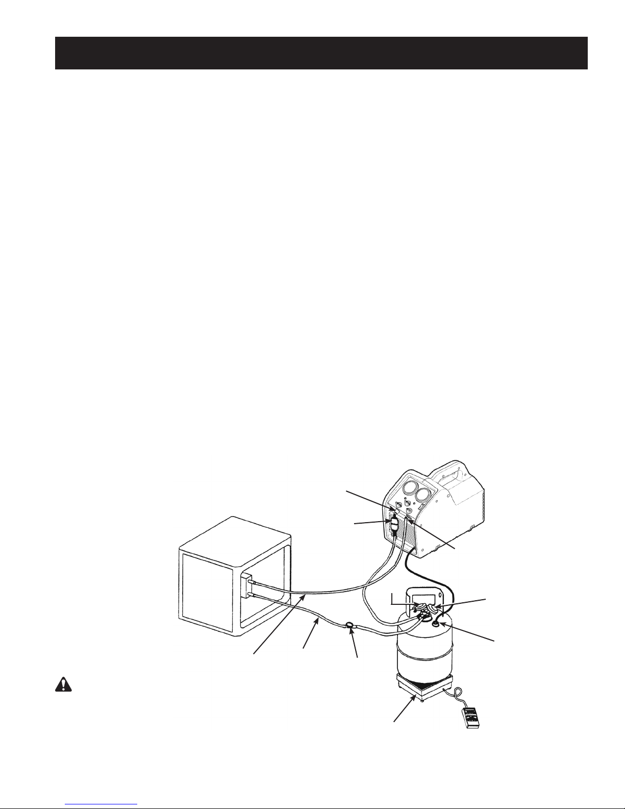
instrucciones de oPeración Para sistemas de lÍquido a granel
Procedimiento “Empuje – tire”
El método empuje - tire quita el líquido a granel del sistema utilizando la diferencia de presión creada por la
máquina de recuperación. Este método funciona solamente con sistemas grandes donde el líquido es fácilmente
accesible; puede no funcionar en sistemas que contengan menos de 15 libras de líquido a granel.
Este método se utiliza:
• en sistemas con cilindros receptores.
• en sistemas que contienen más de 20 libras de refrigerante.
• cuando se transere refrigerante líquido a granel de un cilindro a otro.
Recuperación de líquidos
1. Ubique la unidad RG6 en una supercie plana y
nivelada.
2. Conecte una manguera del adaptador de salida a la
unidad al puerto de vapores en el sistema al que se
le está haciendo el servicio.
3. Conecte la manguera del adaptador de entrada de
la unidad al puerto de vapores de un cilindro de
recuperación. Robinair recomienda utilizar un ltro /
secador en esta línea.
4. Conecte una manguera del lado líquido del cilindro
de recuperación al puerto líquido del sistema al que
se le está haciendo el servicio. Robinair recomienda
utilizar un vidrio visor en esta línea como método para
determinar cuando se ha quitado el líquido.
RG6 con el equipo SK-5001 instalado: una el
arnés para conexión del tanque (No. 549977) a la
conexión del conmutador interno en el cilindro de
recuperación.
5. Ubique el cilindro de recuperación en una balanza
(tal como TIF9010A) para evitar el llenado en
exceso del cilindro.
6. Verique que las válvulas de entrada y salida de la
unidad están cerradas.
7. Gire la perilla recuperación / purga a
RECUPERACIÓN.
8. Abra las válvulas del cilindro de recuperación.
9. Abra la válvula de salida de la unidad.
10. Gire el conmutador de energía a ENCENDIDO.
11. Abra LENTAMENTE la válvula de entrada en la
unidad.
12. Cuando el peso que se lee en la balanza deje de
incrementarse, cierre primero la válvula de entrada
en la unidad, luego cierre la válvula de líquido en el
cilindro de recuperación.
13. Gire el conmutador de energía a APAGADO.
14. Cierre las válvulas en el cilindro de recuperación y
cierre la válvula de salida de la máquina.
15. Proceda a la Recuperación de vapor.
Adaptador de
entrada
Sistema al que se le
está haciendo el
ADVERTENCIA: Cierre manualmente las válvulas tanto
en el cilindro de almacenamiento como en la unidad RG6,
para prevenir el llenado en exceso del cilindro. Una vez que
el sifón está en funcionamiento, puede llenar en exceso
el cilindro de almacenamiento, incluso si el cilindro está
equipado con un sensor de nivel de flotador. El sifón puede
continuar incluso cuando la máquina está apagada.
servicio
Vapor
Filtro / secador
Líquido
35
Vidrio
visor
Vapor
recuperación
Balanza
Cilindro de
Adaptador de salida
Líquido
Conexión del conmutador interno
(RG6 con el equipo SK-5001
instalado)
Page 36
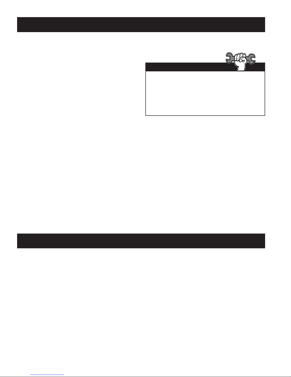
instrucciones de oPeración Para sistemas de lÍquido a granel
Recuperación de vapor
1. Ubique la unidad RG6 en una supercie plana
y nivelada.
2. Conecte una manguera del lado de entrada de
la unidad al puerto de líquidos en el sistema al
que se le está haciendo el servicio.
3. Conecte una manguera del lado de salida de
la unidad al puerto de líquidos en el cilindro de
recuperación.
PRECAUCIÓN: El cilindro de recuperación
debería estar en una balanza para evitar el
llenado en exceso del cilindro.
4. Abra la válvula de líquido en el cilindro de
recuperación.
5. Gire la perilla recuperación / purga a
RECUPERACIÓN.
6. Abra la válvula de salida de la unidad.
7. Gire el conmutador de energía a ENCENDIDO.
8. Abra lentamente la válvula de entrada en la
unidad.
9. Ponga en funcionamiento la unidad hasta
obtener el vacío deseado.
10. Cierre las válvulas de entrada y salida de la
unidad.
11. Gire el conmutador de energía a APAGADO.
12. Cierre los puertos en el cilindro de
recuperación.
Para un procedimiento de recuperación más
rápido, recupere tanto desde el puerto de líquido
como desde el de vapor en el sistema al que se le
está haciendo el servicio, utilizando un adaptador
en forma de T o un juego de indicadores del
colector en la conguración de las mangueras.
Recomendación técnica
Purgar gas no condensable de un cilindro de almacenamiento
1. Permita que el cilindro de almacenamiento
permanezca sin perturbaciones por 24 horas
para que el aire suba a la parte superior.
2. Conecte un juego de indicadores del conector
al cilindro. Lea la cantidad de presión en
el cilindro como se indica en la salida del
indicador de presión.
3. Determine la temperatura ambiente en la
habitación.
4. Consulte una tabla de presión / temperatura
del refrigerante y encuentre la temperatura
ambiente. Identique en la tabla la presión
correspondiente para el tipo de refrigerante en
el cilindro. Determine cómo se relaciona con
las lecturas en el indicador.
5. Si las lecturas de presión en el cilindro son
más altas que la presión que se muestra en la
tabla, abra MUY LENTAMENTE la válvulas del
puerto vapor. (Esto se hace lentamente para
causar la menor turbulencia posible dentro del
cilindro).
Observe decrecer la presión en el indicador.
Para prevenir la ventilación, agregue 4–5 psi a
la presión que se muestra en la tabla. Cuando
el indicador corresponde a esa presión, cierre
la válvula del puerto de vapor.
6. Permita que el cilindro se asiente por 10
minutos y luego revise la presión nuevamente.
7. Repita el proceso, si es necesario.
36
Page 37

información de cilindros de recuPeración
Tipo de cilindro
Utilice solamente cilindros de almacenamiento
de refrigerante rellenables autorizados. Las
regulaciones federales requieren que el refrigerante
sea transportado solamente en contenedores
que cumplen con las especicaciones del
Departamento de transporte. 4BW ó 4BA).
NUNCA use un cilindro estándar desechable de 30
libras (el tipo de contenedor en el que se vende el
refrigerante nuevo) para recuperar refrigerante.
Presión de trabajo
Los cilindros de recuperación están diseñados para
diferentes presiones de trabajo. Robinair recomienda
ampliamente usar los cilindros de 400 psi.
ADVERTENCIA: Para prevenir lesiones
personales, no exceda la tasa de presión de
trabajo del cilindro. Como mínimo, el RG6
requiere el uso de un cilindro de recuperación
de 350 psi.
NOTA: La utilización de un cilindro de 400 psi
es obligatoria cuando se está recuperando
refrigerante R-410A. Consulte la sección de
Partes y Accesorios de este manual para más
información.
Si anticipa temperaturas superiores a 57ºC (135ºF),
consulte al proveedor de refrigerante.
Capacidad
Los códigos de seguridad establecen que los
cilindros cerrados no deben ser llenados con líquidos
en más de un 80% del volumen. (El 20% restante se
llama espacio para presión de cabecera).
No exceda el 80% de la capacidad del cilindro.
Robinair recomienda el uso de la Balanza de
refrigerante TIF9010A para controlar la capacidad
del cilindro.
Refrigerantes
Cada cilindro y ltro / secador debe estar
designado para un sólo tipo de refrigerante.
Si usted debe utilizar un cilindro previamente usado
para un refrigerante diferente, prepare el cilindro
vaciándolo completamente, llevando a cabo una
evacuación, purgándolo usando nitrógeno seco y
luego llevando a cabo otra evacuación.
Almacenamiento
Almacene los cilindros de refrigerante en un lugar
fresco y seco.
Fugas
Algunos cilindros tienen válvulas que no fueron
jadas correctamente cuando fueron fabricadas.
Mantener las tapas en las válvulas va a protegerlas
de las fugas de refrigerante.
ADVERTENCIA: Para prevenir las lesiones personales, nunca transporte un
cilindro llenado en exceso. El refrigerante se expande cuando se calienta y puede
causar que un cilindro llenado en exceso explote.
Cilindro de almacenamiento Temperatura
16°C (60°F) 21°C (70°F) 38°C (100°F) 54°C (130°F) 65°C (150°F)
COMENZANDO CON EL CIL-
INDRO
80% POR VOLUMEN
Espacio ocupado por el líquido 80% 81% 83% 90% 94%
COMENZANDO CON EL CIL-
INDRO
90% POR VOLUMEN
Espacio ocupado por el líquido 90% 92% 96% 100%
37
Page 38
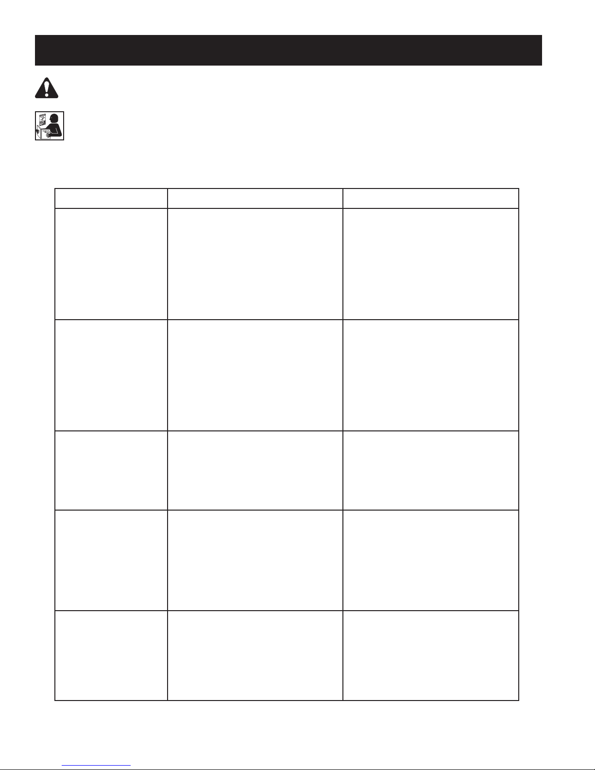
solución de Problemas
ADVERTENCIA: PARA EVITAR LESIONES PERSONALES Y / O DAÑO AL EQUIPO
PERMITA LA OPERACIÓN Y REPARACIÓN DE ESTA UNIDAD SOLAMENTE A PERSONAL
CALIFICADO. Antes de operar o reparar la unidad, lea y siga las instrucciones y advertencias de
este manual. El técnico debe estar familiarizado con los sistemas de aire acondicionado y refrigeración, refrigerantes y los peligros de los componentes presurizados. Si el técnico no puede leer este
manual, las instrucciones de funcionamiento y las precauciones de seguridad se deben leer y discutir
en el idioma nativo del técnico.
Síntoma Causa posible Solución posible
La unidad no se enciende
El compresor intenta
iniciar pero solamente
zumba
La máquina bombea
dentro de la válvula de
cierre de alta presión
Recuperación lenta 1. Líquido atrapado en el sistema.
El disyuntor del circuito
se mueve
1. El cable de energía no está
conectado.
2. Mala salida de energía.
3. La máquina está en apagado de
alta presión.
4. El motor está en una sobrecarga tér-
mica.
5. El disyuntor del circuito se
desconectó.
1. Bajo voltaje en la fuente de energía.
2. Cable de extensión demasiado
largo o demasiado pequeño.
3. Presión de cabecera demasiado alta.
1. La válvula de salida en la máquina
está cerrada.
2. La válvula del cilindro de recuper-
ación está cerrado.
3. Presión de cabecera demasiado alta.
2. Restricciones en el paso del ujo de
refrigerante.
1. Bajo voltaje en la fuente de energía.
2. Cable de extensión demasiado
largo o demasiado pequeño.
3. Carga excesiva en el compresor / mo-
tor.
1. Revise el cable de energía en la
pared y en la unidad.
2. Intente con una salida diferente.
3. Reduzca la presión de cabecera
hasta por debajo de los 400 psi.
4. Permita que el motor / la unidad se
enfríe.
5. Revise / reinicie el disyuntor del
circuito.
1. Ubique / utilice una salida mejor.
2. Reduzca el largo del cable de
extensión. Incremente el tamaño
(calibre) del cable de extensión
(14 AWG como mínimo).
3. Reduzca la presión de cabecera.
Gire la válvula de entrada
ligeramente pasando el cerrado
hacia PURGA para ecualizar la
presión de lado-alto / lado-bajo.
1. Revise la válvula de salida.
2. Revise la válvula del cilindro de
recuperación.
3. Revise las mangueras de salida por
restricciones o torceduras. Reduzca
la presión de cabecera.
1. Alterne momentáneamente el
compresor del sistema para mover
el refrigerante atrapado.
2. Revise las mangueras de entrada
por restricciones o torceduras. Quite
las válvulas Schrader y depresores
centrales de las mangueras (si
es posible). Use mangueras más
grandes.
1. Ubique / utilice una salida mejor.
2. Reduzca el largo del cable de
extensión. Incremente el tamaño
(indicador) del cable de extensión
(14 AWG como mínimo).
3. Reduzca la presión de cabecera.
Regule la válvula de entrada para
reducir la carga en el compresor.
38
Page 39
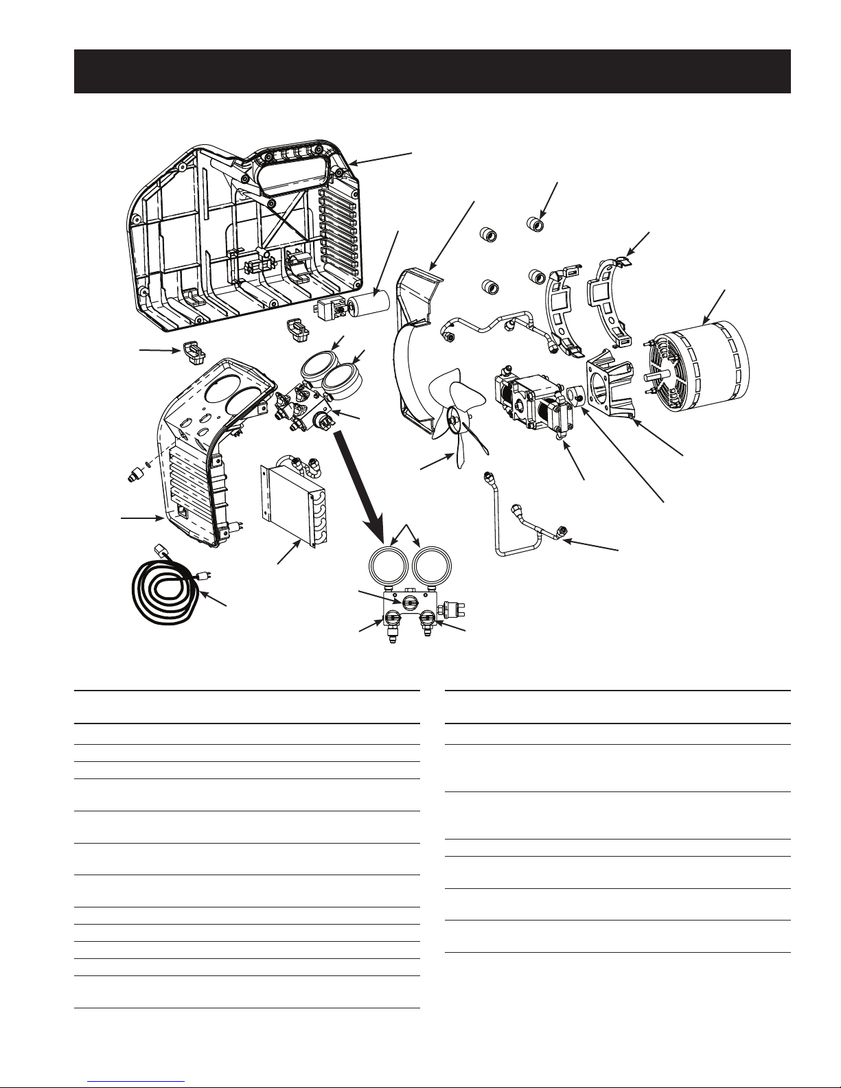
13
14
15
rePuestos
1 (mostrando el lado izquierdo)
2
Divisor
Relé del motor y
condensador
16
17
18
}
6
5
7
3
4
Interfaz del motor
Contrapeso
11
10
12
9
Artículo Nº de
parte parte Cant. Descripción
1 567913 1 Mitad de caja (izquierda)
567915 1 Mitad de caja (derecha)
2 550503 1 Pasacable (1 c/u.)
3 SK-6013 1 Equipo de abrazadera para motor
(4 piezas)
4 SK-6005 1 Equipo para motor (incluye motor,
relé, condensador, hardware)
5 SK-6023 1 Equipo para compresor (incluye compresor,
6 Sk-6008 1 Equipo para ventilador (incluye ventilador,
hardware de montaje del espaciador)
7 GA1000 1 Lentes del indicador (1 c/u.)
8 100124 1 Perilla del colector (rojo)
9 100123 1 Perilla del colector (azul)
10 100122 1 Perilla del colector (negro)
11 SK-6014 1 Equipo para condensador (incluye ensamblaje
hardware)
del condensador, hardware)
Tubos de entrada / salida
8
Artículo Nº de
parte parte Cant. Descripción
12 551628 1 Cable de energía
13 SK-6012 1 Equipo para bisel (incluye bisel, conmutador
de entrada de energía, hardware)
14 SK-6001 1 Adaptador de entrada / Equipo para pantalla
pantalla de ltro, juntas tóricas)
15 550502 1 Pie (1 c/u.)
16 SK-6003 1 Equipo para indicador de lado bajo
(incluye indicador de lado bajo, lentes)
17 SK-6022 1 Equipo para indicador de lado alto
(incluye indicador de lado alto, lentes)
18 SK-6016 1 Equipo para colector (incluye ensamblaje
del colector, hardware)
de energía, disyuntor de circuito, módulo
de ltro (incluye adaptador de entrada,
39
Page 40
equiPos de reconstrucción y accesorios
Nº de
parte Descripción
SK-5001 Equipo para cierre del tanque de 80%
SK-6001 Kit de reemplazo de pantalla de ltro
SK-6002 Equipo para ltro / secador (incluye ltro / secador, manguera de 6 pulgadas)
SK-6005 Kit de reemplazo del motor
SK-6007 Equipo para reconstrucción / reemplazo de válvula (incluye válvulas y resortes de
entrada / salida, juntas tóricas)
SK-6008 Kit de reemplazo del ventilador
SK-6012 Kit de reemplazo del bisel
SK-6014 Kit de reemplazo del condensador
SK-6015 Equipo para reconstrucción del sello del pistón (incluye sellos del pistón, junta tórica
energizante, bandas de desgaste)
SK-6016 Kit de reemplazo del distribuidor
SK-6023 Kit de reemplazo del compresor
SK-6022 Kit de reemplazo del calibrador
TIF9010A Balanza de refrigerante
17572 Cilindro de recuperación (capacidad de 50 libras, 400 psi de presión de trabajo,
sensor de capacidad)
SK-1013 Equipo do abrazadera del motor (4 pedazos)
40
Page 41
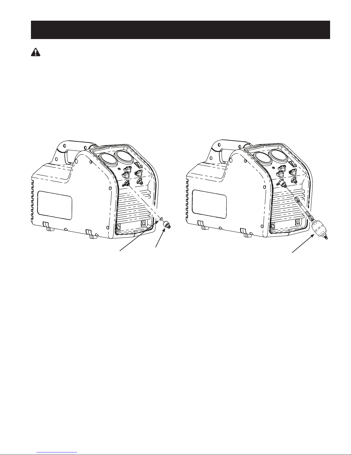
mantenimiento
PRECAUCIÓN: Para prevenir lesiones personales, desconecte el RG6 del suministro de energía
antes de llevar a cabo el mantenimiento.
Instalación del Filtro y del ltro / secador
1. Antes de llevar a cabo una recuperación de refrigerante, inspeccione y limpie siempre la pantalla del
filtro en el adaptador de la entrada en la unidad RG6. Reemplace la pantalla de filtro (número de parte
SK-6001) si es necesario. Una pantalla de filtro reduce ampliamente el riesgo de daño a la unidad
previniendo que materiales externos ingresen a la unidad y al sistema al que se le está haciendo el
servicio. No utilizar una pantalla de filtro invalidará la garantía.
Robinair también recomienda ampliamente usar un filtro / secador alineado (número de parte 100343)
en la línea de entrada.
Pantalla
del ltro
Adaptador
de entrada
Filtro / secador
número de parte 100343
Sistema quemado
1. Utilice dos ltros / secadores de capacidad ácida alta en series cuando se recupera un sistema
“quemado”. Robinair recomienda los ltros tipo Alco EK-162-F o tipo Sporlan C-162-F.
Una vez nalizada la recuperación del sistema, descargue el RG6 con una pequeña cantidad de
refrigerante y aceite de refrigerante limpios para purgar cualquier sustancia externa que haya quedado
en la unidad.
Almacenamiento
1. Vacíe el refrigerante de la unidad en un cilindro de almacenamiento. El refrigerante líquido que queda
en el condensador de la unidad puede expandirse, causando daños a los componentes.
2. Evacue completamente el RG6 de cualquier refrigerante residual y purgue con nitrógeno seco antes
de almacenarlo por un largo período de tiempo.
41
Page 42

42
Page 43

Station de récupération du fluide frigorigène
Model No. RG6
Manuel d’utilisation
43
Page 44

Mesures de sécurité
AVERTISSEMENT : POUR ÉVITER LES BLESSURES CORPORELLES ET/OU LE DOMMAGE À
L’ÉQUIPEMENT,
NE PERMETTRE QU’À UN EMPLOYÉ QUALIFIÉ D’UTILISER L’APPAREIL. Avant d’utiliser l’appareil,
il est impératif de lire et de suivre les directives et les avertissements contenus dans ce manuel.
L’opérateur doit connaître les systèmes de climatisation et de réfrigération, les réfrigérants et les
dangers représentés par les éléments sous pression. Si l’utilisateur est incapable de lire ce manuel,
les directives relatives au fonctionnement et les mesures de sécurité doivent être lues et discutées
dans la langue maternelle de l’utilisateur.
LE RÉSERVOIR SOUS PRESSION CONTIENT DU RÉFRIGÉRANT. Ne pas trop remplir la cuve
d’entreposage au risque de causer une explosion et des blessures, voire la mort. Ne pas récupérer
les uides frigorigènes dans des contenants non conçus à cet effet; n’utiliser que des contenants
réutilisables autorisés (spéc. DOT 4BW ou 4BA).
LES TUYAUX PEUVENT CONTENIR DU FLUIDE FRIGORIGÈNE SOUS PRESSION. Le contact
avec le uide frigorigène peut causer des blessures corporelles. Porter un équipement de protection,
y compris des lunettes de protection et des gants de sécurité. Usez d’extrême prudence lorsque vous
débranchez les tuyaux.
ÉVITEZ D’INHALER DU FLUIDE FRIGORIGÈNE POUR CLIMATISEUR ET DES VAPEURS DE
LUBRIFIANT. Une telle exposition peut irriter les yeux, le nez et la gorge. Pour purger le réfrigérant
du système de climatisation, n’utilisez que l’équipement certié pour le type de réfrigérant à vidanger.
Utilisez la machine dans des endroits pourvus d’une ventilation mécanique offrant au moins quatre
changements d’air par heure. En cas de décharge accidentelle, aérez l’aire de travail avant de
reprendre l’activité.
POUR RÉDUIRE LE RISQUE D’INCENCIE, UTILISEZ UNE RALLONGE LA PLUS COURTE
POSSIBLE DONT la TAILLE
inférieure pourrait causer la défaillance de l’équipement électrique.
POUR RÉDUIRE LES RISQUES D’INCENDIE, ne pas utiliser l’appareil à proximité de contenants
ouverts ou de déversements d’essence ou d’autres substances inammables.
MISE EN GARDE : NE PAS FAIRE UN ESSAI DE PRESSION OU DE FUITE DU MATÉRIEL OU DES
SYSTÈMES DE CLIMATISATION DU VÉHICULE SOUS PRESSION. Certains mélanges d’air et de
réfrigérant ont démontré qu’ils sont combustibles à pressions élevées. En prenant feu, ces mélanges
peuvent provoquer des dommages matériels ou des blessures physiques.
NE PAS MÉLANGER LES TYPES DE FLUIDES FRIGORIGÈNES UTILISÉS DANS UN SYSTÈME
OU UN MÊME CONTENANT. Le mélange de uides frigorigènes peut causer de graves dommages
à l’appareil et au système faisant l’objet de l’entretien.
LA TENSION ÉLEVÉE À L’INTÉRIEUR DE L’APPAREIL POSE UN RISQUE DE CHOC ÉLECTRIQUE.
Une exposition à ce choc peut causer des blessures. Débrancher l’alimentation avant de réparer
l’appareil.
MINIMALE EST DE 14 AWG. L’utilisation d’une rallonge d’une grosseur
Vous pouvez obtenir de plus amples informations sur la santé et la sécurité par
les fabricants de uides frigorigènes et de lubriants.
Explication dEs mots indicatEurs dE sécurité
AVERTISSEMENTS : indique une situation potentiellement dangereuse risquant, si elle n’est pas
évitée, de causer des blessures graves ou mortelles.
MISE EN GARDE : indique une situation potentiellement dangereuse risquant, si elle n’est pas
évitée, de causer des blessures modérées ou légères.
MISE EN GARDE : sans le symbole d’alerte, indique une situation potentiellement dangereuse risquant,
si elle n’est pas évitée, de causer des dommages matériels.
2
Page 45

table des Matières
Mesures de sécurité
Explication des mots indicateurs de sécurité
Comprendre la récupération du fluide frigorigène
Consignes d’utilisation standard
Configuration
Procédure de récupération
Purger la station RG6
Consignes d’utilisation des systèmes de liquides en vrac
Procédure Admission/Évacuation
Récupération de liquide
Récupération de vapeur
. . . . . . . . . . . . . . . . . . . . . . . . . . . . . . . .
. . . . . . . . . . . . . . . . . . .
. . . . . . . . . . . . . . . . .
. . . . . . . . . . . . . . . . . . . . . . . . . .
. . . . . . . . . . . . . . . . . . . . . . . . . . . . . . . .
. . . . . . . . . . . . . . . . . . . . . . . . .
. . . . . . . . . . . . . . . . . . . . . . . . . . .
. . . . . . . . . . . .
. . . . . . . . . . . . . . . . . . . . .
. . . . . . . . . . . . . . . . . . . . . . . . . .
. . . . . . . . . . . . . . . . . . . . . . . . . .
Purge de gaz non condensables à partir d’une bouteille d’entreposage
Renseignements sur la bouteille de récupération
Dépannage
Pièces de rechange
. . . . . . . . . . . . . . . . . . . . . . . . . . . . . . . . . . . .
. . . . . . . . . . . . . . . . . . . . . . . . . . . . . . . .
Ensembles de remise en état et accessoires
. . . . . . . . . . . . . . . . .
. . . . . . . . . . . . . . . . . . .
. . . . .
44
44
46
47
47
48
48
49
49
49
50
50
51
52
53
54
Entretien
. . . . . . . . . . . . . . . . . . . . . . . . . . . . . . . . . . . . . .
Installation du filtre et du déshydrateur-filtre
Système hors d’usage
Entreposage
Énoncé de la garantie
. . . . . . . . . . . . . . . . . . . . . . . . . . . . . . . .
. . . . . . . . . . . . . . . . .
. . . . . . . . . . . . . . . . . . . . . . . . . . .
. . . . . . . . . . . . . . . .
Intérieur du couvercle arrière
55
55
55
55
45
Page 46

coMprendre la récupération du fluide frigorigène
La récupération de uide frigorigène est le processus
par lequel le uide frigorigène est évacué du système
et entreposé dans une bouteille. Les données suivantes
sont essentielles pour obtenir les meilleurs résultats de
récupération possibles.
Fluide frigorigène
Identiez le type de uide frigorigène et la quantité qui se
trouve dans le système devant faire l’objet de l’entretien.
L’utilisation de la station RG6 est approuvée avec les uides
frigorigènes de catégorie III, IV et V (selon ARI-740) :
R-12, R-22, R-134a, R-401a, R-401b,R-401c, R-402a,
R-402b, R-404a, R-406a, R-407a, R-407b, R-407c,
R-407d, R-408a, R-409a, R-410a, R-411a, R-411b,
R-412a, R-500, R-502, R-507 R-509
Filtres et déshydrateurs-ltres
ATTENTION : les ltres empêchent les contaminants
d’entrer dans l’appareil, ce qui réduit les risques
d’endommager l’appareil et le système faisant l’objet
de l’entretien.
Un tamis est installé de série derrière le raccord
d’admission de la station RG6. Robinair recommande
fortement d’utiliser un tamis propre lors de chaque entretien.
Ne pas utiliser un tamis révoquera votre garantie.
Robinair recommande fortement d’utiliser un
déshydrateur-ltre (nº 100343, non fourni) sur le raccord
d’admission. Chaque ltre de conduite doit porter une
étiquette et être utilisé pour un seul type de uide frigorigène.
Robinets
AVERTISSEMENT : pour prévenir les blessures
corporelles, ouvrez LENTEMENT les robinets de
service et de bouteille de manière à pouvoir couper
rapidement l’écoulement des gaz au besoin. Après
s’être assuré qu’il est sécuritaire de le faire, il est
possible d’ouvrir les robinets complètement.
Isolez les volumes importants de uide frigorigène
et fermez les robinets après usage. De cette façon,
si une fuite venait à se former dans le système, le uide
frigorigène ne s’échapperait pas dans l’atmosphère.
Bouteilles d’entreposage
AVERTISSEMENT : une bouteille d’entreposage
est considérée pleine lorsque son volume atteint 80 %.
NE PAS TROP REMPLIR. En raison de la dilatation du
liquide, la bouteille risque d’exploser si elle est remplie
à un volume excédant 80 % et possiblement causer des
blessures corporelles et des dommages à l’équipement.
Utilisez une balance, comme la TIF9010A, pour éviter
de trop remplir la bouteille d’entreposage.
Robinair recommande d’utiliser l’ensemble de fermeture
à 80 % facultative (nº SK-5001) avec cet appareil. Une
fois l’ensemble installé et utilisé sur une bouteille de
récupération dotée d’un interrupteur à otteur interne,
l’appareil se ferme automatiquement lorsque la bouteille
est pleine à 80 %. (Votre appareil est précâblé en usine
pour fonctionner avec cet ensemble.)
Tuyaux
Les tuyaux doivent être équipés de raccord à faibles
pertes et afcher les pressions nominales appropriées
au uide frigorigène se trouvant dans le système faisant
l’objet de l’entretien.
Interrupteur de fermeture
Cet appareil est doté d’un interrupteur de fermeture interne
à haute pression. L’appareil se ferme si la pression du
système dépasse les 550 psi. L’interrupteur de fermeture
se réinitialise automatiquement lorsque la pression tombe
sous les 400 psi.
AVERTISSEMENT : l’interrupteur interne de
fermeture de la pression n’empêche PAS la bouteille de
trop se remplir. Si le système se ferme automatiquement
alors qu’il est connecté à une bouteille, il est possible
que celle-ci soit trop remplie. Prenez immédiatement
les mesures nécessaires pour relâcher la pression
élevée et/ou le trop-plein de la bouteille, sans quoi des
blessures pourraient survenir.
Procédure Admission/Évacuation
Au moment de récupérer des volumes importants
de liquide (plus de 7 kg (15 lb)), utilisez la méthode
Admission/Évacuation décrite dans ce manuel.
Taux de dépression et d’évacuation maximaux
Pour obtenir la dépression nale la plus importante,
utilisez une bouteille de récupération sous vide. Pour
maximiser les taux de récupération :
•
Utilisez un tuyau d’un diamètre de 9 mm (3/8 po)
ou plus le plus court possible. (Il est recommandé
d’utiliser un tuyau de 91 cm (3 pi) ou moins.)
•
Enlevez les régulateurs de débit inutiles du tuyau et
retirez les vannes Schrader des orifices de raccordement.
Les joints en caoutchouc déformés, les régulateurs de
débit des tuyaux et les vannes Schrader défectueuses ou
inutiles peuvent empêcher l’écoulement des liquides.
•
Si vous êtes certain que le uide frigorigène se
trouvant dans le système faisant l’objet de l’entretien
est propre ou neuf, il est possible de retirer le tamis du
raccord d’admission.
•
Purgez la station RG6 à la n de la phase de
récupération des vapeurs, tout particulièrement lors
de la récupération de grandes quantités de vapeur.
Procédez à une nouvelle purge une fois le processus
de récupération terminé et la dépression désirée
obtenue. Reportez-vous à la rubrique « Purger
la station RG6 » à la n de la section Consignes
d’utilisation standard.
Entretien
ATTENTION :
au système de réfrigération soient secs et propres.
Des dommages peuvent survenir si de l’humidité
s’introduit dans le système.
veillez à ce que tous les raccordements
46
Page 47

consignes d’utilisation standard
Raccord
Voyant
d’admission
Jeu de jauge
du collecteur
Système
faisant l’objet
de l’entretien
Vapeur
Déshydrateur-
Liquide
Balance
Les directives suivantes se rapportent à la procédure
de récupération standard ou « courante ».
Procédure de conguration
1. Placez la station RG6 sur une surface plane et
horizontale.
2. Assurez-vous qu’un tamis propre a été installé
derrière le raccord d’admission.
3. Branchez un tuyau entre le raccord de
refoulement de l’appareil et le port des liquides
de la bouteille de récupération.
4. Branchez un tuyau entre le raccord d’admission
de l’appareil et le port de sortie du jeu de jauge
du collecteur. Robinair recommande d’utiliser un
voyant et un déshydrateur-ltre sur cette conduite.
5. Branchez un tuyau entre la sortie des liquides (basse
pression) du jeu de jauge du collecteur et la sortie
des liquides du système faisant l’objet de l’entretien.
6. Branchez un tuyau entre la sortie de vapeur
(pression élevée) du jeu de jauge du collecteur
et la sortie de vapeur du système faisant l’objet
de l’entretien.
RG6 le kit SK-5001 étant installé : relier le
faisceau de connexion du réservoir (nº 549977)
à la connexion du contacteur à otteur sur la
bouteille de récupération.
7. Assurez-vous que les robinets d’admission et
d’échappement de la station RG6 sont bien
fermés.
8. Placez la bouteille de récupération sur une
balance (comme la TIF9010A) pour éviter de
trop remplir la bouteille.
ltre
Raccord de
Port
des
liquides
Bouteille de
récupération
refoulement
Connexion du contacteur
à otteur
(RG6 le kit SK-5001 étant
installé)
AVERTISSEMENT : une bouteille
d’entreposage est considérée pleine lorsque son
volume atteint 80 %. NE PAS TROP REMPLIR.
En raison de la dilatation du liquide, la bouteille
risque d’exploser si elle est remplie à un
volume excédant 80 % et possiblement causer
des blessures corporelles et des dommages à
l’équipement.
Conseils techniques
Le fonctionnement de la station RG6 est optimal
lorsque la tension de l’appareil (lorsqu’il est en
marche) se situe entre 115 VCA et 122 VCA. Des
tensions d’alimentation plus basses pourraient
causer des démarrages difciles sous une pression
de refoulement élevée, une performance réduite
et/ou la surchauffe du moteur.
Utilisez une sortie sur laquelle aucun autre appareil
n’est branché (par exemple, des dispositifs d’éclairage,
des machines, etc.).
N’utilisez aucune rallonge à moins que cela ne
s’avère nécessaire. Si une rallonge est utilisée,
elle doit être d’une grosseur minimale de 14 AWG
et être aussi courte que possible pour réduire les
chutes de tension.
47
Page 48
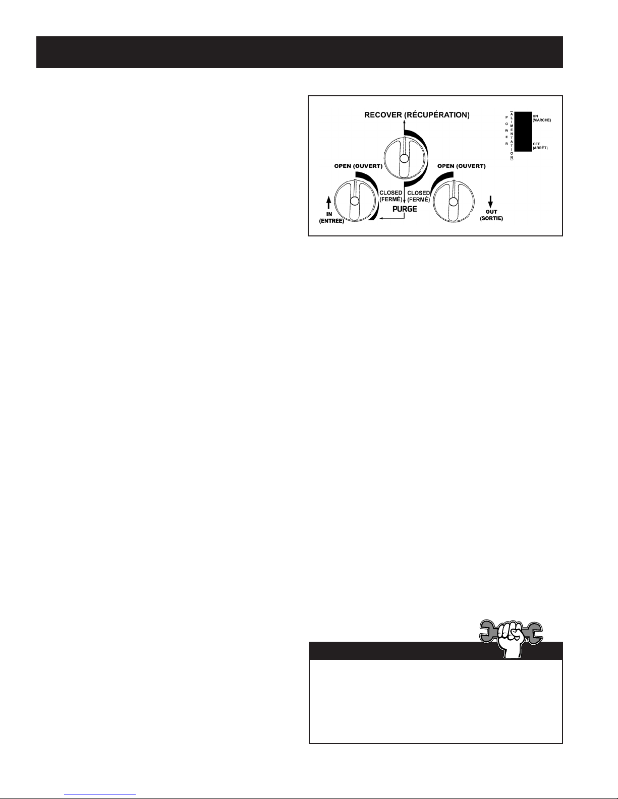
consignes d’utilisation standard
Procédure de récupération
1. Branchez l’appareil à une prise de 115 V.
2. Ouvrez lentement le robinet de liquide de la
bouteille de récupération après avoir vérié
l’étanchéité des tuyaux et des raccordements.
3. Réglez le robinet de récupération/purge de la
station RG6 à la position RECOVER.
4. Ouvrez le robinet de liquide du jeu de jauge
du collecteur. Remarque : l’ouverture du
robinet de liquide évacue d’abord le liquide
du système, réduisant ainsi le temps de
récupération de façon signicative.
5. Ouvrez le robinet d’échappement de la station RG6.
6. Placez l’interrupteur d’alimentation en position de marche (ON).
7. Ouvrez lentement le robinet d’admission de l’appareil. Remarque : si l’appareil fait entendre des
« cognements », réduisez (fermez) lentement le robinet d’admission jusqu’à ce que le bruit cesse.
8. Une fois le liquide évacué du système, ouvrez le robinet de vapeur du jeu de jauge du collecteur pour
naliser l’évacuation du système.
9. Faites fonctionner la station RG6 jusqu’à ce que la dépression désirée soit obtenue.
10. Fermez les robinets de vapeur et de liquide du jeu de jauge du collecteur.
11. Tournez le robinet d’admission de la station RG6 à la position fermé (CLOSED).
12. Placez l’interrupteur d’alimentation en position d’arrêt (OFF).
Purger la station RG6
ATTENTION : purgez toujours la station
RG6 après avoir terminé la procédure de
récupération. Le fait de ne pas purger le reste
du uide frigorigène de l’appareil pourrait
causer la dégradation acide des composantes
internes, entraînant au bout du compte une
défaillance prématurée de l’appareil.
1. Assurez-vous que les robinets de vapeur et de
liquide du jeu de jauge du collecteur sont bien
fermés (le cas échéant).
2. Fermez les robinets du système faisant l’objet
de l’entretien (le cas échéant).
3. Assurez-vous que le robinet d’échappement
de l’appareil est ouvert et que le robinet
d’admission est fermé.
4. Assurez-vous que le robinet de liquide de la
bouteille de récupération est ouvert.
5. Réglez le robinet de récupération/purge à la
position PURGE.
6. Placez l’interrupteur d’alimentation en position
de marche (ON).
7. Tournez lentement le robinet d’admission vers
la position PURGE. Alors que la pression
d’admission interne diminue, ouvrez le robinet
à la position de purge complète.
8. Faites fonctionner l’appareil jusqu’à ce que la
dépression désirée soit obtenue.
9. Fermez les robinets d’admission et
d’échappement de l’appareil.
10. Placez l’interrupteur d’alimentation en position
d’arrêt (OFF).
11. Fermez les ports de la bouteille de récupération.
12. Réglez le robinet de récupération/purge à la
position récupération (RECOVER).
13. Débranchez tous les accessoires et remplacez
le ltre de conduite.
Si vous avez de la difculté à démarrer ou redémarrer
l’appareil en raison d’une pression de refoulement
élevée, fermez d’abord le robinet d’admission. Tournez
ensuite lentement le robinet d’admission vers la
position de purge jusqu’à ce que la pression d’admission
augmente. Fermez de nouveau le robinet d’admission
et redémarrez l’appareil.
Conseil technique
48
Page 49
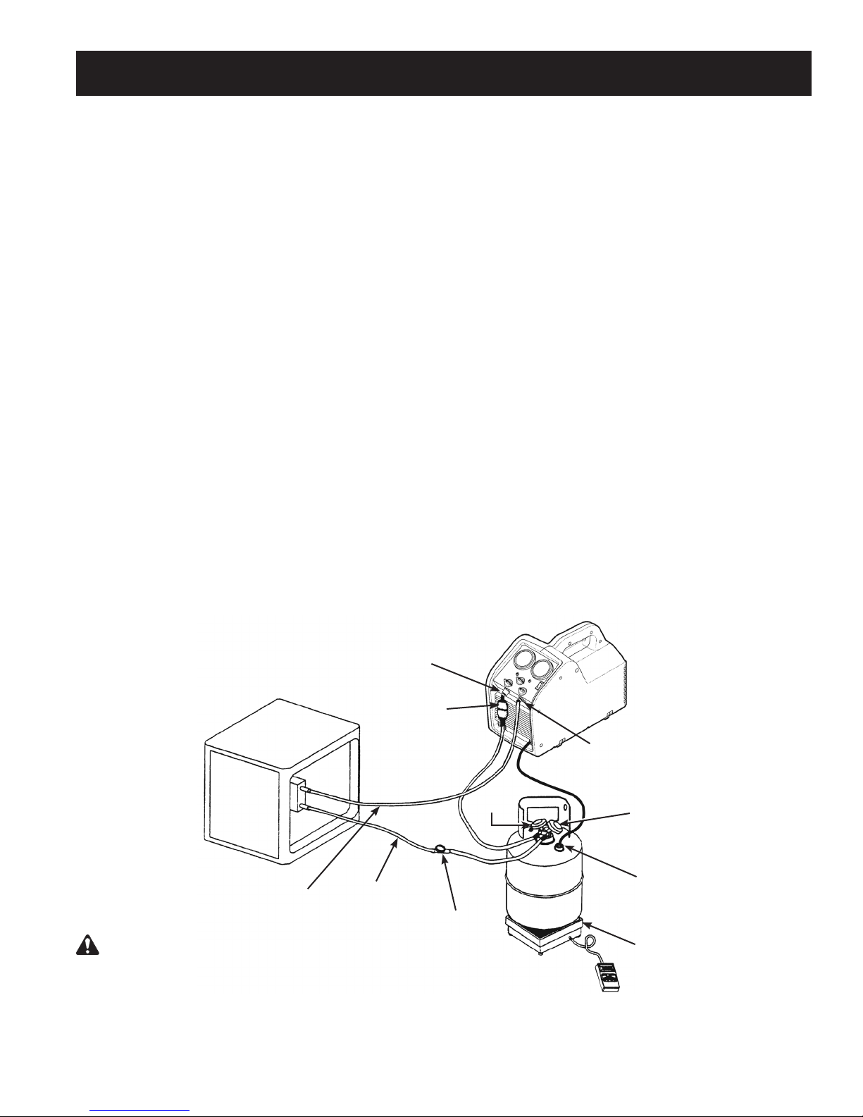
consignes d’utilisation des systèMes de liquides en vrac
Procédure Admission/Évacuation
La méthode Admission/Évacuation extrait les liquides en vrac du système grâce à la pression différentielle générée par la
station de récupération. Cette méthode ne fonctionne qu’avec de larges systèmes où le liquide est aisément accessible; elle
ne fonctionne pas sur des systèmes contenant moins de 7 kg (15 lb) de liquides en vrac.
Cette méthode est utilisée :
•
sur des systèmes équipés de bouteilles collectrices;
•
sur des systèmes contenant plus de 9 kg (20 lb) de liquide frigorigène;
•
au moment de transférer des uides frigorigènes en vrac d’une bouteille à l’autre.
Récupération de liquide
1. Placez la station RG6 sur une surface plane et horizontale.
2. Branchez un tuyau entre le raccord de refoulement de
l’appareil et le port des vapeurs du système faisant l’objet de
l’entretien.
3. Branchez un tuyau entre le raccord d’admission de l’appareil
et le port des vapeurs d’une bouteille de récupération.
Robinair recommande d’utiliser un déshydrateur-ltre sur
cette conduite.
4. Branchez un tuyau entre la sortie des liquides de la bouteille
de récupération et le port des liquides du système faisant
l’objet de l’entretien. Robinair recommande d’utiliser un
voyant sur cette conduite de manière à déterminer le
moment où le liquide est évacué.
RG6 le kit SK-5001 étant installé : relier le faisceau de
connexion du réservoir (nº 549977) à la connexion du
contacteur à otteur sur la bouteille de récupération..
5. Placez la bouteille de récupération sur une balance (comme
la TIF9010A) pour éviter de trop remplir la bouteille.
6. Assurez-vous que les robinets d’admission et
d’échappement de l’appareil sont bien fermés.
Raccord
d’admission
7. Tournez le bouton de récupération/purge à la position
récupération (RECOVER).
8. Ouvrez les robinets de la bouteille de récupération.
9. Ouvrez le robinet d’échappement de l’appareil.
10. Placez l’interrupteur d’alimentation en position de marche
(ON).
11. Ouvrez LENTEMENT le robinet d’admission de l’appareil.
12. Lorsque la lecture du poids afchée sur la balance cesse
d’augmenter, fermez d’abord le robinet d’admission de
l’appareil, puis le robinet des liquides de la bouteille de
récupération.
13. Placez l’interrupteur d’alimentation en position d’arrêt (OFF).
14. Fermez les robinets de la bouteille de récupération,
puis le robinet d’échappement de la station.
15. Effectuez la Récupération de vapeur.
Système faisant
l’objet de
l’entretien
Vapeur
AVERTISSEMENT : fermez manuellement les
robinets de la bouteille d’entreposage et de la station
RG6 afin d’éviter de trop remplir la bouteille. Lorsque le
siphon est en marche, il lui est possible de trop remplir
la bouteille d’entreposage, et ce, même si la bouteille est
dotée d’un capteur de hauteur de flotteur. Le siphon peut
fonctionner même si l’appareil est désactivé.
Déshydrateur-
ltre
Liquide
Voyant
49
Vapeur
Bouteille de
récupération
Raccord de
refoulement
Liquide
Connexion du contacteur
à otteur
(RG6- le kit SK-5001 étant
installé)
Balance
Page 50

consignes d’utilisation des systèMes de liquides en vrac
Récupération de vapeur
1. Placez la station RG6 sur une surface plane
et horizontale.
2. Branchez un tuyau entre le raccord d’admission
de l’appareil et le port des liquides du système
faisant l’objet de l’entretien.
3. Branchez un tuyau entre le raccord de
refoulement de l’appareil et le port des liquides
de la bouteille de récupération.
ATTENTION : la bouteille de récupération
doit se trouver sur une balance pour éviter
de trop la remplir.
4. Ouvrez le robinet des liquides de la bouteille de
récupération.
5. Tournez le bouton de récupération/purge à la
position récupération (RECOVER).
6. Ouvrez le robinet d’échappement de l’appareil.
7. Placez l’interrupteur d’alimentation en position
de marche (ON).
8. Ouvrez lentement le robinet d’admission de
l’appareil.
9. Faites fonctionner l’appareil jusqu’à ce que la
dépression désirée soit obtenue.
10. Fermez les robinets d’admission et
d’échappement de l’appareil.
11. Placez l’interrupteur d’alimentation en position
d’arrêt (OFF).
12. Fermez les ports de la bouteille de récupération.
Pour un processus de récupération plus rapide,
procédez à la récupération à partir des ports des
liquides et des vapeurs du système faisant l’objet
de l’entretien en incorporant un raccord en T ou une
jauge de collecteur à la conguration des tuyaux.
Conseil technique
purge de gaz non condensables à partir d’une bouteille d’entreposage
1. Laissez la bouteille d’entreposage reposer
pendant 24 heures an de permettre à l’air de
remonter à la surface.
2. Branchez un jeu de jauge de collecteur sur
la bouteille. Lisez la pression de la bouteille
indiquée sur le manomètre de sortie.
3. Déterminez la température ambiante de la pièce.
4. Reportez-vous au tableau de la pression/
température de uide frigorigène et repérez la
température ambiante. Lisez le tableau pour
trouver la pression correspondant au type de
liquide frigorigène contenu dans la bouteille.
Déterminez la façon dont cette valeur se rapporte
à la lecture prise sur le manomètre.
5. Si la lecture de la pression de la bouteille est
supérieure à la pression indiquée dans le
tableau, ouvrez TRÈS LENTEMENT le robinet
du port des vapeurs. (Il est impératif de le
faire lentement pour causer un minimum de
turbulence dans la bouteille.)
Vériez que la pression indiquée sur la jauge
diminue. Pour éviter l’évacuation de gaz, ajoutez
4 à 5 psi à la pression indiquée dans le tableau.
Lorsque la jauge correspond à cette pression,
fermez le robinet du port des vapeurs.
6. Laissez la bouteille reposer pendant 10 minutes,
puis vériez la pression de nouveau.
7. Répétez la procédure au besoin.
50
Page 51
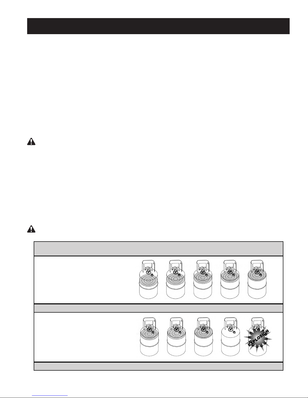
renseigneMents sur la bouteille de récupération
Type de bouteille
N’utilisez que des bouteilles d’entreposage de uides
frigorigènes réutilisables autorisées. Les lois fédérales
stipulent que le uide frigorigène doit être transporté
dans des contenants qui répondent aux spécications
DOT 4BW ou 4BA.
N’utilisez JAMAIS de bouteilles jetables standard
de 14 kg (30 lb) (le type de contenant dans lequel
le uide frigorigène est vendu) pour récupérer le
uide frigorigène.
Pression de service
Les bouteilles de récupération sont conçues
pour différentes pressions de service. Robinair
recommande fortement d’utiliser des bouteilles de
400 psi.
AVERTISSEMENT : pour prévenir les
blessures, n’excédez pas la pression de service
nominale de la bouteille. À tout le moins, la
station RG6 requiert l’utilisation d’une bouteille
de récupération de 350 psi.
REMARQUE : l’utilisation d’une bouteille de 400 psi
est obligatoire pour la récupération de uide
frigorigène R-410A. Reportez-vous à la section
Pièces et accessoires de ce manuel pour plus de
renseignements.
Si vous prévoyez des températures de plus de
57º C (135º F), consultez le fournisseur de uide
frigorigène.
Capacité
Les codes de sécurité stipulent que les bouteilles
fermées ne doivent pas être remplies de liquide à
un volume supérieur à 80 %. (Les 20 % restants
correspondent à une pression de refoulement
excédentaire.)
Ne dépassez pas 80 % de la capacité de la
bouteille. Robinair recommande d’utiliser la balance
pour uide frigorigène TIF9010A an de contrôler la
capacité de la bouteille.
Fluides frigorigènes :
Les bouteilles et les déshydrateurs-ltres doivent être
conçus pour un seul type de uide frigorigène.
Si vous devez réutiliser une bouteille pour un
uide frigorigène différent, préparez la bouteille
en la vidant complètement, en procédant à une
évacuation, en la purgeant avec de l’azote liquide,
puis en effectuant une nouvelle évacuation.
Entreposage
Entreposez les bouteilles de liquides frigorigènes
dans un endroit frais et sec.
Fuites
Certaines bouteilles sont équipées de robinets
n’ayant pas été fermés hermétiquement au moment
de leur fabrication. Le fait de conserver les bouchons
sur les robinets permettra d’empêcher la fuite de
uide frigorigène.
AVERTISSEMENT : pour prévenir les blessures, ne transportez jamais une bouteille trop pleine. Le fluide frigo-
rigène se dilate lorsqu’il devient chaud et risque de causer l’explosion de la bouteille si elle est trop remplie.
Bouteille d’entreposage Température 16º C 21º C 38º C 54º C 66º C
(60º F) (70º F) (100º F) (130º F) (150º F)
À PARTIR D’UNE
BOUTEILLE
DONT LE VOLUME
CORRESPOND À 80 %
Espace occupé par le liquide 80 % 81 % 83 % 90 % 94 %
À PARTIR D’UNE
BOUTEILLE
DONT LE VOLUME
CORRESPOND À 90 %
Espace occupé par le liquide 90 % 92 % 96 % 100 %
51
Page 52
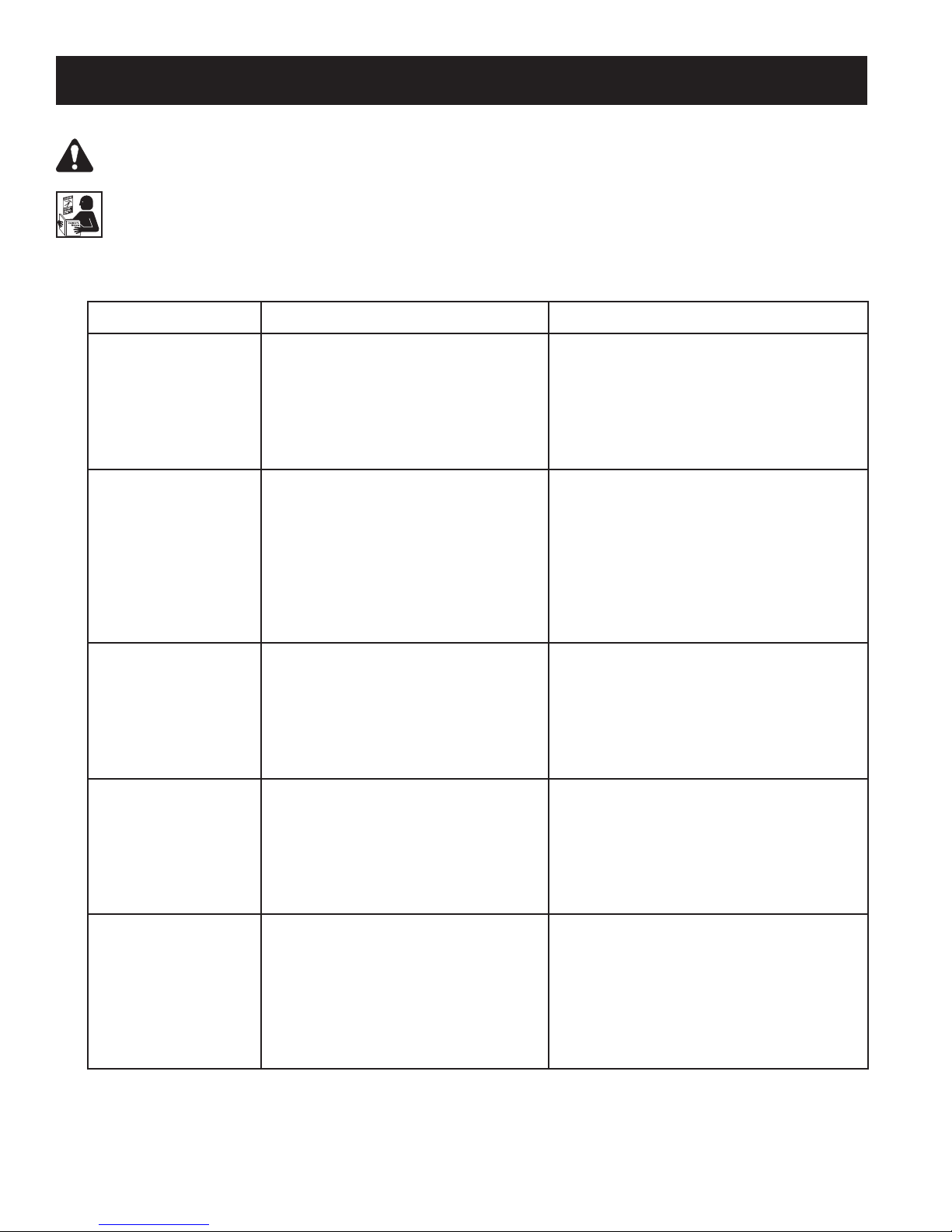
dépannage
AVERTISSEMENT : POUR ÉVITER LES BLESSURES CORPORELLES ET/OU TOUT DOMMAGE
À L’ÉQUIPEMENT :
NE PERMETTRE QU’À UN EMPLOYÉ QUALIFIÉ D’UTILISER ET DE RÉPARER CET APPAREIL.
Avant d’utiliser ou de réparer l’appareil, il est impératif de lire et de suivre les directives et les avertissements
contenus dans ce manuel. Le technicien doit être familier avec les systèmes de climatisation et de
réfrigération, les uides frigorigènes et les dangers représentés par les composants sous pression. Si
le technicien est incapable de lire ce manuel, les directives relatives au fonctionnement et les mesures
de sécurité doivent être lues et discutées dans la langue maternelle du technicien.
Symptôme Cause possible Solution possible
Impossible de mettre
l’appareil en marche
Le compresseur
tente de démarrer,
mais n’émet que des
bourdonnements
La station pompe
et est désactivée en
raison d’une pression
trop élevée.
Récupération lente 1. Liquide emprisonné dans le système.
Le disjoncteur se
déclenche
1. Le cordon d’alimentation n’est pas
branché.
2. La prise de courant est défectueuse.
3. L’appareil a été désactivé en raison
d’une pression trop élevée.
4. Le moteur est en surcharge thermale.
5. Le disjoncteur est déclenché.
1. Tension basse au niveau de la source
d’alimentation.
2. Rallonge trop longue ou trop petite.
3. Pression de refoulement trop élevée.
1. Le robinet d’échappement de la station
est fermé.
2. Le robinet de la bouteille de
récupération est fermé.
3. Pression de refoulement trop élevée.
2. Obstruction dans la voie de passage
du uide frigorigène.
1. Tension basse au niveau de la
source d’alimentation.
2. Rallonge trop longue ou trop petite.
3. Charge excessive du compresseur
ou moteur.
1. Vérier le cordon d’alimentation au
niveau de la prise murale et de l’appareil.
2. Brancher dans une autre prise de courant.
3. Réduire la pression de refoulement à
moins de 400 psi.
4. Laisser le moteur/l’appareil se refroidir.
5. Vérier/réinitialiser le disjoncteur.
1.
Localiser/utiliser une prise plus adéquate.
2. Réduire la longueur de la rallonge. Augmenter
la taille (calibre) de la rallonge (14 AWG
minimum).
3. Réduire la pression de refoulement. Tournez
l
e robinet légèrement vers la position PURGE
pour équilibrer la pression des côtés basse
et haute pressions.
1. Vérier le robinet d’échappement.
2. Vérier le robinet de la bouteille de
récupération.
3. S’assurer que les tuyaux d’échappement ne
sont ni obstrués, ni tordus. Réduire la
pression de refoulement.
1. Faire momentanément fonctionner le
compresseur du système pour libérer
le uide frigorigène emprisonné.
2. S’assurer que le tuyau d’admission n’est ni
obstrué, ni tordu. Retirer les vannes Schrader
et les régulateurs de débit des tuyaux (si
possible). Utiliser des tuyaux plus gros.
1. Localiser/utiliser une prise plus adéquate.
2. Réduire la longueur de la rallonge.
Augmenter la taille (calibre) de la rallonge
(14 AWG minimum).
3. Réduire la pression de refoulement. Fermer
le robinet d’admission pour réduire la charge
sur le compresseur.
52
Page 53
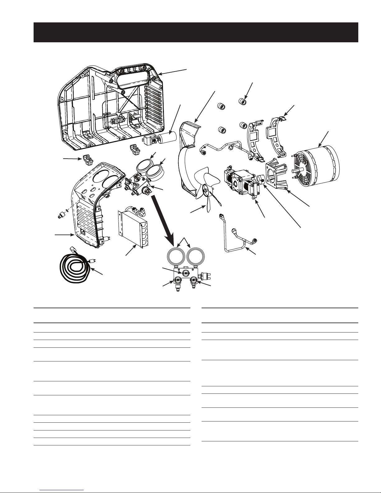
13
14
15
pièces de rechange
1 (côté gauche illustré)
2
Relais et
condensateur
du moteur
16
17
18
}
6
7
Diviseur
3
4
Interface du moteur
5
Contrepoids
11
10
12
9
No No
d’article de pièce Qté Description
1 567913 1 Demi-boîtier (gauche)
567915 1 Demi-boîtier (droit)
2 550503 1 Rondelle isolante (1 ch.)
3 SK-6013 1 Ensemble de bornes de moteur
(4 pièces)
4 SK-6005 1 Ensemble pour moteur (comprend
moteur, relais, condensateur,
matériel)
5 SK-6023 1 Ensemble pour compresseur
(comprend compresseur, matériel)
6 Sk-6008 1 Ensemble pour ventilateur
(comprend ventilateur, matériel de
montage pour entretoise)
7 GA1000 1 Lentille pour jauge (1 ch.)
8 100124 1 Bouton de collecteur (rouge)
9 100123 1 Bouton de collecteur (bleu)
10 100122 1 Bouton de collecteur (noir)
Tuyaux d’admission/
d’échappement
8
No No
d’article de pièce Qté Description
11 SK-6014 1 Ensemble pour condensateur
12 551628 1 Cordon d’alimentation
13 SK-6012 1 Ensemble pour collerette (comprend
collerette, interrupteur, disjoncteur,
module d’alimentation, matériel)
14 SK-6001 1 Ensemble pour raccord
d’admission/tamis (comprend
raccord d’admission, tamis, joint
torique)
15 550502 1 Pied (1 ch.)
16 SK-6003 1 Ensemble pour jauge côté bas
(comprend jauge côté bas, lentille)
17 SK-6022 1 Ensemble pour jauge côté haut
(comprend jauge côté haut, lentille)
18 SK-6016 1 Ensemble pour collecteur
(comprend assemblage du
collecteur, matériel)
53
Page 54

enseMbles de reMise en état et accessoires
No
de pièce Description
SK-5001 Ensemble de fermeture du réservoir à 80 %
SK-6001 Ensemble de remplacement du tamis
SK-6002 Ensemble pour déshydrateur-ltre (comprend déshydrateur-ltre, tuyau de 15 cm (6 po))
SK-6005 Ensemble de remplacement du moteur
SK-6007 Ensemble de remise en état/de remplacement pour robinet (comprend robinets
d’admission/d’échappement, ressorts, joints toriques)
SK-6008 Ensemble de remplacement du ventilateur
SK-6012 Ensemble de remplacement de la collerette
SK-6014 Ensemble de remplacement du condensateur
SK-6015 Ensemble de remise en état pour joint de piston (comprend joints de piston, joint
torique activateur, bande d’usure)
SK-6016 Ensemble de remplacement du collecteur
SK-6023 Ensemble de remplacement du compresseur
SK-6022 Ensemble de remplacement de la jauge %
TIF9010A Balance pour uide frigorigène
17572 Bouteille de récupération (capacité de 23 kg (50 lb), pression de service de 400 psi,
capteur de capacité)
SK-1013 Kit de bride de moteur (4 parties)
54
Page 55

entretien
ATTENTION : pour prévenir les blessures, débranchez la station RG6 du bloc d’alimentation
avant de procéder à l’entretien.
Installation du ltre et du déshydrateur-ltre
1. Avant de procéder à la récupération du fluide frigorigène, vérifiez et nettoyez toujours le tamis dans
le raccord d’admission de la station RG6. Remplacez le tamis (nº SK-6001) au besoin. Un tamis
réduit de façon significative les risques d’endommager l’appareil en empêchant les corps étrangers
de pénétrer dans l’appareil et dans le système faisant l’objet de l’entretien. Ne pas utiliser un tamis
révoquera la garantie.
Par ailleurs, Robinair recommande fortement d’installer un déshydrateur-filtre de conduite (nº 100343)
dans la conduite d’admission.
Tamis
Raccord
d’admission
Déshydrateur-ltre
nº 100343
Système hors d’usage
1. Utilisez en série deux déshydrateurs-ltres à haute capacité acide au moment de procéder à la
récupération d’un système « hors d’usage ». Robinair recommande des ltres Alco de type EK-162
ou Sporlan de type C-162.
Après avoir terminé la récupération du système, rincez la station RG6 avec une petite quantité
de uide frigorigène et d’huile frigorigène propres an de purger tout corps étranger de l’appareil.
Entreposage
1. Videz le uide frigorigène de l’appareil dans une bouteille d’entreposage. Le uide frigorigène
se trouvant toujours dans le condensateur de l’appareil risque de se dilater et d’endommager les
composantes.
2. Évacuez complètement la station RG6 de tout uide frigorigène et purgez l’appareil avec
de l’azote sec avant de l’entreposer pour une période prolongée.
55
Page 56

56
Page 57
Page 58

Page 59

full one-year limited Warranty
einjährige garantie
Unit Serial No.
This product is warranted to be free from defects in workmanship, materials and
components for a period of one year from date of purchase.
The following restrictions apply:
1. This warranty is non-transferable. All warranty claims must be made within the
warranty period. Proof of purchase must be supplied with the product when returned.
2. The warranty applies to product in normal use only, as described in this operating
manual. The product must be maintained and serviced as specied.
3. If the product fails, it will be repaired or replaced at the option of the manufacturer
(Robinair). Warranty service claims are subject to factory inspection for product
defects. The manufacturer is the sole determiner of warranty coverage. If during the
warranty evaluation it is determined that proper maintenance was not performed, or
that the product has been used in any way other than the purpose for which it was
designed, the manufacturer reserves the right to void the warranty.
4. Normal wear items (seals, lters, etc.) are specically excluded from this warranty,
unless found by the manufacturer to be defective.
This warranty does not apply if the product or product part is damaged by accident, misuse,
tampering with, or modifying in anyway. The manufacturer is not responsible for any
additional costs associated with a product failure including, but not limited to, loss of work
time, loss of refrigerant, or unauthorized shipping and/or labor charges.
Use of this product with any unauthorized refrigerants or chemicals will void the warranty.
Warranty Service:
1. Outside of the United States of America, contact your local Robinair distributor.
2. Inside the United States of America, call 1-800-327-5060 for a Return Material
Authorization (RMA) number. Instructions on where to send the product will be
provided.
Serien-Nr. des Geräts
Es wird garantiert, dass dieses Produkt während des Zeitraums von einem Jahr ab Kaufdatum
frei von Material-, Komponenten- und Verarbeitungsfehlern ist.
Es gelten folgende Beschränkungen:
1. Diese Garantie ist nicht übertragbar. Alle Garantieansprüche müssen innerhalb der
Garantieperiode eingereicht werden. Beim Umtausch muss der Kaufbeleg vorgelegt
werden.
2. Diese Garantie gilt für ein Produkt, das gemäß den Anweisungen in dieser
Bedienungsanleitung verwendet wurde. Das Produkt muss gemäß den
Anweisungen gewartet und instandgesetzt werden.
3. Bei einem Ausfall des Produkts wird es nach Ermessen des Herstellers (Robinair)
repariert oder ausgetauscht. Reparaturansprüche unter der Garantie unterliegen
einer werksseitigen Inspektion auf Produktschäden. Allein der Hersteller kann die
Garantiedeckung bestimmen. Wenn im Laufe der Inspektion festgestellt wird, dass
keine ordnungsgemäßen Wartungsarbeiten durchgeführt wurden oder dass das
Produkt auf eine andere Art und Weise verwendet wurde als die, für die sie konzipiert
wurde, behält sich der Hersteller das Recht vor, die Garantie für ungültig zu erklären.
4. Normale Verschleißteile (Dichtungen, Filter usw.) sind von der Garantie
ausgeschlossen, es sei denn, sie wurden vom Hersteller für defekt befunden.
Diese Garantie wird ungültig, wenn das Produkt oder dessen Teile durch Unfall oder falschen
Gebrauch beschädigt, manipuliert oder modiziert wurde. Der Hersteller kommt nicht für
Nebenkosten auf, die durch den Produktausfall entstehen, einschließlich, aber nicht beschränkt
auf, Arbeitsausfall, Verlust von Kältemittel oder nicht autorisierte Versand- und/oder
Arbeitskosten.
Bei Verwendung dieses Produkts mit nicht zugelassenen Kältemitteln oder Chemikalien
wird die Garantie ungültig.
Reparaturen unter der Garantie:
1. Außerhalb der Vereinigten Staaten wenden Sie sich an Ihren Robinair
Vertriebshändler.
2. Innerhalb der Vereinigten Staaten rufen Sie 1 800-327-5060 (gebührenfrei) an
und lassen sich eine RMA-Nummer (Rücksendenummer) geben. Sie erhalten
Anweisungen darüber, wohin Sie das Produkt senden können.
garantie limitée comPlète d’un an garantía limitada comPleta Por un año
Nº de série de l’appareil
Ce produit est garanti contre les défauts matériels et de fabrication pour une durée d’un an
à compter de la date d’achat.
Toutefois, les restrictions suivantes s’appliquent :
1. Cette garantie est non transférable. Toute réclamation au titre de la garantie doit être
soumise durant la période de garantie. La preuve d’achat doit être fournie avec le
produit lors d’un retour.
2. La garantie s’applique uniquement au produit utilisé dans des conditions de
fonctionnement normales conformément au manuel d’utilisation. Il doit être entretenu et
réparé conformément aux spécications.
3. Si le produit fait l’objet d’une défaillance, il sera réparé ou remplacé à la discrétion du
fabricant (Robinair). Les réclamations au titre de la garantie sont sujettes à l’inspection
en usine du produit défectueux. La couverture de la garantie est à la seule discrétion
du fabricant. Si l’évaluation de la garantie démontre qu’aucun entretien approprié n’a
été effectué ou que le produit a été utilisé dans un but autre que celui pour lequel il a
été conçu, le fabricant se réserve le droit d’annuler la garantie.
4. Les composants d’usure normale (joints, ltres, etc.) sont exclus de cette garantie,
à moins que le fabricant ne constate qu’ils sont défectueux.
Cette garantie n’est pas applicable si le produit ou les éléments du produit sont endommagés
à la suite d’un accident, d’un usage abusif, d’une altération ou d’une modication quelconque.
Le fabricant ne peut être tenu responsable de tout coût supplémentaire lié à la défaillance
du produit incluant, sans toutefois s’y limiter, les interruptions de fonctionnement, la perte de
uide frigorigène, la contamination des uides frigorigènes et l’expédition et/ou les frais de
main-d’œuvre soumis par des ateliers non autorisés.
L’utilisation de ce produit avec des uides frigorigènes ou produits chimiques non autorisés
annulera la garantie.
Assistance à la garantie :
1. À l’extérieur des États-Unis, communiquez avec le concessionnaire Robinair de votre
région.
2. Aux États-Unis, composez le 1-800-327-5060 pour obtenir un numéro d’autorisation
de retour d’article. Des directives sur l’endroit où retourner le produit vous seront
fournies.
Número de serie de la unidad
Se garantiza que este producto no posee defectos de mano de obra, materiales y
componentes por el período de un año a partir de la fecha de compra.
Aplican las siguientes restricciones:
1. Esta garantía no es transferible. Todo reclamo de garantía se debe hacer dentro del
período de garantía. Se debe proveer un comprobante de compra con el producto al
devolverlo.
2. La garantía aplica al producto en uso normal únicamente, como lo indica este manual
de funcionamiento. El producto debe contar con un servicio y mantenimiento según lo
especicado.
3. Si falla el producto, será reparado o reemplazado a discreción del fabricante
(Robinair). Los reclamos de servicio de garantía están sujetos a inspección autorizada
de defectos del producto. El fabricante es el único determinante de la cobertura de la
garantía. Si durante la evaluación de la garantía se determina que no se ha llevado a
cabo el mantenimiento apropiado, o que el producto ha sido utilizado para diferentes
propósitos de los que fue diseñado, el fabricante se reserva el derecho de invalidar
esta garantía.
4. Los elementos normales de desgaste (sellos, ltros, etc.) están especícamente
excluidos de la garantía, a menos que el fabricante los encuentre defectuosos.
Esta garantía no se aplica si el producto o parte del producto es dañado accidentalmente,
por uso inadecuado o ha sido alterado o modicado de cualquier manera. El fabricante
no es responsable de los costos adicionales relacionados con fallas en el producto, que
incluyen pero no se limitan a: tiempo improductivo, pérdida de refrigerante o envío no
autorizado y/o cargos por mano de obra.
La utilización de este producto con cualquier refrigerante o químico no autorizado invalidará
esta garantía.
Servicio de garantía:
1. Fuera de los Estados Unidos de América, contacte a su distribuidor de Robinair local.
2. Dentro de los Estados Unidos de América, llame al 1-800-327-5060 para obtener un
número de Autorización de retorno de material (RMA). Se proveerán instrucciones
sobre a dónde enviar el producto.
Page 60

655 EISENHOWER DRIVE
OWATONNA, MN 55060 USA
TECH SERVICES 800 822 5561
FAX 866 259 1241
CUSTOMER SERVICE 800 533 6127
FAX 800 322 2890
www.robinair.com
Form No. 567912
Rev. A, December 31, 2013
© Bosch Automotive Service Solutions LLC
 Loading...