

Page 1
Page 2
CONTENTS
Section
Title
Page
1
.
SPECIFICATIONS
.......................................................................................................
1
2
.
PERFORMANCE
........................................................................................................
3
2-1 MAXIMUM OUTPUT
........................................................................................................
3
2-2
CONTINUOUS RATED OUTPUT
....................................................................................
3
2-3 MAXIMUM TORQUE
.......................................................................................................
3
2-4 PERFORMANCE CURVES
.............................................................................................
4
3
.
FEATURES
..................................................................................................................
6
4
.
GENERAL DESCRIPTION OF ENGINE COMPONENTS
..........................................
7
4-1 CYLINDER AND CRANKCASE
.......................................................................................
7
4-2 MAIN BEARING COVER
.................................................................................................
7
4-3 CRANKSHAFT
..................................................................................................................
7
4-4 CONNECTING ROD AND PISTON
.................................................................................
8
4-5 PISTON
RINGS
...............................................................................................................
8
4-6 CAMSHAFT
.....................................................................................................................
8
4-7 VALVE ARRANGEMENT
.................................................................................................
9
4-8 CYLINDER HEAD
............................................................................................................
9
4-9 GOVERNOR SYSTEM
....................................................................................................
9
4-10 COOLING SYSTEM
.....................................................................................................
10
4-11 LUBRICATION SYSTEM
..............................................................................................
10
4-12 IGNITION SYSTEM
.....................................................................................................
10
4-13 CARBURETOR
.............................................................................................................
11
4-14 AIR CLEANER
..............................................................................................................
11
4-1
5
BALANCER
...................................................................................................................
11
4-16 DECOMPRESSION SYSTEM
.....................................................................................
12
4-17 SECTIONAL VIEW OF ENGINE
..................................................................................
13
5
.
DISASSEMBLY AND REASSEMBLY
.......................................................................
15
5-1 PREPARATIONS AND SUGGESTIONS
........................................................................
15
5-2 SPECIALTOOLS
...........................................................................................................
15
5-3
DISASSEMBLY PROCEDURES
....................................................................................
16
5-4 REASSEMBLY PROCEDURES
.....................................................................................
31
5-5
BREAK-IN OPERATION
................................................................................................
43
6 .
MAGNETO
................................................................................................................
43
6-1
OPERATION AND FUNCTION
......................................................................................
43
6-2
BASIC THEORY
............................................................................................................
43
6-3
WIRING DIAGRAM
........................................................................................................
45
Page 3
Section
Title
Page
7 . AUTOMATIC DECOMPRESSION SYSTEM
............................................................
46
8
.
CARBURETOR
........................................................................................................
47
8-1
OPERATION AND CONSTRUCTION
............................................................................
47
8-2 DISASSEMBLY AND REASSEMBLY
.............................................................................
48
9
.
STARTING SYSTEM
................................................................................................
50
9-1 RECOIL STARTER
........................................................................................................
50
9-2 ELECTRIC STARTER
....................................................................................................
54
10
.
TROUBLESHOOTING
...........................................................................................
56
10-1 STARTING DIFFICULTIES
..........................................................................................
56
10-2 ENGINE MISFIRE
........................................................................................................
57
10-3 ENGINE
STOPS
..........................................................................................................
57
10-4 ENGINE OVERHEAT
...................................................................................................
58
10-5 ENGINE KNOCKS
.......................................................................................................
58
10-6 ENGINE BACKFIRES THROUGH CARBURETOR
.....................................................
58
11
.
INSTALLATION
.....................................................................................................
59
11-1 INSTALLING
.................................................................................................................
59
11-2 VENTILATION
..............................................................................................................
59
11 -3 EXHAUST GAS DISCHARGE
.....................................................................................
59
11 -4 POWER TRANSMISSION TO DRIVEN MACHINES
...................................................
59
12
.
SERVICE DATA
.......................................................................................................
60
12-1 CLEARANCE DATAAND LIMITS
................................................................................
60
12-2 TORQUE SPECIFICATIONS
.......................................................................................
66
12-3 OIL GRADE CHART
....................................................................................................
66
13
.
MAINTENANCE AND STORAGE
..........................................................................
67
13-1 DAILY MAINTENANCE
................................................................................................
67
13-2 INITIAL
20
HRS . MAINTENANCE
...............................................................................
67
13-3 EVERY
50
HRS
.
(10 DAYS) MAINTENANCE
.............................................................
67
13-4 EVERY
100-200
HRS . (MONTHLY) MAINTENANCE
.................................................
68
13-5 EVERY
500-600
HRS . MAINTENANCE
......................................................................
68
13-6 EVERY 100
HRS
.
(YEARLY) MAINTENANCE
............................................................
68
13-7 ENGINE STORAGE
...........................................
:
.........................................................
68
Page 4
I
EH36
1
MODEL
~~~ ~ ~
EH36B
EH36DS EH36D
EH36BS
I
I
I
Type
Air-Cooled, 4-Cycle, Single-Cylinder,
Horizontal P.T.O. Shaft, OHV Gasoline Engine
Bore
x
Stroke
8.3
Compression Ratio
404 cm3 (24.65 cu.in.)
Piston Displacement
89
x
65 mm (3.50 x 2.56 in.)
Continuous
6.3
kW
(8.5 HP)
/3600
r.p.m. 6.3 kW (8.5
HP)
/I800
r.p.m.
output
Max.
8.5 kW (1 1.5
HP)
/3600 r.p.m.
8.5 kW
(1
1.5
HP)
/1800 r.p.m.
~
Max. Torque
54.9
N
-
m
(5.60
kgf
-
m)
/1250 r.p.m.
27.4
N
-
m (2.80 kgf m)
/2500
r.p.m.
I
Direction
of
Rotation
1
Counterclockwise As Viewed From P.T.O.
Shaft
Side
I
____~
Cooling system
Valve Arrangement
Forced Air Cooling
Automobile Oil SAE
#20,
#30 or 1OW-30 ; Class
SE
or higher
Lubricant
Splash Type Lubrication
Overhead Valve
~_____
Capacity of Lubricant 1.2 liters (0.32
U.S.
gal.)
Carburetor
I
Horizontal Draft, Float Type
Fuel
Fuel Tank Capacity
Gravity Type
Fuel Feed System
31
0
g/kW
-
h
(230 g/HP
-
h)
At Continuous Rated Output Fuel Consumption Ratio
Automobile Unleaded Gasoline
7.0 liters
(1.85
U.S.
gal.)
Ignition System
I
Flywheel Magneto (Solid State)
I
Spark Plug NGK BP6ES
Charging Capacity
-
-
1/2
Camshaft Drive
Speed Reduction
Starting System
12V-1.3A
-
1
2V-
1.3A
Governor System
Centrifugal Flyweight Type
Air Cleaner
Double Element Type
Recoil
Starter
&
Recoil Stafler
&
Recoil Starter
Recoil
Starter
Electric Starter
Electric Starter
Dry Weight
I
32.0 kg (70.6
Ib.)
I
35.0 kg (77:2 Ib.) I 31
.O
kg (68.4 Ib.) I 34.0 kg
(75.0
Ib.)]
~_____
Dimensions
(L
x W x
H)
389 mm x 431 mm x 433 mm (15.31
in.
x
16.97 in.
x
17.05
in.)
I
Specifications are subject
to
change
without
notice.
-
1-
Page 5
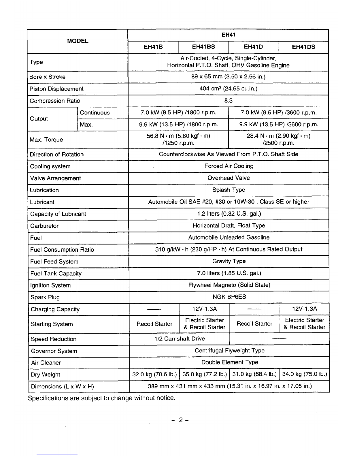
EH41
I
MODEL
EH41 B
EH41
DS
EH41
D
EH41 BS
Air-Cooled, 4-Cycle, Single-Cylinder,
Horizontal P.T.O. Shaft, OHV Gasoline Engine
I
Bore x Stroke
89
x
65
mm
(3.50 x 2.56 in.)
btonbisplacement
404 cm3 (24.65 cu.in.)
1
Empression Ratio
~~
8.3
I
Continuous
7.0 kW
(9.5
HP) 13600 r.p.m.
7.0 kW
(9.5
HP) /1800 r.p.m.
Output
Max.
9.9
kW (13.5 HP) /3600 r.p.m.
9.9
kW (13.5 HP) /1800 r.p.m.
,
Max. Torque
56.8
N
m
(5.80 kgf - m)
I
28.4
N
-
m (2.90 kgf m)
/1250 r.p.m.
/2500
r.p.m.
Direction
of
Rotation
Cooling system
Counterclockwise
As
Viewed From P.T.O. Shaft Side
Splash Type
Lubrication
Overhead Valve
Valve Arrangement
Forced Air Cooling
(Lubricant
I
Automobile Oil
SAE
#20, #30 or low-30 ; Class
SE
or
higher
I
Capacity
of
Lubricant
310 g/kW
-
h (230 g/HP - h) At Continuous Rated Output
Fuel Consumption Ratio
Automobile Unleaded Gasoline
Fuel
Horizontal Draft, Float Type
Carburetor
1.2 liters (0.32
U.S.
gal.)
/
7
I
Fuel Feed System
T~-
Gravity Type
1
7.0 liters (1.85
US.
gal.)
Ignition System
Spark Plug
Flywheel Magneto (Solid State)
12V-1.3A 12V-1.3A
-
Charging Capacity
NGK
BPGES
Starting System
Speed Reduction
1/2 Camshaft Drive
-
Governor System
Centrifugal Flyweight Type
Air Cleaner
Double Element Type
Electric Starter
&
Recoil Starter
Recoil
Starter
&
Recoil Starter
Recoil
Starter
Electric Starter
Dry Weight
Dimensions
(L
x W x
H)
389 mm x 431 mm
x
433 mm (1 5.31 in. x 16.97 in. x 17.05 in.)
~ ~~
32.0 kg (70.6
Ib.)
34.0 kg
(75.0
Ib.)
31.0 kg (68.4
Ib.)
35.0 kg (77.2
Ib.)
Specifications
are
subject
to change without
notice.
/"
-
2-
Page 6
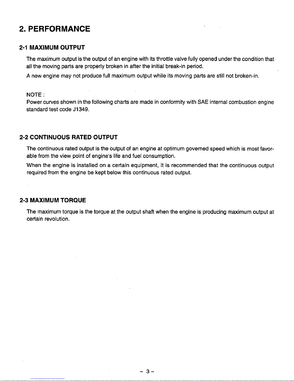
2.
PERFORMANCE
2-1
MAXIMUM OUTPUT
The maximum output is the output of an engine with its throttle valve fully opened under the condition that
all
the moving parts are properly broken in after the initial break-in period.
A
new engine may not produce full maximum output while its moving parts are still not broken-in.
NOTE
:
Power curves shown in the following charts are made in conformity with
SAE
internal combustion engine
standard test code
J
1349.
2-2
CONTINUOUS
RATED
OUTPUT
The continuous rated output
is
the output of an engine at optimum governed speed which is most favor-
able from the view point of engine's life and fuel consumption.
When the engine is installed on a certain equipment, it is recommended that the continuous output
required from the engine be kept below this continuous rated output.
2-3
MAXIMUM TORQUE
The maximum torque is the torque at the output shaft when the engine is producing maximum output at
certain revolution.
-
3-
Page 7
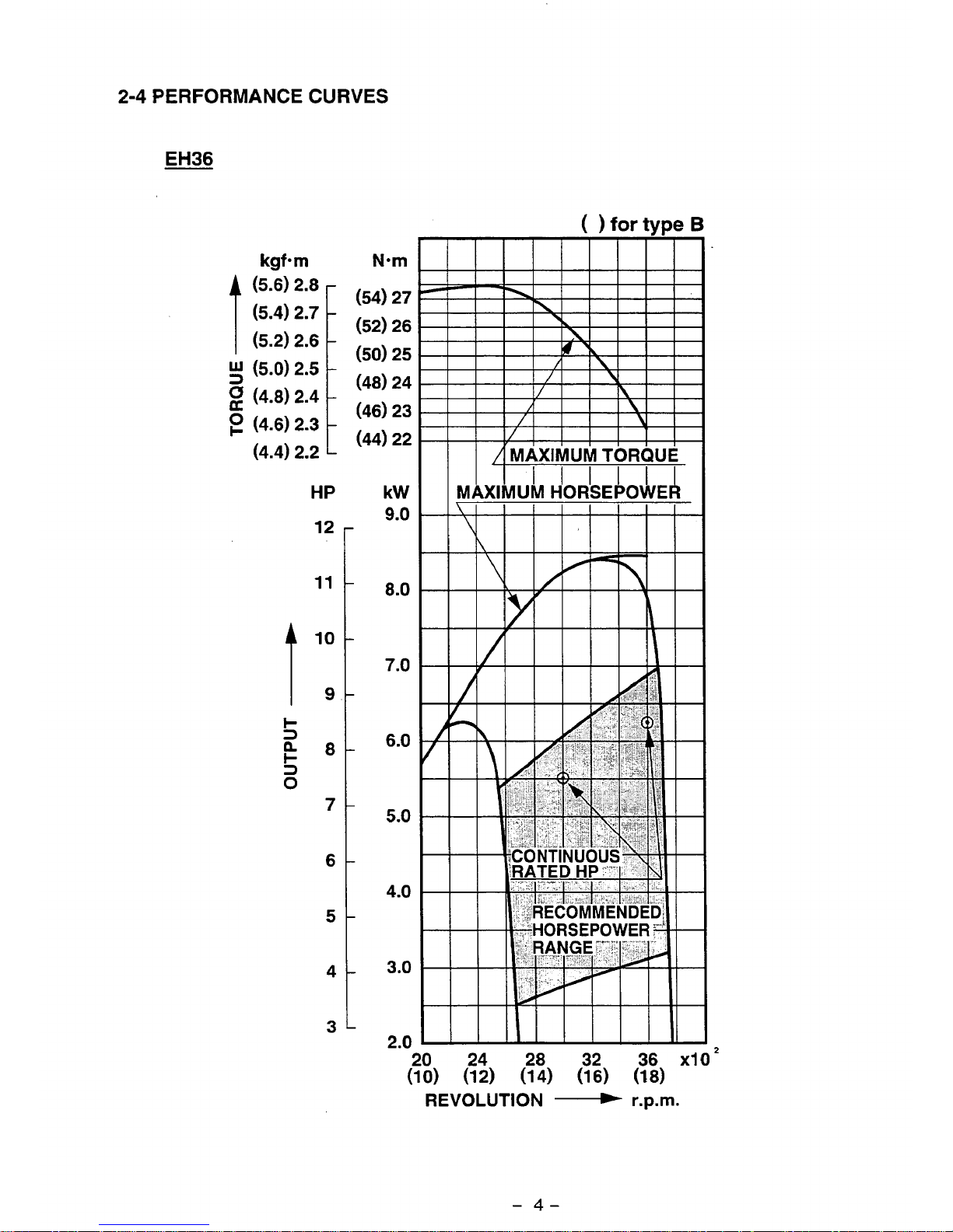
2-4
PERFORMANCE
CURVES
EH36
( )
for
type
B
t
kgf-m
(5.6) 2.8
(5.4) 2.7
(5.2) 2.6
!!j
(5.0) 2.5
(4.8) 2.4
(4.6)
2.3
(4.4) 2.2
HP
12
11
10
9
8
7
6
5
4
3
Nom
:54) 27
:52) 26
:50)
25
:48) 24
:46)
23
(44) 22
kW
9.0
8.0
7.0
6.0
5.0
4.0
3.0
2.0
24
(1 2)
28
(1
4)
32
(1
6)
36
(1
8)
REVOLUTION
r.p.m.
-
4-
Page 8
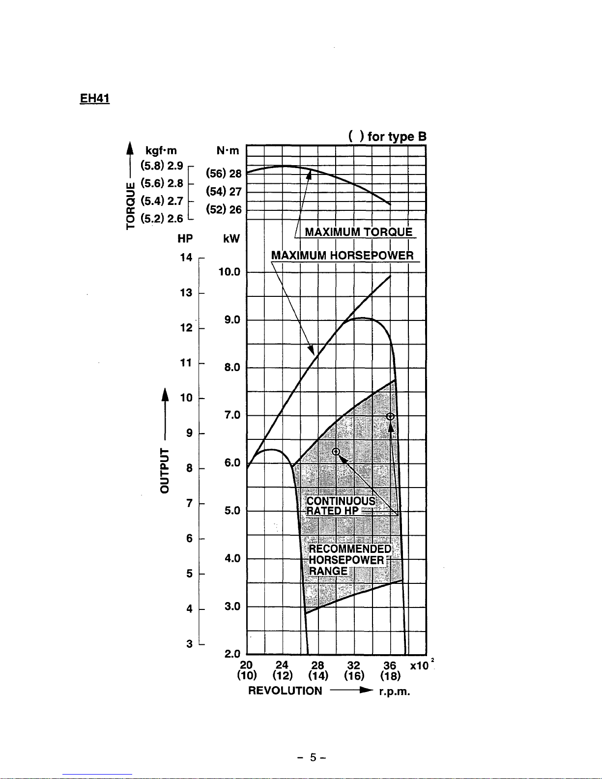
EH41
kgfom
(5.8)
2.9
1
w
(5.6) 2.8
-
(5.2) 2.6
I-
HP
14
13
12
11
10
9
8
7
6
5
4
3
(
for
tvpe
B
Nom
(56)
28
(54)
27
(52)
26
kW
10.0
9.0
8.0
7.0
6.0
5.0
4.0
3.0
2.0
20
24 28 32 36
x10
’
(10)
(12) (14) (16) (18)
REVOLUTION
r.p.m.
-
5-
Page 9
1.
The overhead valve design offers a compactness, light weight and ideal combustion characteristics
resulting in more power from less fuel and prolonged engine life.
2.
The adoption of an inclined cylinder offers low height
of
engine, making the arrangements for installing
the engine much easier for various powered equipments.
3.
The vibration, free design with a balancer system and lighter reciprocating parts.
4.
Combustion and mechanical noises have been analized acoustically and improved
for
better tonal
quality and lower engine noise.
5.
The automatic decompression system lightens the recoil pull force by
50%
comparing to the conven-
tional
SV
engine.
-
6-
Page 10
4.
GENERAL DESCRIPTION
OF
ENGINE COMPONENTS
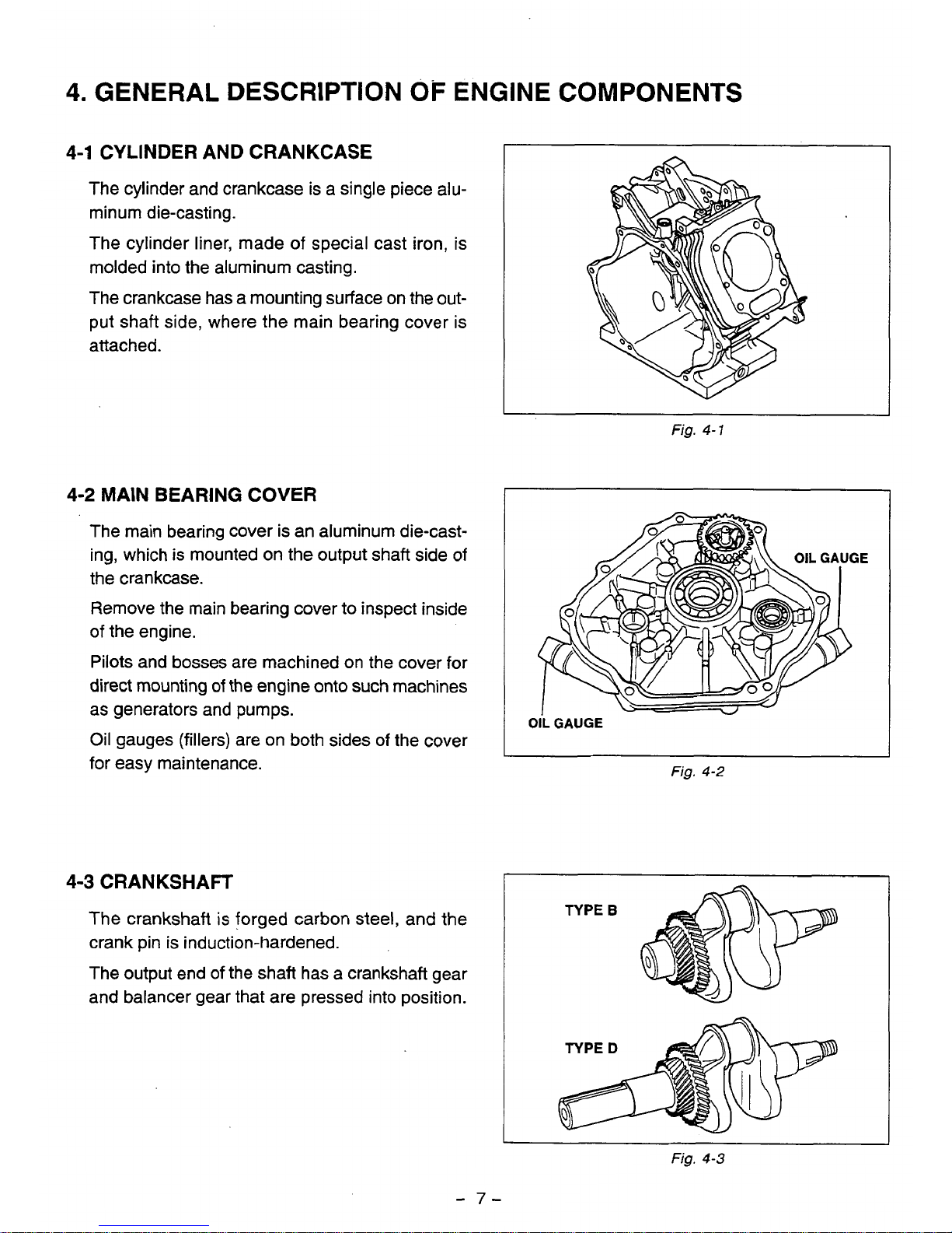
4-1
CYLINDER AND CRANKCASE
The cylinder and crankcase is a single piece alu-
minum die-casting.
The cylinder liner, made of special cast iron, is
molded into the aluminum casting.
The crankcase has a mounting surface on the out-
put shaft side, where the main bearing cover is
attached.
I
Fig.
4-
1
4-2
MAIN BEARING
COVER
The main bearing cover is an aluminum die-casting, which is mounted on the output shaft side of
the crankcase.
Remove the main bearing cover to inspect inside
of
the engine.
Pilots and bosses are machined
on
the cover for
direct mounting
of
the engine onto such machines
as generators and pumps.
Oil gauges (fillers) are on both sides of the cover
for easy maintenance.
I
OilGAUGE
-
Fig.
4-2
4-3
CRANKSHAFT
The crankshaft
is
forged carbon steel, and the
crank pin is induction-hardened.
The output end
of
the shaft has a crankshaft gear
and balancer gear that are pressed into position.
Fig.
4-3
-
7-
Page 11
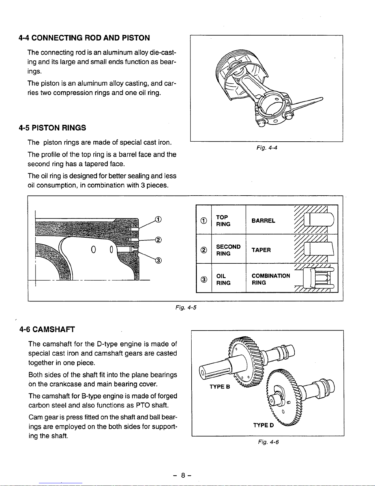
4-4
CONNECTING ROD AND
PISTON
The connecting rod is an aluminum alloy die-casting and its large and small ends function as bear-
ings.
The piston is an aluminum alloy casting, and car-
ries
two
compression rings and one oil ring.
4-5
PISTON
RINGS
The piston rings are made
of
special cast iron.
The profile of the top ring is a barrel face and the
second ring has a tapered face.
The oil ring is designed for better sealing and less
Fig.
4-4
oil consumption, in combination with 3 pieces.
TOP
BARREL
@
RING
TAPER
@
RING
OIL
COMBINATION
@
RING
RING
4-6
CAMSHAFT
The camshaft for the D-type engine is made of
special cast iron and camshaft gears are casted
together in one piece.
Both sides
of
the shaft fit into the plane bearings
on the crankcase and main bearing cover.
The camshaft for B-type engine is made of forged
carbon steel and also functions as
PTO
shaft.
Cam gear
is
press fitted on the shaft and ball bearings are employed on the both sides for supporting the shaft.
I
I
Fig.
4-5
Fig.
4-6
-
8-
Page 12
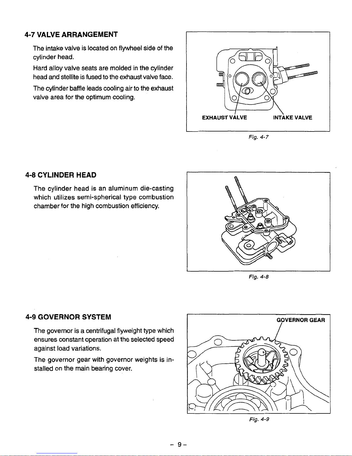
The intake valve is located on flywheel side of the
cylinder head.
Hard alloy valve seats are molded in the cylinder
head and stellite is fused to the exhaust valve face.
The cylinder baffle leads cooling air to the exhaust
valve area for the optimum cooling.
EXHAUST VALVE INTAKE VALVE
Fig.
4-7
4-8
CYLINDER
HEAD
The cylinder head is an aluminum die-casting
which utilizes semi-spherical type combustion
chamber for the high combustion efficiency.
Fig.
4-8
4-9
GOVERNOR
SYSTEM
The governor is a centrifugal flyweight type which
ensures constant operation at the selected speed
against load variations.
The governor gear with governor weights is in-
stalled on the main bearing cover.
~
"
GOVERNOR
GEAR
/
Fig.
4-9
-
9-
Page 13
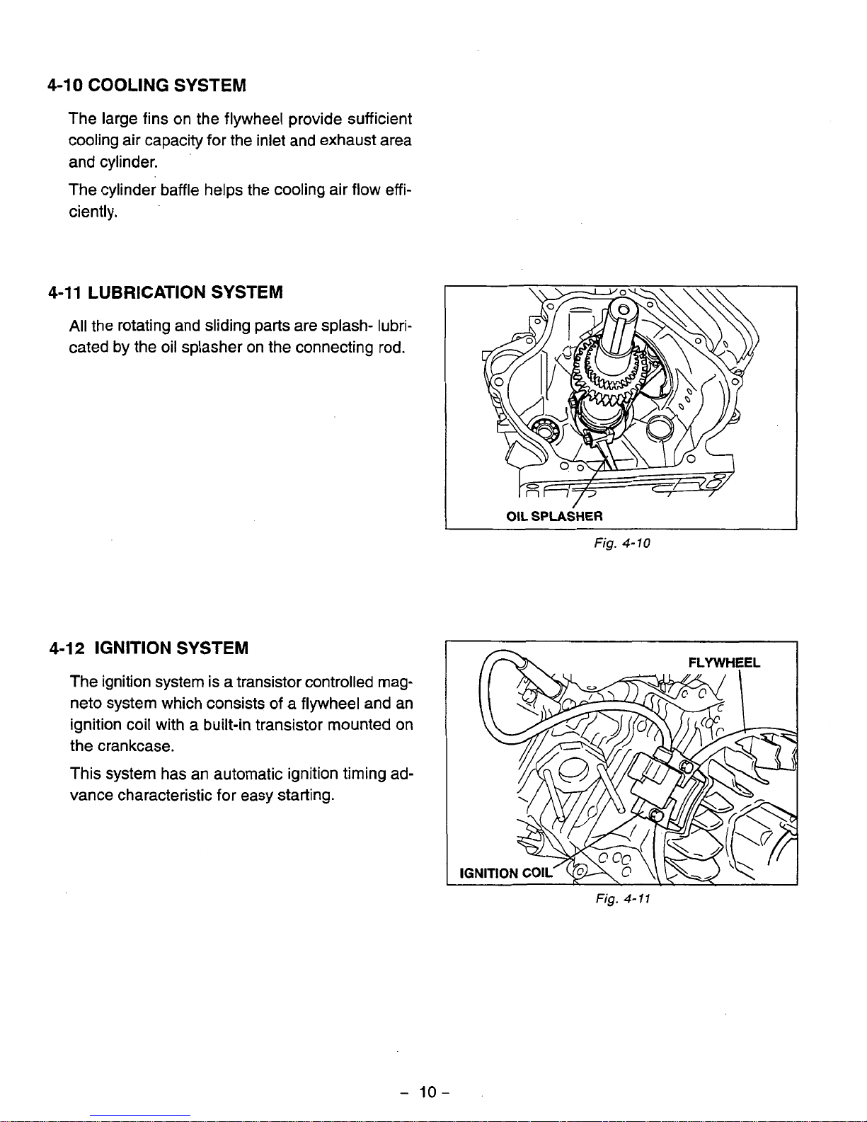
4-10
COOLING
SYSTEM
The large fins on the flywheel provide sufficient
cooling air capacity for the inlet and exhaust area
and cylinder.
The cylinder baffle helps the cooling air flow effi-
ciently.
4-11
LUBRICATION
SYSTEM
All
the rotating and sliding parts are splash- lubri-
cated by the
oil
splasher on the connecting rod.
I
OIL
SPLASHER
4-12
IGNITION SYSTEM
The ignition system is a transistor controlled rnag-
net0 system which consists of a flywheel and an
ignition coil with a built-in transistor mounted
on
the crankcase.
This system has an automatic ignition timing advance characteristic for easy starting.
Fig.
4-
10
FLYWHEEL
I
Fig.
4-
11
P
-
10-
.
Page 14
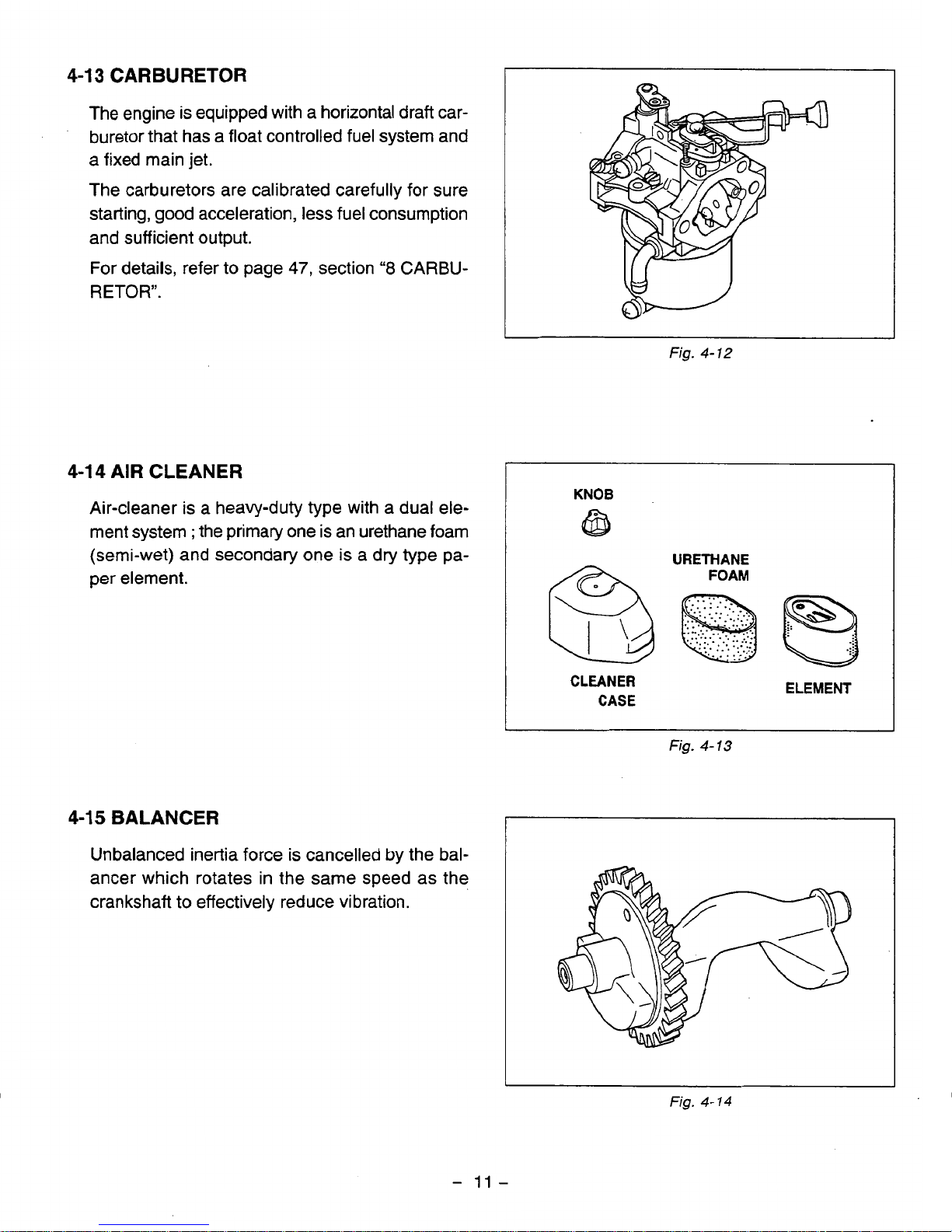
4-13 CARBURETOR
The engine is equipped with a horizontal draft car-
buretor that has a float controlled fuel system and
a
fixed main jet.
The carburetors are calibrated carefully for sure
starting, good acceleration, less fuel consumption
and sufficient output.
For
details, refer to page
47,
section
"8
CARBU-
RETOR''.
Fig.
4-72
4-1 4 AIR CLEANER
KNOB
Air-cleaner
is
a heavy-duty type with a dual ele-
ment system
;
the primary one is an urethane foam
per element.
URETHANE
(semi-wet) and secondary one
is
a dry type pa-
&
FOAM
CLEANER
CASE
ELEMENT
Fig.
4-
13
4-15 BALANCER
I
Unbalanced inertia force is cancelled
by
the balancer which rotates in the same speed as the
crankshaft to effectively reduce vibration.
Fig.
4-14
-
11
-
Page 15
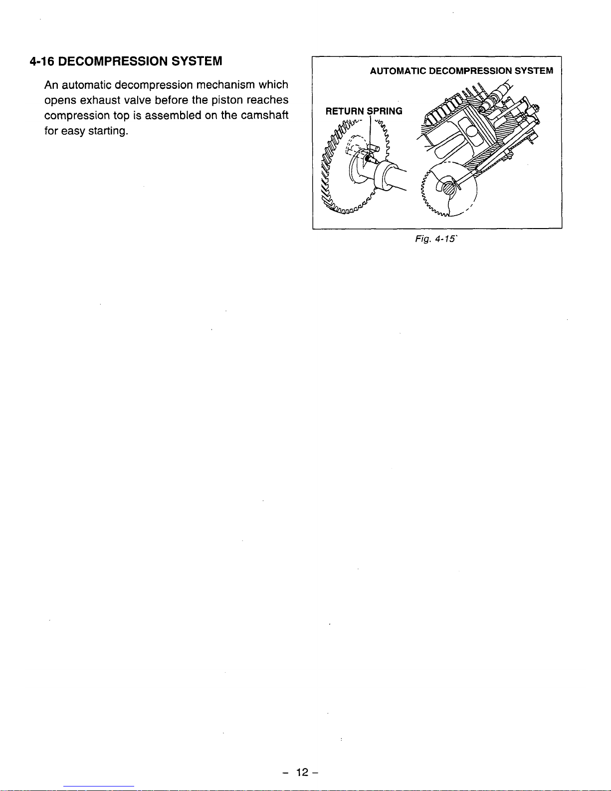
4-16
DECOMPRESSION
SYSTEM
AUTOMATIC
DECOMPRESSION
SYSTEM
An automatic decompression mechanism which
opens exhaust valve before the piston reaches
compression top
is
assembled
on
the
camshaft
for
easy starting.
RETURN SPRING
Fig.
4-
15'
-
12-
Page 16
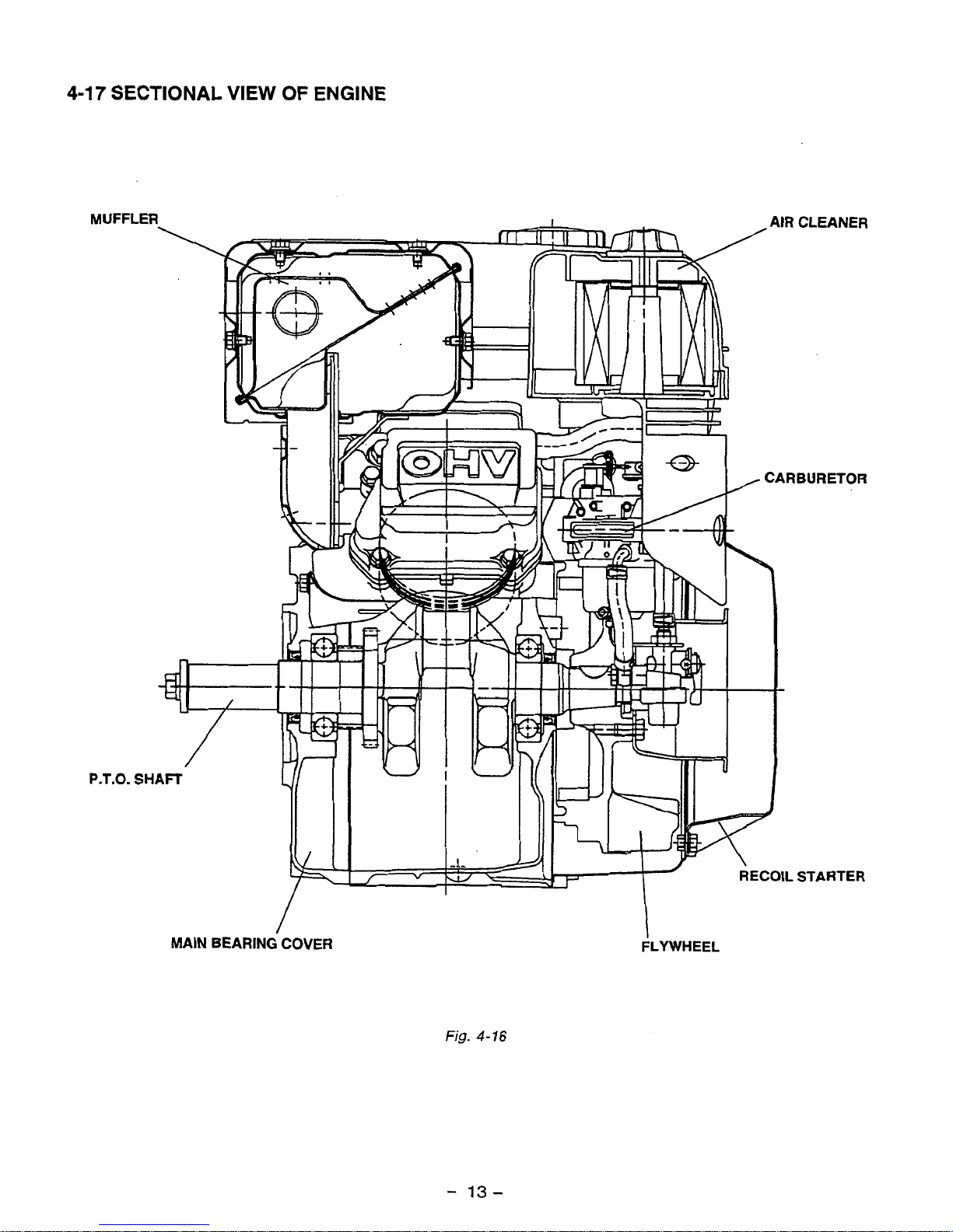
4-17
SECTIONAL VIEW
OF
ENGINE
MUFF
P.T.O.
MAIN
BEARING
COVER
Fig.
4-16
FLYWHEEL
-
13-
Page 17
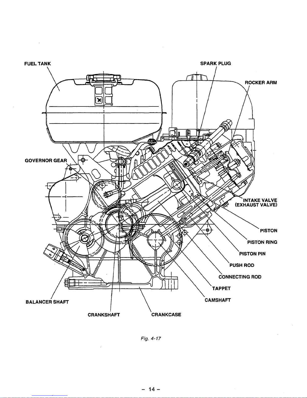
FUEL TANK SPARK PLUG
I
BALANCER SHAFT
\
CRANKSHAFT CRANKCASE
Fig.
4-17
CAMSHAFT
-
14-
Page 18
5.
DISASSEMBLY AND REASSEMBLY
5-1
PREPARATIONS
AND
SUGGESTIONS
1)
When disassembling the engine, memorize the locations
of
individual parts
so
that they can be
reassembled correctly.
If
you are uncertain
of
identifying some parts, it
is
suggested that tags be
attached
to
them.
2)
Have boxes ready to keep disassembled parts by group.
3)
To
prevent losing and mispfacing, temporarily assemble each group
of
disassembled parts.
4)
Carefully handle disassembled parts, and clean them with washing oil
if
necessary.
5)
Use the correct
tools
in the correct way.
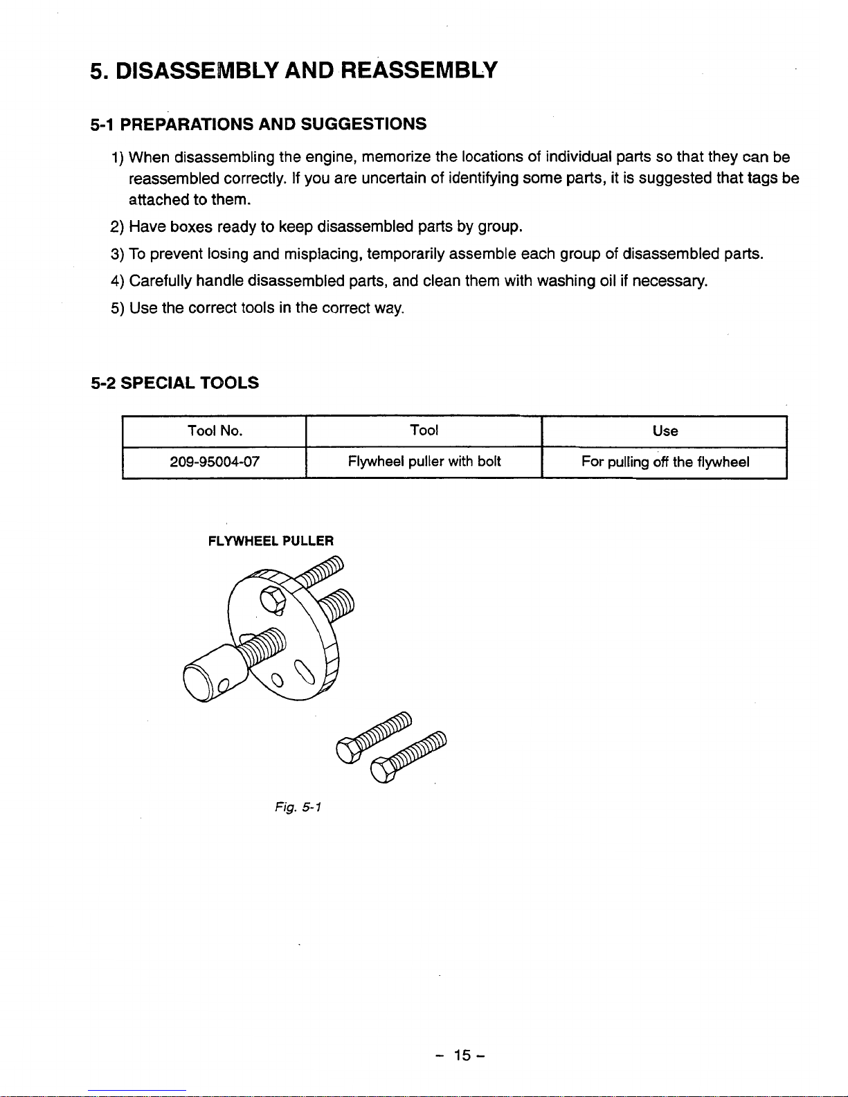
5-2
SPECIAL TOOLS
Tool
No.
Use
Tool
209-95004-07
For pulling
off
the flywheel Flywheel puller
with
bolt
FLYWHEEL
PULLER
-
15-
Page 19
5-3
DISASSEMBLY
PROCEDURES
fi
Step
Fasteners
Remarks
and
procedures
Parts
to remove
Engine oil drain
(2)
To
discharge oil quickly, remove
(1)
Remove
oil drain plug
and
drain
1
oil.
oil gauge.
OIL LEVEL
GASKET
I
OIL
DRAIN
PLUG
GAUGE
Fig.
5-2
-
16-
Page 20
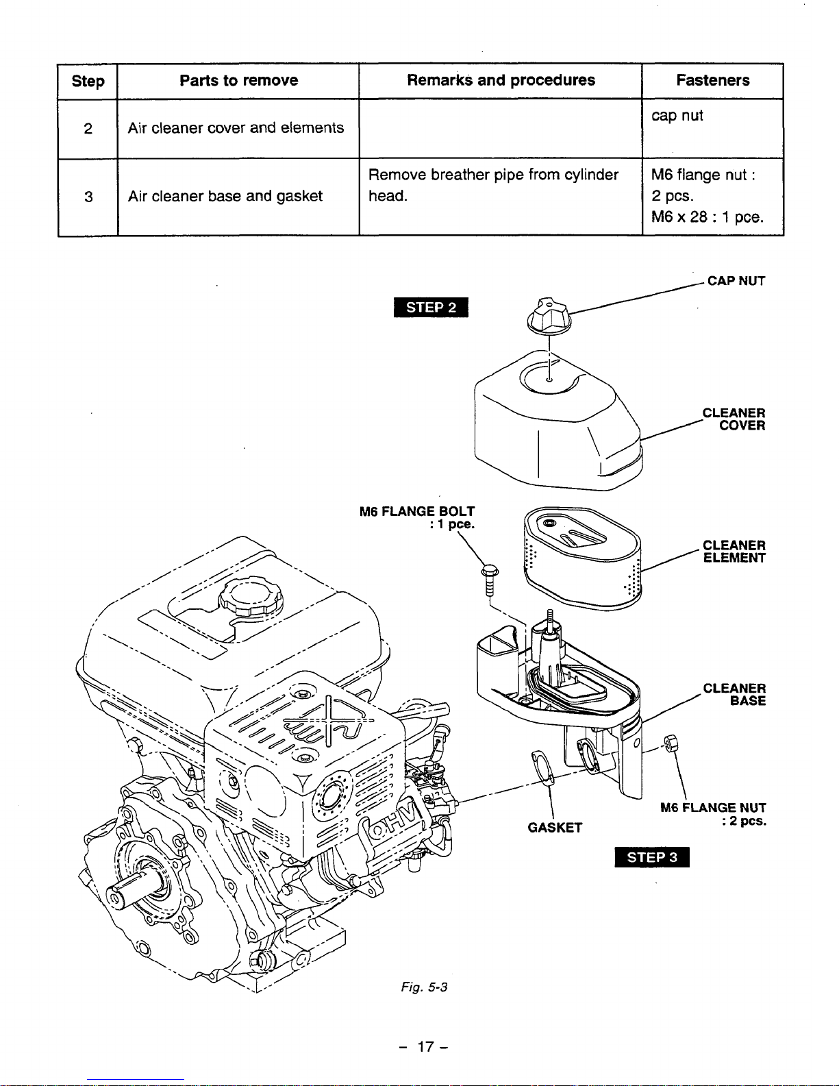
Step
2
3
Parts
Air cleaner cover and elements
Air cleaner base and gasket
to remove
Remarks and procedures
Remove breather
head.
pipe
from
cylinder
v
Fasteners
cap
nut
M6
flange nut
2
pcs.
M6
x
28
:
1
CAP
:
pce.
NUT
fig.
-
17-
5-3
Page 21
Step
4
Parts
to
remove
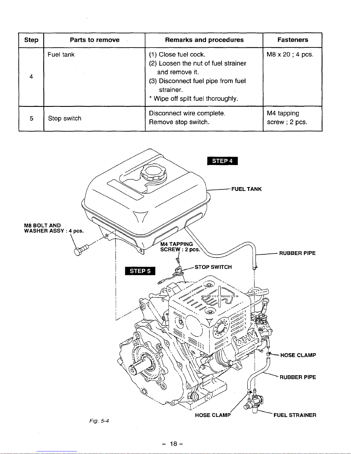
Fuel tank
.r
Stop
switch
M8
BOLT
AND
WASHER
ASSY
:
Remarks and procedures
(1)
Close fuel cock.
(2)
Loosen the
nut
of
fuel strainer
and
remove it.
(3)
Disconnect fuel pipe from
fuel
strainer.
*
Wipe
off
spilt
fuel thoroughly.
Disconnect wire complete.
Fasteners
M8 x 20
;
4
pcs.
Remove
stop switch.
I
screw
;
2
pcs.
RUBBER
PIPE
Fig.
5-4
-
18-
Page 22
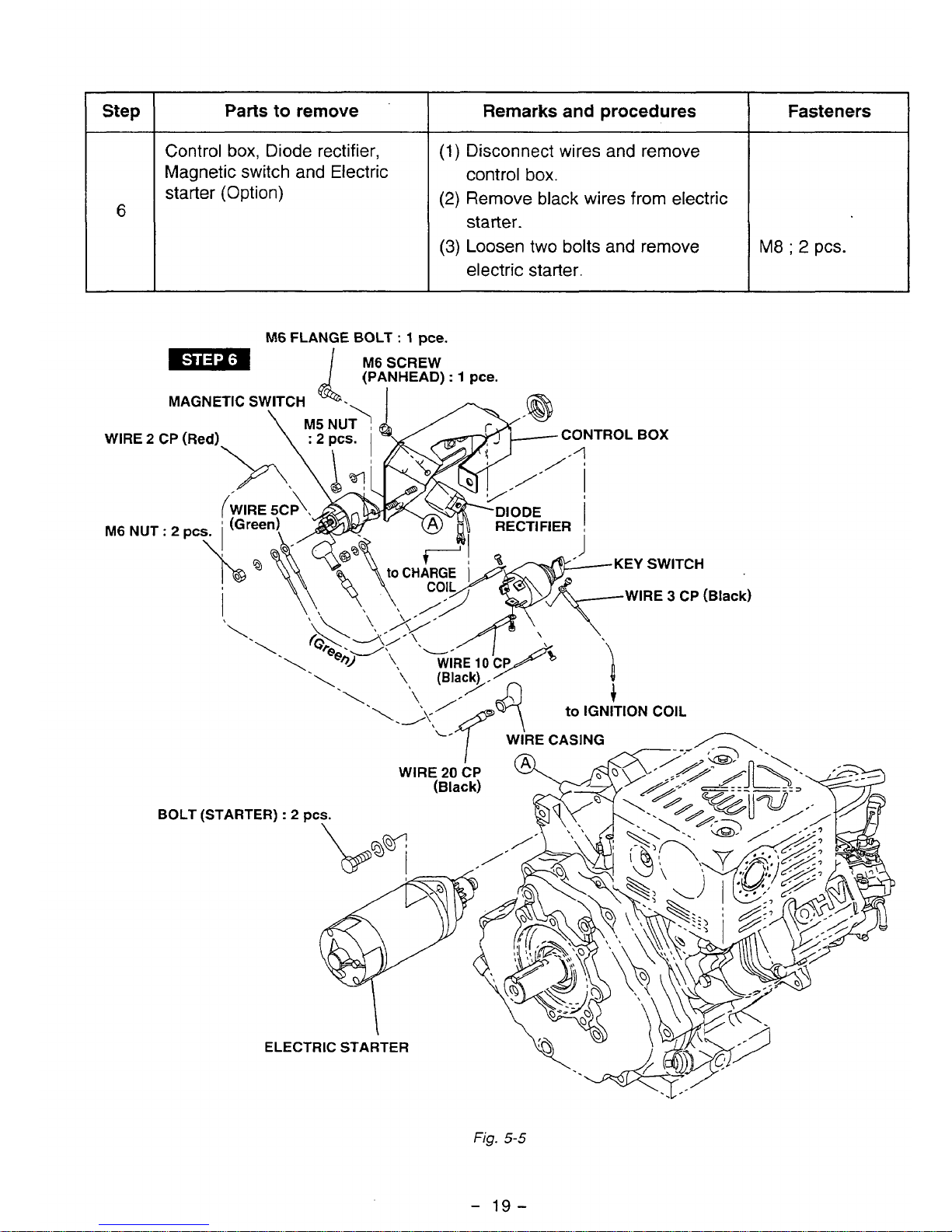
Parts to remove
Control
box,
Diode rectifier,
Magnetic switch
and
Electric
starter (Option)
Remarks and procedures
(1)
Disconnect wires
and
remove
(2)
Remove
black
wires from electric
(3)
Loosen
two
bolts and remove
control
box.
starter.
electric starter.
Fasteners
I
M8
;
2
pcs.
WIRE
2
M6
NU1
M6
FLANGE BOLT
:
1
me.
1
M6
SCREW
(PANHEAD)
:
1
pce.
Fig.
5-5
-
19-
Page 23
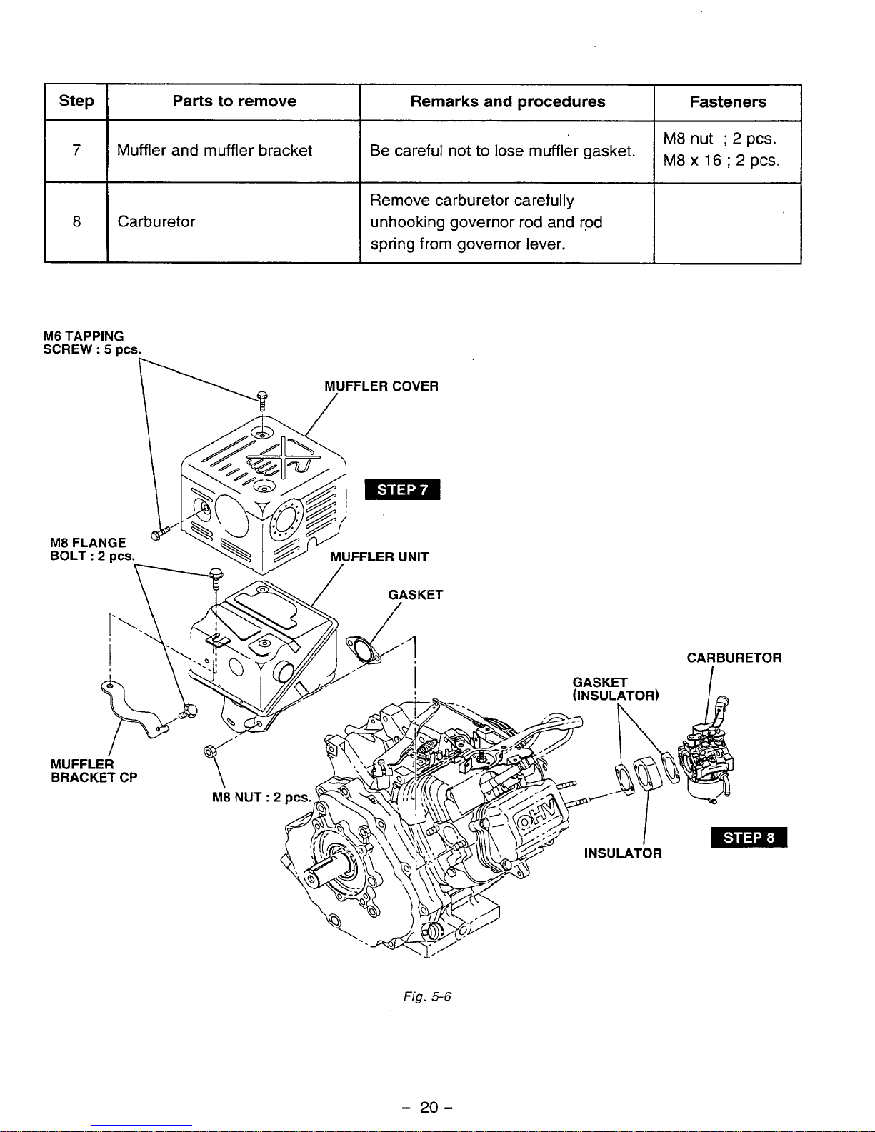
Step
Fasteners
Remarks
and
procedures
Parts
to
remove
7
Muffler and muffler bracket Be careful not
to
lose muffler gasket.
M8
nut
;
2
pes.
M8
x
16
;
2
pcs.
Remove carburetor carefully
spring from governor lever.
8
unhooking governor rod and rod
Carburetor
M6
TAPPING
SCREW
:
5
DCS.
M8
FLANGE
FFLER
UNIT
A
Fig.
5-6
-
20-
Page 24

Parts
to
remove
I
Remarks and procedures
(1
)
Unhook
governor spring from
governor lever.
Mark the hole
on
which the
governor spring
is
hooked.
governor lever.
~~~~~
(2)
Loosen the
bolt
and
remove
GOVERNOR LEVER
GOVERNOR
ROD
GOVERNOR SPRING
ROD
SPRING
M6
BOLT AND
WASHER
AY : 1
pce.
j
Fasteners
M6
bolt
Fig.
5-7
-
21
-
Page 25

Step
Fasteners
Remarks
and
procedures
Parts
to remove
Recoil
starter
10
M6
x
8
;
4
pcs.
(Pulley
cover
;
type
DS
and
type
BS)
11
M6
x
12
;
5
pcs..
Blower housing
M6
FLANGE BOLT
:
4
pcs.
\
M6
FLANGE
BOLT
BLOWER
HOUSING
CP
/
PULLEY
COVER
CP
(type
WBS)
Fig.
5-8
-
22-
Page 26

Step.
12
Parts to remove
I
Remarks and procedures
I
Fasteners
Ignition coil
I
(1)
Remove spark plug cap from
I
M6
x
25
;
2
pcs.
spark plug.
crankcase.
(2)
Remove ignition coil
from
13
M8
BOLT
:
3
pes.
(Except type
DS,BS)
\
Flywheel
(1)
Remove the starting pulley.
(2)
Remove nut from crankshaft.
M8
x
12 ; 3
pcs.
(See Fig.
5-1
1
.)
(4)
Remove the key from crankshaft.
flywheel puller. (See
Fig.
5-10.)
(3)
Remove flywheel using the
spring washer
(See Fig.
5-9.)
M18
nut, washer,
SPARK PLUG CAP
1
\
"STARTING PULLEY
I
WOODRUFF
KE
M6
BOLT AND
WASHER
AY : 2
pcs.
/
I
IGNITION
COIL
CP
Fig.
5-12
fig.
5-10
-
23-
Fig.
5-
7
7
Page 27

Step
A
Fasteners
Remarks
and
procedures
Parts
to
remove
14
M6
x
20 ; 2
pcs. Remove the charge coil.
Charge coil (Option)
1
15
1
Cylinder baffle
M6
x
8
;
4
pcs.
16
I
Spark
plug
1
NGK ; BPGES
CYLINDER BAFFLE
1
with
SPEED CONTROL
"a&)
M6
FLANGE BOLT
:
2
pcs.
"
M6
SCREW
(PANHEAD) : 1
pce.
M6
FLANGE
BOLT : 2
pcs.
Fig.
5-13
-
24-
Page 28

Parts
to
remove
I
Remarks and procedures
I
Fasteners
I
r
171
Rocker cover
Remove rocker cover and gasket
from cylinder head.
M6
x
25
;
4
pcs.
I
18
Rocker arm and push rod
(1)
Loosen nut and pivot
on
rocker
(2)
Remove push rods from cylinder.
arm.
Remove cylinder head and gasket
from crankcase.
MI0
x
65
;
4
pcs.
19
Cylinder
head
ROCKER
COVER
CP
-
CYLINDER
HEAD
FLANGE
BOLT
:
2
pcs.
A
\
/-
’*
\
/-
\
\
\
\
L
/-
/-
/-
Fig.
5-
14
-
25-
Page 29

Step
20
Parts
to
remove
intake and exhaust valves
Remarks and procedures
(1)
Press down spring retainer, take
out collet valve, and then remove
spring retainer and valve spring.
(2)
Remove intake and exhaust
valves from cylinder head..
Clean carbon and
gum
deposit from
the valves, valve seats,
ports
and
guides.
Inspect valves, valve seats and
guides.
Fasteners
INTAKE VAL
EXHAUST VAL COLLET VALVE
VALVE
SPRING
VALVE
GUIDE
u
Fig.
5-15
/-".
I
/"-
Fig.
5-
16
-
26-
Page 30

Step
Fasteners
Remarks
and
procedures
Parts to remove
Main bearing
cover
M8
Crr)x40;5
pcs.
Be
careful
not
to damage
the
oil seal.
21
M8
(12T)X40
;
Use
a
soft
hammer
and
evenly
tap
around outer surface
of
cover.
2P-
Fig.
5-
17
M8BOLT (12T) : 2
pcs.
Fig.
5-
18
Page 31

Step
Fasteners
Parts
to
remove Remarks
and
procedures
I
i?
22
Camshaft and tappets
Be careful not to damage camshaft
and tappets.
Position piston at top dead center
and remove balancer.
23
Balancer
I
Fig-
5-79
Fig.
5-20
-
28-
,-
Page 32

Step
24
25
Parts
to
remove
Connecting rod and piston
Piston and piston pin
Remarks and procedures
(1
)
Remove connecting rod bolts and
(2)
Turn crankshaft until piston
connecting rod cap.
comes to top dead center, push
out connecting rod and piston
assembly through top of cylinder.
*Scrape
off
all carbon deposits that
might interfere with removal
of
piston from upper end
of
cylinder.
(1
)
Remove clips and piston pin to
remove connecting rod
from
piston.
(2)
Remove piston rings from piston.
*Be
careful not to give damages to
piston and connecting rod.
Be careful not to break rings
by
spreading
too
much or twisting.
Fasteners
M8
x
40
;
2
pcs
CLIP
PISTON
PIN
\
\
PISYON
RINGS
PISTON
Fig.
5-21
-
29-
Page 33

Step
26
Parts to remove
Crankshaft
Remarks and procedures
.Tap
lightly
on
flywheel
end
of
crankshaft
to
remove from
crankcase.
I
w
Fig.
5-22
__1
Fasteners
CRANKSHAFT
-
Fig.
5-23
-
30-
Page 34

5-4
REASSEMBLY
PROCEDURES
0
PRECAUTIONS FOR REASSEMBLY
1)
Clean parts thoroughly before reassembly.
Pay most attention
to
cleanliness
of
piston, cylinder, crankshaft, connecting rod and bearings.
2)
Scrape
off
all
carbon deposits from cylinder head, piston top and piston ring grooves.
3)
Check lip of
oil
seals. Replace oil seal
if
the lip is damaged. Apply oil to the lip before reassembly.
4)
Replace all the gaskets with new ones.
5)
Replace keys, pins, bolts, nuts, etc.,
if
necessary.
6)
Torque bolts and nuts to specification referring
to
the
"TORQUE
SPECIFICATIONS".
7)
Apply oil to rotating and sliding portions.
8)
Check and adjust clearances and end plays where specified in this manual.
5-4-1
CRANKSHAFT
(1)
Install crankshaft on crankcase wrapping the
key-way with polyvinyl tape
to
avoid damage
to oil seal.
(2)
Install
woodruff
key for flywheel
on
crankshaft.
Fig.
5-24
5-4-2
PtSTON
AND
PISTON
RINGS
(1)
Install oil ring first, then second ring and top
ring.
Spread ring only far enough to
slip
over pis-
ton and into correct groove. Use care not to
distort ring.
Install second ring with punched mark beside
the
gap
face upward. (See Fig.
5-27)
OPEN
ENDS
OF
PISTON
RING
I
I
Fig.
5-25
-
31
-
Page 35

r
I
L
I
I
Fig.
5-26
5-4-3
PISTON AND CONNECTING
ROD
The direction of piston
on
connecting rod is not
specified.
Apply oil to the small end
of
connecting rod be-
fore assembling piston and piston pin.
Use
clips
on
the both side
of
the piston
pin
to
se-
cure piston pin
in
position.
MARK
“1“
\
Fig.
5-27
Fig.
5-28
-
32-
Page 36

(2)
Install piston and connecting
rod
assembly
into cylinder.
Use a piston ring compressor to hold piston
rings.
The
"FAN"
mark
of
the connecting
rod
is to
face flywheel side when assembled.
Note:
(1)
Apply enough oil
to
piston
rings,
con-
necting
rod
bearings and cylinder
bore before
assembly.
(2)
Set
gaps of the piston rings
90
de-
grees apart from
each
other before
assembly.
5-4-4
CONNECTING
ROD
(1)
Turn
crankshaft to
bottom
dead center, lightly
tap top
of
the piston until large end
of
the rod
meet crank pin.
(2)
Install connecting rod cap to connecting rod
matching alignment marks.
Torque connecting rod bolts
to
specification.
M8
x
40
mm
connecting rod bolt
:
2
pcs.
Tightening torque
:
22.1
-
27.0
N
.m
(225
-
275
kg
mcm)
(16.3
-
19.9
ftmlb.)
Fig.
5-29
i/"-
SECOND
RING
Fig.
5-30
ALIGNMENT
GARKS
Fig.
5-31
(3)
Check for free movement
of
connecting rod
by
turning crankshaft slowly.
-
33-
Page 37

Install balancer shaft to crankcase aligning match-
ing mark
of
balancer gear
and
crank gear as
shown in the illustration.
CAUTION
:
Incorrect timing
of
the
gears
will
cause
malfunction of
the
engine and
may
re-
sults
in damage
due
to interference
of
the
parts.
~~~
CRANKSHFT
GEAR
~~
5-4-6
TAPPETS
AND
CAMSHAFT
(1)
Oil
the tappets and install them.
Push in fully
to
avoid damage during camshaft installation.
(2)
Lubricate bearing surfaces
of
camshaft.
TIMING
MARKS
Fig.
5-32
Align the timing mark on crankshaft gear with the timing mark on camshaft and install camshaft in the
crankcase. (See Fig.
5-32)
Incorrect
valve
timing
will
cause mal-
function
of
the
engine.
5-4-7
ADJUST CRANKSHAFT AND CAMSHAFT END
PLAY
(1)
Adjust end play to the specified values using the proper spacer.
The proper spacer may be determined following manner.
DEPTH
GAUGE
MAIN
BEARING COVER
7
I
0'
'0
1
t
I
CRANKCASE
Fig.
5-33
-
34-
Fig.
5-34
Page 38

5-4-7-1
CRANKSHAFT
END
PLAY
(For
type
D
and
type
B)
1) Measure the depth “Al” (From the mating surface to the inner race
of
the ball bearing.)
2) Measure the height “Bl” (From the mating surface to the crank gear.)
(A1
+0.35)-81=
SIDE CLEARANCE (mm)
(SIDE CLEARANCE)-0.2
mm
=THICKNESS
OF
CRANKSHAFT SHIM
(mm)
(A1 +O.O14)-Bl= SIDE CLEARANCE (in.)
(SIDE CLEARANCE)-0.008
in.=
THICKNESS
OF
CRANKSHAFT SHIM (in.)
Following are available spacer
shims.
CRANKSHAFT
T=
0.6
mm
(0.024
in.)
SPACER
SHIMS
T=
0.8
mrn
(0.031
in.)
T=
1.0
rnrn
(0.039
in.)
.
Table.
5-1
5-4-7-2
CAMSHAFT
END
PLAY
(For
type
D and
type
B)
1) Measure the depth
“A2”
(From the mating surface to the inner race
of
the ball bearing.)
2)
Measure the height “82” (From the mating
surface
to the cam gear inner boss.)
(A2+0.35)-62=
SIDE
CLEARANCE
(mm)
(SIDE CLEARANCE)-0.2 mm = THICKNESS
OF
CAMSHAFT
SHIM
(mm)
(A2+0.014)-B2= SIDE CLEARANCE (in.)
(SIDE CLEARANCE)-0.008 in.= THICKNESS
OF
CAMSHAFT SHIM (in.)
Following are available spacer shims.
CAMSHAFT
For
type
D
For
type
B
T=
0.6
mm
(0.024
in.)
T=
1.0
mrn
(0.039
in.)
T=
0.8
mm
(0.031
in.)
T=
0.8
mm
(0.031
in.)
T=
0.7
mm
(0.028
in.)
SPACER
SHIMS
T=
0.6
mm
(0.024
in.)
Table.
5-2
-
35-
Page 39

(2)
Lubricate the oil seal and bearing surfaces. Add a light film
of
oil on main bearing cover face to hold
the gasket in place. Place spacers chosen at procedure
(1)
on crankshaft and camshaft.
A
Use an oil seal guide when installing main bearing cover to avoid damaging the seal.
Tap the cover into place with a soft hammer.
NOTE
;
Be
sure
to
use
two
M8
(12T)'BOLTS and
WASHERS
in
two
locations just-the root of cylinder to fasten the
main bearing cover
to
crankcase. For other five locations,
use
M8
(TT)
BOLT
8,
WASHER
ASSY.
\
Mi
BOLT
(7T)
AND
WASHER
AY : 5
pcs.
M8 BOLT
(12T)
:
2
pcs.
Fig.
5-35
5-4-8
CYLINDER HEAD
(1)
Clean carbon and gum deposits from the valves, seats, ports and guides. Inspect valves, valve seats
and valve guides.
(2)
Replace valves that are badly burned, pitted or warped.
(3)
When installing valves in cylinder head, oil the valve stems and insert them into valve guide.
Then place cylinder head on fiat table, install valve spring and spring retainer.
-
36-
Page 40

(4)
Valve guides should be replaced when valve stem clearance exceeds specifications (See “SERVICE
DATA).
Draw valve guides out and press new guides in.
Refer to
“SERVICE
DATA for clearance specifications.
After replacing valves and guides,
lap
valves in place until a uniform ring shows around the face of
the valve. Clean valves and wash cylinder head thoroughly.
(5)
Install cylinder head to cylinder with new head gasket.
Tighten four flange bolts evenly
in
three steps by the following tightening torque:
Cylinder head
MI0
x
65
mm bolt
:
4
pcs.
I~
Tightening
torque
I
1
st
step
I
2
nd step
I
Final Step
I
r
~~
9.8
N
-m
(24.6-30.4
ft . Ib.)
(1
4.5
f?
-
Ib.)
(7.2
ft
-Ib.)
(340-420
kg
-
cm)
(200
kg
scrn)
(100
kg
mcm)
33.3-41.2
N
-
m
19.6
N
-m
I
I
I
I
5-4-9
ROCKER
ARMS
AND
PUSH
RODS
(1)
Insert push rods into crankcase. Put
push
rod tip in the hollow of tappet top.
(2)
Apply oil
to
rocker
arms
and assemble them to cylinder head using pivot
and
nut.
pcs.
Fig.
5-36
-
37-
Page 41

5-4-10
VALVE
CLEARANCE
ADJUSTMENT
Note:
Temporally fit the
flywheel
in position for
easy
operation.
(1)
Position piston at top dead center
of
compres-
sion stroke by matching the mark
"T"
of
fly-
wheel
with the thread hole
(@)
of
crankcase.
(2)
Loosen the nut
on
rocker arm and turn the pivot
to adjust the clearance between rocker arm
and valve stem end.
Tighten the nut on rocker arm.
-
Valve clearance : 0.085
-
0.11
5
mm
(0.0034 - 0.0045
in.)
r
Note:
Check and adjust valve clearance while
engine is
cold.
Check
operation
of
valves
by
turning
crankshaft. Then recheck the valve clear-
ance.
(3)
Install rocker cover and gasket.
Rocker cover
M6
x
25
mm bolt
: 4 pcs.
5-4-11
SPARK
PLUG
Install spark plug
to
cylinder head.
Spark
plug
:
NGK
BPGES
I
Tightening torque
1
I
New
spark
plug
1
Retightening
1
11.8
-
14.7
N
m
(230
-
270
kg
.
cm)
(1
20
-
150
kg
-
cm)
22.6
-
26.5
N
-
m
(8.7 - 10.9
ft
.
Ib.)
(1
6.6
-
19.5
ft
Ib.)
I
1
'THREAD
HOLE
(01
Fig.
5-37
A
Fig.
5-38
-
38-
Page 42

5-4-1
2
CY
LlNDER
BAFFLE
Install cylinder baffle
to
cylinder head.
M6
x 8 mm flange bolt
: 4 pcs.
5-4-13 FLYWHEEL
MAGNETO
(1)
Install charge
coil
to crankcase. (Option)
Clamp
coil
wire to crankcase.
Note:
Be careful not to pinch coil wire between
charge coil and crankcase.
(2)
Put woodruff key in keyway
of
crankshaft. Wipe
off oil and grease thoroughly from tapered portion of crankshaft and flywheel center hole.
(3)
Install
flywheel
to crankshaft.
Tighten flywheel nut with spring washer and
washer.
Tightening torque
:
78.4
-
98.0
N
-m
(800 - 1000
kg cm)
(58.0
-
72.5
ft.lb.1
(4)
Install starting pulley to flywheel.
M8
x
12
mm bolt
:
3
pcs.
Tightening torque
:
6.9 - 8.8
N
m
(70 - 90
kg
-cm)
(5.1
-
6.5
ft'lb.)
5-4-14
IGNITION
COIL
Install ignition
coil
to
crankcase.
Adjust air gap between ignition coil and flywheel
using a thickness gauge and tighten bolts.
M6 x 25
mm
bolt
:
2
pcs.
I
1
Air
gap
:
0.3
-
0.5
mrn
(0.012
-
0.020
in.)
Fig.
5-39
~~
Fig.
5-40
-
39-
Page 43

5-4-15
BLOWER
HOUSING
AND
RECOIL
STARTER
(1)
Attach blower housing
to
crankcase. Tighten
five flange bolts.
M6 x 12
mm flange bolt
:
5
pcs.
Insert the high tension cord from the ignition
coil into the notch
of
the blower housing
so
that not to pinch the cord.
(2)
Install recoil starter
to
blower housing.
M6
x 8 rnm flange bolt
: 4 pcs.
Note:
Be
careful
of
pulling direction
of
starter
rope.
5-4-16
GOVERNOR, SPEED CONTROL
SYSTEM AND CARBURETOR
Install governor lever to governor shaft.
Tighten locking bolt temporarily.
Install speed control lever to cylinder baffle,
friction washer, self lock nut, etc.
as
shown in
illustration.
Hook
governor spring to proper holes of gov-
ernor lever and speed control lever.
(See Fig.
5-42
and below.)
I
Hooking
position
Fig.5-42
I
Rated
3000
rprn
(50
Hz)
applications"]-
5-C
I
~~
GOVERNOR LEVER GOVERNOR
ROD
STOP
PLATE
WASHER
CYLINDER
BAFFLE
1
I
Rated
3600
rpm
(60
Hz)
applications
I
4-C
I
'(4)
Install insulator and gaskets
for
carburetor to
cylinder
head.
Fig.
5-41
-
40-
Page 44

(5)
Install carburetor to cylinder head hooking governor rod to governor lever and throttle lever
of
carbu-
retor. Hook rod spring
over
governor rod.
(6)
Attach air cleaner base to carburetor. Tighten
two
flange nuts and a
bolt.
Connect breather pipe from
rocker cover to cleaner base.
VERNORGEAR
GOVERNOR
ROD
GOVERNOR SPRlN
FULL
CLOSE
PEED
SELF LOCK NU
ADJUSTING
SCRE
CARBURET0
Fig.
5-42
-
41
-
Page 45

(7)
Adjust governor system.
(a) Turn the speed control lever all the way
toward the high speed position and fix it by
tightening self lock nut.
(b) Check that governor lever is pulled by gov-
ernor spring and carburetor throttle valve
is fully open.
(c) Turn governor shaft counterclockwise all
the way using a screw driver, and tighten
lock bolt to secure the lever on the shaft.
(d)
Loosen the self Jock nut to allow the speed
control lever to move freely.
5-4-1 7 MUFFLER
GOVERNOR
Fig.
5-43
(1)
Install muffler bracket to cylinder head.
M8
x
16
mm bolt
: 2 pcs.
(2)
Install muffler-to muffler bracket.
M8
flange nut
:
2
pcs.
(3)
Install muffler cover.
M6
tapping screw
: 5 pcs.
5-4-18
STOP
SWITCH
(1)
Install stop switch to blower housing.
(2)
Connect wires referring to the wiring diagram.
5-4-19 ELECTRIC STARTER
AND
CONTROL
BOX
CP (Optional equipment)
(1)
Install electric starter to crankcase.
(2)
Install control
box
cp (include magnetic switch, diode rectifier and key switch) to crankcase.
(3)
Connect wires referring to the wiring diagram.
5-4-20
FUEL TANK
(1)
Install fuel tank to crankcase.
M8
x
20
mm bolt
:
4
pcs.
(2)
Connect fuel strainer and fuel inlet of carburetor with the fuel hose. Be sure to clamp securely.
5-4-21
AIR
CLEANER
Install air cleaner element and cleaner cover
-
End of the reassembly
-
-
42-
Page 46

5-5
BREAK-IN OPERATION
An engine that has been completely overhauled by being fitted with a new piston, rings, valves and
connecting rod should be thoroughly
RUN-IN
before being put back into service.
Good bearing surfaces and running clearances between the various parts can only be established
by
operating the engine under reduced speed and loads for a short period of time.
While the engine is being tested, check for oil leaks.
Make final carburetor adjustment and regulate the engine operating speed.
Step
10
min.
3,600
rpm
No
Load
Step
3
10
min.
3,000
rpm
No
Load
Step 2
10
min.
2,500
rpm
No
Load
Step
1
Time Engine Speed
Load
Step
4
3,600
rpm
30
min.
EH36
7.0
kW
(9.5
HP)
EH41
6.3
kW
(8.5
HP) EH36
3.5
kW
(4.8 HP)
EH41
3.2 kW
(4.3 HP)
*
Step
5
60
min.
3,600
rpm
Table.
5-2
6.
MAGNETO
6-1
FLYWHEEL
MAGNETO
The ignition system
of
the EH36/EH41 is a pointless flywheel magneto with automatic advancing char-
acteristic.
Being different from the breaker point type ignition system, this system is completely free from such
troubles as starting-up failure due to dirty, burnt or corroded point surface.
The electronic automatic advancing ensures extremely easy starts and stable high performance at oper-
ating speed
by
advancing the ignition timing to the most suitable point.
6-2
BASIC
THEORY
(1)
Revolution of the flywheel generates electricity
on
the primary side of the ignition coil, and the base
current
11
flows
to
the power transistor.
Current
11
turns the power transistor
“ON”
and the electric current
I2
flows.
-
43-
Page 47

(2)
At
lower engine revolution, when the flywheel reached the ignition point the low speed ignition timing
control circuit operates to run the base current
I3
to turn the signal transistor
A
“ON”
allowing the
current
11
to bypass as current
14.
At this moment the power transistor turns
“OFF”
and the current h is abruptly shut resulting in the
high voltage generated in the secondary coil which produces sparks at the spark plug.
(3)
At higher engine revoluti.on, the advancing control circuit operates at the ignition timing to run the
base current
I5
to turn the signal transistor
E3
“ON”
allowing the current
11
to bypass as current
Is.
At this moment the power transistor turns
“OFF”
and the current h is abruptly shut resulting in the
high voltage generated in the secondary coil which produces sparks at the spark plug.
The operating timing
of
the advancing control circuit advances in accordance with the increase
of
engine speed resulting in the advancing
of
ignition timing
as
shown in Fig. 6-l(b).
Fig.
6-7
(a)
ELECTRONIC ADVANCING
FLYWHEEL
(B.T.D.c.)
MAGNETO
SYSTEM
f
STEP
ADVANCING
I
I
I
I
500
1000
2000
3000
(r.p.m.)
ENGINE REVOLUTION
,“-
Fig.
6-1
(b)
-
44-
Page 48

6-3
WIRING
DIAGRAM
0
STANDARD
Ignition
Coil
Connector Stop Switch
Spark
plug
///
Flywheel
Fig.
6-2
0
ENGINE
WITH
ELECTRIC STARTER
Electric starter Magnetic Switch
Fig.
6-3
-
45-
Page 49

7.
AUTOMATIC
DECOMPRESSION
SYSTEM
EH36,
41
engines are employing the automatic decompression system as a standard feature.
This enables easy and light start of the engine.
The automatic decompression system releases the compression of the engine by lifting up the exhaust
valve at the cranking. Following are the explanation using type
“D”
engine as a sample how the system
works. The components of the systems are different for the type
“D”
and
“B
engines, however, the
pinciple
of
the function
is
same.
At the end of the compression process, the release lever lifts up the tappet which in turns opens
up
the
exhaust valve slightly to release the compression. The release lever has
a
flyweight on its end and
another end of the lever is a crescent cam.
When the engine is cranked, the cresent cam projects the camshaft cam profile and lifts up the tappet
because the gravity force on the weight is larger than the centrifugal force on the weight.
CRESCENT CAM
EXHAUST CAM
LEVER
‘1
CAMSHAFT
Fig.
7-1
When the crank speed reaches
up
to a certain revolution, the cresent cam is retracted into the camshaft
cam profile because the centrifugal force applied onto the flyweight becomes larger than the gravity force
and the weight and is shifted to the position shown in the illustration.
FLYWEIGHT
CRESCENT
CAM
EXHAUST
CAM
LEVER
-
46-
Page 50

8.
CARBURETOR
8-1
OPERATION
AND
CONSTRUCTION
8-1
-1
FLOAT
SYSTEM
The float chamber is located below the carburetor body and, with
a
float
and
a
needle valve,
maintains a constant fuel level during engine
op-
eration.
The fuel flows from the fuel tank into the float
chamber through needle valve. When the fuel
rises to
a
specific level, the float rises, and when
its buoyancy and fuel pressure are balanced, the
needle valve closes to shut
off
the fuel, thereby
keeping the fuel at the predetermined level.
PILOT OUTLET
1
"""_
"_
'"""_ESIX
Fl
Fig.
8-1
PILOT
JET
""_
""""""
II
"
-
"
/
-OAT
-\
MAIN
JET
Fig.
8-2
-
47-
Page 51

8-1-2
PILOT SYSTEM
n
The pilot system feeds the fuel to the engine during idling and low-speed operation. The fuel is fed
through the main jet
to
the pilot jet, where it is metered, and mixed with the air metered by the pilot air jet.
The fuel-air mixture is fed to the engine through the pilot outlet and the by-pass. At idling speed, the fuel
is mainly fed from the pilot outlet.
8-1-3
MAIN
SYSTEM
The main system feeds the fuel to the engine at medium and high-speed operation. The fuel is metered
by the main jet and fed to the main nozzle. The air metered by the main air jet is mixed with the fuel
through the bleed holes in the main nozzle, and the mixture
is
atomized out of the main bore. It is mixed
again with the air taken through the air cleaner into an optimum fuel-air mixture, which
is
supplied to the
engine.
8-1
-4
CHOKE
The choke is used for easy start when engine is cold. When the starter is operated with a closed choke,
the negative pressure applied to the main nozzle increases and draws much fuel accordingly
;
thus
easily start up the engine.
8-2
DISASSEMBLY AND REASSEMBLY
Apart from mechanical failures, most of carburetor troubles are caused by an incorrect mixing
ratio, which may arise mainly due to a clogged up
air
or
fuel passage in jets, or fuel level variations.
In order to assure proper flow of air and fuel, the
carburetor must be kept clean at all times. The
carburetor disassembly and reassembly procedures are
as
follows.
8-2-1
THROTTLE SYSTEM
(1
)
The spring
(4)
can be taken out by removing
the throttle stop screw
(5).
(2)
Remove the Phillips screw
(1)
and throttle valve
'
(2),
and pull out the throttle shaft
(3).
*Exercise care not to damage throttle valve ends.
12311
19
21
13
18d
l2
-
Fig.
8-3
-
48-
Page 52

8-2-2
CHOKE SYSTEM
(1)
Remove the Phillips screw
(6)
and choke valve
(7),
and
pull
out the choke shaft
(8).
(2)
When reassembling the choke shaft, make sure that the cutout in the choke valve faces the pilot air
jet. Meantime, when reassembling set the rings
(9)
and
(1
0)
at the right position.
8-2-3
PILOT
SYSTEM
(1)
Remove the pilot jet
(ll),
using correct tool to avoid damage to it.
(2)
Reassembly
Tighten the pilot jet securely. Otherwise, the fuel may leak, causing engine malfunction.
8-2-4
MAIN
SYSTEM
(1)
Remove the bolt
(12)
and take out float chamber body
(13).
(2)
From the body
(14)
remove the main jet
(1
6)
and guide holder. And then remove the main nozzle
(1
5).
(3)
Reassembly
a) Fasten the main jet and main nozzle securely to the body. Otherwise, the fuel may become too rich
and cause engine malfunction.
b) The bolt
(12)
tightening torque is
90
kg-cm. Be sure to set the gasket
(1
9)
and washer
(18)
for
chamber
(1
3).
8-2-5
FLOAT
SYSTEM
(1)
Pull
out the float pin
(20)
and remove the float
(21)
and then remove the clip
(22)
and needle valve
(23).
If
the needle valve need
to
be replaced, replace it with rubber needle.
CAUTION
:
When cleaning the jets, use neither a
drill
nor a wire (because
of
possible damage
of
the
orifice
which
will adversely affect fuel
flow).
Be sure to
use
compressed air
to
blow
them
clean.
(2)
When removing the needle valve and float, gently tap the reverse side using the rod more slender
than the float pin and remove, since the float pin is calked to the carburetor body.
-
49-
Page 53

9.
STARTING
SYSTEM
9-1
RECOIL
STARTER
Trouble in the recoil starter rarely happens while it is in normal operation.
If the starter develops trouble or when it is lubricated, carry out in accordance with following disassembling and assembling procedures.
Tools ; Box
spanner (spanner)
Pliers
Screwdriver
Nippers
or
Knife
9-1-1
HOW
TO
DISASSEMBLE
(type
D)
(1)
Remove the recoil starter from engine.
(2)
Pull the starter knob to draw, out the starter
rope
by about
30
cm and tie a tentative knot
as show in Fig.
9-1.
(3)
Untie the knot inside the knob to remove the
knob.
(4)
Hold the starter case and the reel firmly with
your left hand and untie the tentative knot with
,
your right hand.
Continue to hold the case and the reel with
your left hand and hold the reel center with
your right hand, then loosen both hands alternately to allow the reel gradually
to
turn to the
arrow direction until the spring is completely
released.
(Do
this carefully to avoid dangers caused by
spring-back.)
7Y
STARTER ROPE
Fig.
9-
1
STARTERCASE
Direction
to
release
Fig.
9-2
-
so-
Page 54

(5)
Remove each part in accordance with Fig.
9-3
1.
Center screw
2.
Friction plate
3.
Friction spring
4.
Ratchet
5.
Ratchet spring
6.
Reel
Take out the reel slowly while turning
it
back
and forth gently, otherwise the spring may
es-
cape from the case which may invite danger.
(If
the spring escapes, put it in the housing by
following procedures shown in Fig.
9-8.)
Untie the starter rope knot at reel end and withdraw
it
to complete disassembling.
9-1-2
HOW
TO
REASSEMBLE
(D-Type)
(1)
Cut
off
a part
of
the reel shown in Fig.
9-4
with
a nippers or a knife
to
form a which is required
when pre-winding the spring.
(2)
Check that the spring
is
securely set in the
reel and form the spring end to measure
1
mm
to
2
mm for clearance between inner end of
the spring and the reel bushing edge
so
that
the hook catches securely as shown
in
Fig.
9-5.
The shape of spring inner end (approx.
10
cm
from the end) may be adjusted with
a
plier
if
necessary.
(3)
Apply a small amount of grease
to
the starter
shaft and to the spring.
STARTER
SHAFT
(Grease
is
to
be
applied)
Fig.
9-3
Fig.
9-4
Outer
end
of
spring
SPRING HOUSING
\
er
end
of
spring
Apply
grea
REEL
BUSHING
Fig.
9-5
-
51
-
Page 55

(4)
Pass the starter rope through the starter knob
and tie the rope end to make
a
tight overhand
knot as shown in Fig.
9-6.
Then put the knot
into the knob.
(5)
Pass the other end
of
the .rope from the starter
case to the reel and make
a
knot as illustrated
above, then put the rope end securely into the
rope housing in the reel.
(6)
Wind the starter rope by
1.5
turns in the arrow
direction as shown in Fig.9-7 to let the rope
out of the reel through the notch, then install
the reel securely in the starter case
so
that
the hook catches inner end of the spring.
(7) Hold the starter rope as shown in the Fig.9-7
and rotate the reel
6
tums by applying the force
directly
to
the reel notch. (pre-winding)
Hold
the reel securely to prevent it from reverse turn and pull the starter knob to stretch
the rope tight then release the
knob
slowly.
Reassemble the parts in reverse order of disassembling shown in Fig.
9-3.
Tighten the center screw securely.
*This concludes
disassembling/reassembling.
Be sure to check the following to make sure
of
it.
Puli
the rope
Fig.
9-6
STARTER
CASE
Strech rope them release
it
after
pre-wound
,"--
Fig.
9-7
-
52-
Page 56

9-1-3
CHECK
AFTER
REASSEMBLY
(1)
Pull the starter knob a few times to check
if
:
A.
The starter knob is too heavy to pull, check that each part has been assembled as specified.
8.
The ratchet fails to function, check that parts such as friction spring have been missing.
(2)
Pull out the starter knob to extend the rope to its extreme to see
if:
A.
The starter rope still remains in the rope slot in the reel, unwind the rope by 1 mm to 2 mm turns
as
the spring may be over-stressed.
B.
The starter rope
is
found weak to recoil or droops in halfway, apply grease
or
mobile oil to the
rotating part and to the friction parts.
If this persists, wind-up the spring by
1
mm to 2 mm
turns.
(In this case, check that the spring is not
over-stressed.)
C.
The spring escapes with a sound and the starter rope fails to spring back to its original position,
reassemble the starter from the beginning.
9-1-4
OTHER
GUIDES
(1)
When the spring escapes from the reel:
Make a ring having
a
rather small diameter
than spring housing using
a
thin wire.
Hook
the outer end
of
the spring onto a part
of
the ring and re-wind the spring into the wire
ring
as
shown in Fig.
9-8
then put
it
into the
housing.
Remove the ring slowly while holding down
the spring to avoid getting out
of
place.
The ring can easily be removed by prying it
with the tip of a screwdriver.
Refer to Fig.
9-5
for which way the spring must
be placed.
If the wire ring is not available, re-wind the
spring directly into the housing.
Fig.
9-8
(2)
When it is lubricated:
Lubricate the starter shaft and the spring with
a
grease
(If
possible, heat-resistant type is preferable)
or a mobile
oil
when the starter is being disassembled and prior to long term storage.
-
53-
Page 57

9-2
ELECTRIC STARTER
i".
I
NOTE;
1
For Electric starter operation, electric wiring should be connected among electric starter,
magnetic switch, key switch and battery as shown in the diagram.
Ignition Coil Unit
Black
I.
I
Green
I
"'
u
Electric starter Magnetic Switch
Fig.
9-9
wire
9-2-1
OPERATION AND FUNCTION
When key switch is turned
ON,
lower electric current
(M
-)
flows through coil
of
magnetic switch and the
coil is excited. The plunger
is
pulled and higher current
(S
-
)
flows
through electric starter.
When electric starter
is
operated, pinion gear
is
pushed
out
by means of centrifugal force of weight
located in the spline of armature shaft. The pinion gear is engaged with ring gear and flywheel and
crankshaft are rotated.
M
'*M
S
S
c
c
BAlTERY
ELECTRIC STARTER
KEY
SWITCH
I'
Fig.
9-70
-
54-
Page 58

9-2-2
COMPORNENT
PARTS
Fig.
9-11
-
55-
Page 59

The following three conditions must be fulfilled for satisfactory engine start.
1.
The cylinder filled with a proper fuel-air mixture.
2.
Good
compression in the cylinder.
3.
Good spark, properly timed, to ignite the mixture.
The engine cannot be started unless these three conditions are met. There are also other factors which
make engine start difficult,
e.
g., a heavy load on the engine when
it
is about to start at low speed, and a
high back pressure due to a long exhaust pipe.
The most common causes of engine troubles are given below
:
10-1
STARTtNG
DlFFtCULTtES
10-1
-1
FUEL
SYSTEM
(1)
No
gasoline in the fuel tank,
or
the fuel cock closed.
(2)
The carburetor is not choked 'sufficiently especially when the engine is
cold.
(3)
Water, dust or gum in the gasoline interfering the fuel flow to the carburetor.
(4)
Inferior grade gasoline
or
poor quality gasoline not vaporized enough to produce the correct fuel-air
mixture.
n
(5)
The carburetor needle valve
is
held open by dirt or gum. This trouble can be detected
as
the fuel flows
out of the carburetor when the engine is idling. (Overflow)
This trouble may be remedied by lightly tapping the float chamber with the grip of a screwdriver or the
like.
(6)
If
the carburetor overflows, excessive fuel runs into the cylinder when starting the engine, making the
fuel-air mixture too rich to burn.
If
this happens, remove the spark plug, and turn the starting pulley a
few turns in order to let the rich fuel-air mixture out of the spark plug hole into the atmosphere.
Keep the choke valve open during this operation.
Dry
the spark plug well, screw it into place, and try to start again.
10-1
-2
COMPRESSION
SYSTEM
If
starting difficulties and
loss
of
power are not due to the
fuel
system or ignition system, the followings
must be checked for possible lack of compression.
(1)
Engine inside is completely dried up because of a long period of storage.
(2)
Loose or broken spark plug. This causes a hissing noise made by mixture gas running out
of
cylinder
in compression stroke during cranking.
(3)
Damaged head gasket
or
loose cylinder head. A similar hissing noise is produced during compres-
sion stroke.
A
-
56-
Page 60

(4)
Incorrect Valve clearance
If
the correct compression
is
not obtained even after remedying the above, disassemble the engine
and check further as follows
:
a) Valve stuck open due to carbon or gum on the valve stem.
b)
If
the piston rings are stuck on the piston, remove the piston and connecting rod from the.engine.
Clean or replace the parts.
10-1
-3
IGNITION
SYSTEM
Check the followings for lack of sparks.
(1)
Wires
of
the ignition coil, spark plug or contact breaker disconnected.
(2)
Ignition
coil
damaged and shorted.
(3)
Spark plug cable wet or soaked with oil.
(4)
Spark plug dirty or wet.
(5)
Spark plug electrode gap incorrect.
(6)
Spark plug electrodes are connected or bridged.
(7)
Incorrect spark timing.
10-2
ENGINE
MISFIRES
(1)
Incorrect spark plug electrode gap. Adjust
it
to anywhere between
0.7
and
0.8
mm.
(2)
Ignition cable worn and leaking.
(3)
Sparks weak.
(4)
Ignition wire connections loose.
(5)
Water in gasoline.
(6)
Insufficient compression.
10-3
ENGINE
STOPS
(1)
Fuel tank empty, Water, dirt, gum, etc. in gasoline.
(2)
Vapor lock,
i.
e., gasoline evaporating in the fuel lines due to overheat around the engine.
(3)
Vapor lock
in
the fuel lines or carburetor due to the use of too volatile winter gas
in
the hot season.
(4)
Air vent hole in the fuel tank cap plugged.
(5)
Bearing parts seized due to lack
of
oil.
(6)
Magneto
or
ignition coil faulty.
-
57-
Page 61

10-4
ENGINE OVERHEATS
(1)
Crankcase oil level low. Add oil immediately.
(2)
Spark timing incorrect.
(3)
Low
grade gasoline is used, or engine is overloaded.
(4)
Cooling air circulation restricted.
(5)
Cooling air path misdirected causes
loss
of cooling efficiency.
(6)
Cylinder head cooling fins clogged up with dirt.
(7)
Engine operated in an enclosed space without sufficient cooling air.
(8)
Exhaust gas discharge restricted, or carbon deposits in the combustion chamber.
(9)
Engine running on low-octane gasoline detonates due to heavy load
at
low speed.
10-5
ENGINE
KNOCKS
(1
)
Poor quality gasoline.
(2)
Engine operating under heavy load at low speed.
(3)
Carbon or lead deposits
in
the cylinder head.
(4)
Spark timing incorrect.
(5)
Loose connecting rod bearing due to wear.
(6)
Loose piston pin due to wear.
(7)
Curses of engine overheat.
10-6
ENGINE BACKFIRES THROUGH CARBURETOR
(1
)
Water or dirt in gasoline, or low-grade gasoline.
(2)
Intake valve stuck.
(3)
Valves overheated, or hot carbon particles in the combustion chamber.
(4)
Engine cold.
-
58-
Page 62

11.
INSTALLATION
Engine life, ease of maintenance and inspection, frequency of checks and repairs, and operating cost all
depend on the way in which the engine is installed. Review the following instructions carefully for installing the engine.
11-1 INSTALLING
When mounting the engine, carefully examine its position, the method of connecting it to a machine, the
foundation, and the method of supporting the engine.
When determining its mounting position,
in
particular, make sure that gasoline and
oil
can easily be
supplied and checked, the spark plug can easily be checked, the air cleaner can easily be serviced, and
that the oil can easily be discharged.
11-2 VENTILATION
Fresh air is necessary for cooling the engine and burning the fuel.
In the case the engine is operated under a hood or in a small room, temperature rise in the engine room
can cause vapor lock, oil deterioration, increased oil consumption,
loss
of power, piston seizure, shorter
engine life, etc., making it impossible to operate the engine properly. It is necessary, therefore, to provide
a duct or baffle
to
guide cooling air to the engine to prevent recirculation
of
he hot air used
for
engine
cooling, and temperature rise of the machine. Keep the engine room temperature below
50'C
even in the
hottest period of the year.
11-3 EXHAUST
GAS
DISCHARGE
Exhaust gas is noxious. When operating the engine indoors,
be
sure to discharge the exhaust gas
outdoors.
If
a long exhaust pipe is used in such a case, the internal resistance increases causing
loss
of
engine power. Thus pipe inside diameter must be increased
in
proportion to exhaust pipe length,
Exhaust pipe
:
Less than 3 m long, pipe inside diameter
30
mm
,
Less
than 5 m long, pipe inside diameter
33
mm.
11
-4
POWER
TRANSMISSION
TO
DRIVEN MACHINES
11-4-1
BELT
DRIVE
Take the following notes into consideration.
*
V-belts are preferable to flat belts.
*
The driving shaft of the engine must be parallel to the driven shaft of the machine.
*
The driving pulley of the engine must be in line with the driven pulley of the machine.
*
Install the engine pulley as close to the engine as possible.
*
If possible, span the belt horizontally.
*
Disengage the load when starting the engine.
If
no clutch is used, use a belt tension pulley or the like.
11-4-2 FLEXIBLE COUPLING
When using a flexible coupling, run out and misalignment between the driven shaft and engine shaft
must be minimized. Run out and misalignment tolerance are specified by the coupling manufacturer.
-
59-
Page 63

12.
SERVICE
DATA
12-1
CLEARANCE DATA AND LIMITS
ITEM
'
Valve seat contact width
Valve guide inside dia.
~ ~~
IN.
EX.
Unit
:
mm
(in:
EH36EH41
STD
,
0.05
or
less
(0.002
or
less)
0.7
-
1
.O
(0.028 - 0.039)
6.035
-
6.053
(0.2376
-
0.2383)
Limit
0.1
(0.004)
2.0
(0.079)
6.1
5
(0.242)
A
-
60-
Page 64

Unit
:
mm
(in)
~
:YLINDER
Inside dia.
'
Roundiness after reboring.
'
Cylindricity after reboring.
'I
ST0
N
'
Piston size
(At
skirt in thrust direction)
t
STD
1
st
reboring
2
st
reboring
STD
1
sto/s
2nd
o
/s
EH36EH41
STD
89.000 - 89.022
(3.504
-
3.505)
89.250
-
89.272
(3.514
-
3.515)
89.500
-
.89.522
(3.524 "3.525)
0.01
(0.004)
0.01
5
(0.0006)
88.96 - 80.98
(3.502
-
3.503)
89.21
-
89.23
(3.512
-
3.513)
89.46
-
89.48
(3.522
-
3.523)
Limit
To
be rebored when
he difference between
nax.
and min.
of
iiameter reached to
1.1
(0.004).
Ditto
88.07
(3.499)
89.1 2
(3.509)
89.37
(3.51 9)
-
61
-
Page 65

Unit
:
mm
(in)
EH36EH41
ITEM
STD
Limit
0.15
(0.006)
0.1
5
(0.006)
0.20
(0.008)
0.05
-
0.09
(0.002
-
0.0035)
'ISTON
'
Ring
groove
side
clearance
0.03
-
0.07
(0.0012 - 0.0028)
2nd
~~
Oil
ring
0.045-
0.140
(0.0018
-
0.0055)
'
Piston
pin
hole
Piston
pin
outside
dia.
21.035
(0.8281
)
20.989 - 21.002
(0.826
-
0.827)
20.991
-
21
.OOO
(0.8264
-
0.8268)
20.960
(0.8251)
*
Clearance
between
piston
and
cylinder
at
skirt
area.
0.025
-
0.064
(0.001
0
-
0.0025)
0.25
(0.0098)
*
Piston
ring
end
gap
1.5
(0.0591)
0.15 - 0.35
(0.0059
-
0.0138)
~
2nd
1.5
(0.0591)
0.4
-
0.6
(0.01
57
-
0.0236)
0.2
-
0.7
(0.0079
-
0.0276)
1.5
(0.0591)
Oil
ring
-
62-
Page 66

Unit
:
mm
(in
ITEM
CONNECTING
ROD
Big
end inside dia.
Clearance between big end
and crankpin
Small end inside dia.
*
Clearance between small
end and piston pin
120'
*
Big end side clearance
CRANKSHAFT
*
Journal dia.
* Clealance between
journal and main bearing
EH36EH41
STD
38.000
-
38.016
(1.4961
-
1.4967)
0.030
-
0.060
(0.0012 - 0.0024)
21.01
0
-
21.023
(0.8272
-
0.8277)
0.010
-
0.032
(0.0004
-
0.0013)
0.1
-
0.7
(0.0039 - 0.0276)
37.956
-
37.970
(1.4943
-
1.4949)
34.986
-
34.997
(1.3774
-
I
.3778)
-0.009
-
0.014
(-0.00035
-
0.00055)
Limit
38.1
00
(1.5000)
~~
0.2
(0.0079)
21.080
(0.8299)
0.1 2
(0.0047)
1
.o
(0.0394)
37.85
(1.4902)
-
63-
Page 67

EH36EH41
ITEM
STD
Limit
CAMSHAFT
Cam height
(1N.
and
EX.)
a
35.26 - 35.46
(1.3882
-
1.3961)
35.1
1
(1.3823)
I
*
Journal outside dia.
"D"
type
24.967 - 24.980
(0.9830
-
0.9835)
24.950
(0.9822)
Dl
D2
IN.
D
19.950
(0.7854)
19.967
-
19.980
(0.7861
-
0.7866)
VALVE
*
Valve
stem
outside dia.
*Clearance between valve stem dia. and valve
guide.
5.970 - 5.985
(0.2350
-
0.2356)
5.850
(0.2303)
5.960
-
5.975
(0.2346 - 0.2352)
5.850
(0.2303)
EX.
0.30
(0.01 18)
0.050 - 0.083
(0.0022
-
0.0033)
IN.
0.060
-
0.093
(0.0024
-
0.0037)
0.30
(0.01 18)
EX.
I
*
Valve
clearance
0.085 - 0.1 15
(0.0034
-
0.0045)
IN.
EX.
(cold)
-
64-
Page 68

Unit
:
mm
(in)
EH36EH41
I
ITEM
TAPPET
Stem
outside dia.
VALVE
SPRING
FREE
LENGTH
VALVE
SEAT ANGLE
(IN.
and
EX.)
Valve cutter angle (a)
*
Valve contact
width
(b)
~~ ~~
U
l
a
STD
7.960 - 7.975
(0.3134
-
0.3140)
8.00
-
8.01 5
(0.3150
-
0.3156)
0.025 - 0.055
(0.0010
-
0.0022)
36.5
(1.4370)
a : 90"
b
:
0.7
-
1
.O
(0.028
-
0.039)
Limit
7.93
(0.31
22)
8.08
(0.31 81
0.1
5
(0.0059)
2.0
(0.079)
-
65-
Page 69

12-2
TORQUE SPECIFICATIONS
ITEMS
I
Tightening torque
I
Cylinder
head
bolts
I
33.3 -41.2
I
340
-
420
I
24.6
-
30.4
I
Connecting
rod
cap
bolts
22.1 - 27.0
I
225 - 275
-F-
19.9
I
Flywheel nut
I
78.4 - 98.0
I
800 - 1000
I
58.0 - 72.5
I
~~~
Main bearing
cover
bolts
M8(1 ~T)-~Pcs.
M8
(~T)-~Pcs.
16.7
-
18.1
22.5
-
24.5 230
-
250
12.3
-
13.7
16.7
-
18.6 I70 - 190
1
New
one
16.6
-
19.5
230
-
270 22.6
-
26.5
Retightening
8.7
-
10.9
120
-
150
11.8
-
14.7
Spark plug
12-3
OIL
GRADE
CHART
Single
grade
Specified
Lubricant
Quality
Multi-
grade
Comparison between oil viscosity and temparature
I
I
5W
I
1
ow
20w
I
J
#I20
I
#30
1
I
I
I
I
#40
I
1
OW-30
I
i
I
I
I
I
1
OW-40
I
I I I
I
-
20
-
10
0
10
20
30
40
"C
-4
14
32
50
68
86
104
"F
Use oil classified
as
SE
or higher.
Multi-grade oil tends to increase its consumption at high ambient temperature.
-
66-
Page 70

13.
MAINTENANCE
AND
STORAGE
The following maintenance
jobs
apply when the engine
is
operated correctly under
normal
conditions.
The indicated maintenance intervals are
by
no means guarantees for maintenance free operations
dur-
ing these intervals.
For example,
if
the engine
is
operated in extremely dusty conditions, the air cleaner should be cleaned
every day instead of every
50
hours.
13-1 DAILY MAINTENANCE
MAINTENANCE ITEMS
2)
Check fuel leakage from fuel system.
If
any,
Governor linkage is especially sensitive to dust.
1)
Clean away dust and chaff from engine.
REMARKS
retighten fasteners or replace necessary parts.
3)
Inspect for loose hardware and retighten
if
Loose bolts and nuts may come
off
and result in
necessary.
I
breakage
of
other
parts.
I
4)
Check oil level and add to full mark.
I
-
13-2
INITIAL
20
HRS.
MAINTENANCE
MAINTENANCE ITEMS REMARKS
1)
Clean crankcase oil.
To
remove sludge from run-in operation.
13-3
EVERY
50
HRS.
(10 DAYS) MAINTENANCE
MAINTENANCE ITEMS
1)
Change crankcase oil.
2)
Clean air cleaner.
3)
Check and clean spark plug.
REMARKS
Contaminated oil quickens wear.
If
dirty,
wash
in gasoline
or
polish
with emery paper.
\
-
67-
Page 71

13-4 EVERY 100-200 HRS. (MONTHLY) MAINTENANCE
,"-.
MAINTENANCE ITEMS
REMARKS
1)
Clean
fuel
filter and fuel tank.
2)
Inspect cooling system and remove dirt and
chaff.
Remove blower housing and clean up between
fins
and housina.
13-5 EVERY
500-600
HRS. MAINTENANCE
MAINTENANCE ITEMS
REMARKS
1)
Remove carbon from cylinder head.
Carbon deposits in combustion chamber causes lack
of power.
2)
Disassemble and clean carburetor.
13-6 EVERY
1000
HRS. (YEARLY) MAINTENANCE
MAINTENANCE
ITEMS
REMARKS
I
1)
Overhaul engine.
I
Clean
and
correct
parts.
Replace piston rings and other necessary parts.
1
2)
Replace
fuel
lines
once a year
I
Avoid hazards caused
by
fuel
leakage.
I
13-7
ENGINE STORAGE
(1)
Perform the above 13-1 and 13-2 maintenance jobs.
(2)
Drain fuel from the fuel tank and carburetor float chamber.
(3)
To prevent rust in the cylinder bore, apply oil through the spark plug hole and turn the crankshaft
.
several turns
by
hand. Reinstall the plug.
(4)
Turn the starting pulley
by
hand and leave it where the resistance is the heaviest.
(5)
Clean outside
of
the engine with oiled cloth.
(6)
Put a plastic cover or the like over the engine and store the engine in
dry
place.
-
68-
Page 72

Page 73

Page 74

SU6ARU
~bin America, Inc.
940 Lively Blvd. l Wood Dale, IL 60191 l Phone: 630-350~8200 l Fax: 630-350-8212
e-mail: sale.s@robinamerica.com l www.robinamerica.com
PRINTED IN THE USA
I
 Loading...