

Page 1

PARTS
MANUAL
Model
EH25-2
ENGINE
PUB-EP5714
Rev. 7/99
Page 2

940 Lively Blvd. Wood Dale, IL 60191 Phone: 630-350-8200 Fax: 630-350-8212
e-mail: sales@robinamerica.com • www.robinamerica.com
© Copyright 1999 Robin America, Inc.
Page 3
HOW TO USE THIS MANUAL
Robin engines are identified by MODEL, SPECIFICATION, and CODE NUMBER. For each
model there may be many different versions called specifications. Each specification will be
unique in some way. The difference may only be the paint color or it may have a different
type of PTO or some other significant difference.
In order the identify the correct service part number, it is important to confirm the specification and code numbers for your engine. The specification and code number together are
know as the PRODUCT NUMBER.
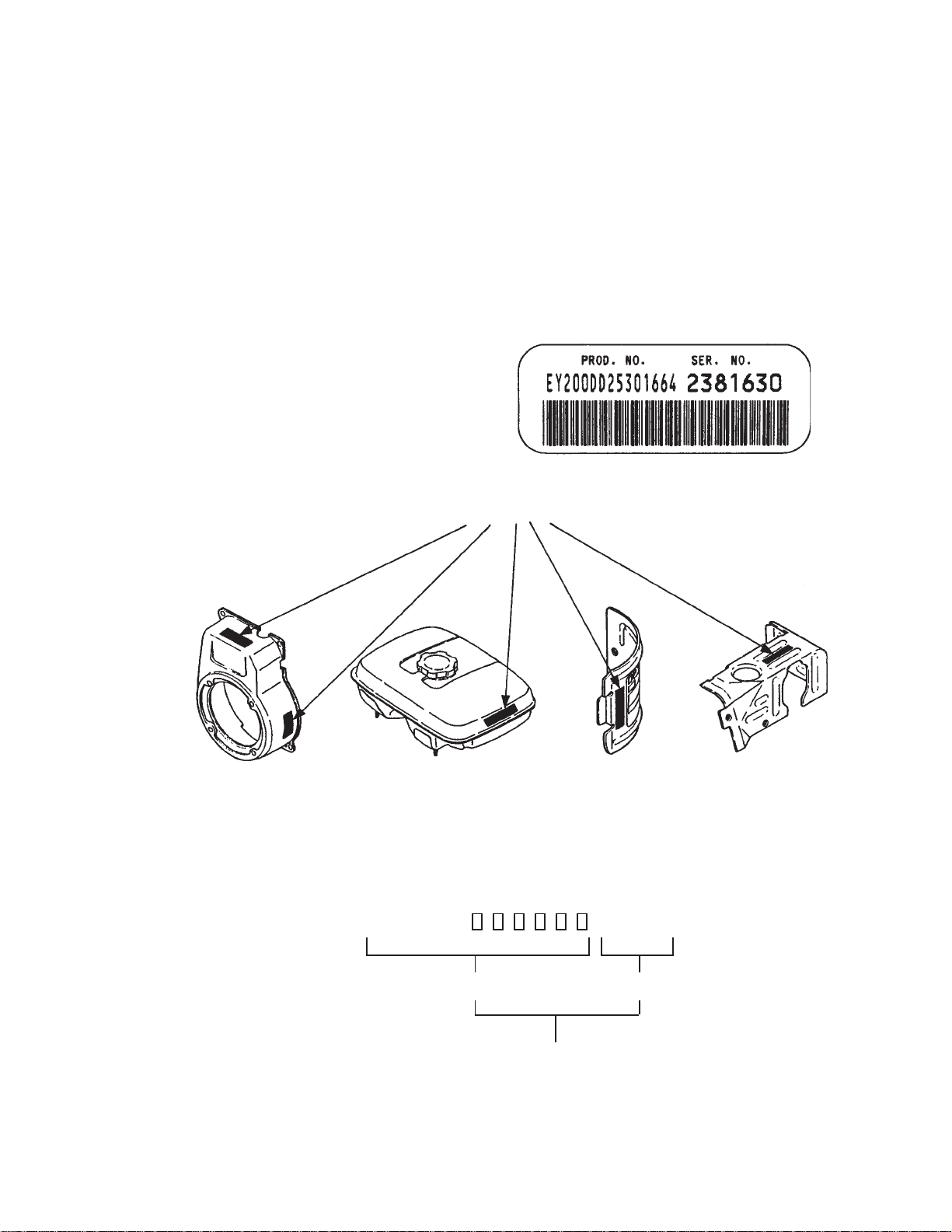
All Robin 4 cycle engines have a Product Number label similar to the label illustrated below.
PRODUCT NUMBER LABEL
PRODUCT NUMBER LABEL LOCATIONS
The Product Number Label has a 15 digit alphanumeric string that consists of the
SPECIFICATION (SPEC) number (11 digits) and the CODE number (4 digits). Please
note the illustration below:
E H 2 5 2
SPEC NO. (11 digits) CODE NO. (4 digits)
PRODUCT NO. (15 digits)
EH25-2 - 3 - '99 - 7
X X X X
Page 4
MANUAL LAYOUT
①①
①
①①
②②
②
②②
①①
①
①①
④④
④
④④
⑥⑥
⑥
⑥⑥
⑦⑦
⑦
⑦⑦
⑨⑨
⑨
⑨⑨
②②
②
②②
③③
③
③③
③③
③
③③
⑤⑤
⑤
⑤⑤
④④
④
④④
1. SECTION NAME Parts are broadly classified according to their functions.
Refer to the Group Index (table of contents) for respective section name.
2. FIG. No. The FIG. number indexes the reference and part numbers to the illustration. Figure numbers that
vary only in the tens place (i.e..: 700 and 710) are in a group of the same section (i.e..: Electrical
Device Group).
3. REF. No . The Reference number identifies the part illustration with the corresponding part number in the
part list.
4. SUBASSEMBLY SUBASSEMBLY parts of part assembly are listed below the assembly part. The subassembly
part reference number is indicated by the number led by "-" such as "-1", "-2".
5. PART NUMBER It is the number assigned for sales unit. Use the PART No. when making an order.
6. DESCRIPTION It is designation of the part.
2101-
-2100
⑧⑧
⑧
⑧⑧
7. QTY. Quantity of each part used for each product.
8. REMARKS This gives a distinctive feature and/or a supplementary comment for the type, the specification,
and the part concerned. It also shows part number(s) interchangeable for the part.
9. FROM-TO This section shows the CODE No. to indicate the history of progress in which improved parts
have been introduced in the product. The FROM-TO CODE No. helps to identify PART No.
being employed in the product concerned. See the examples below:
- The part is used in the product irrespective of CODE No.
2101- The part is used in the products with CODE No. of 2101 and after this number.
- 2100 The part is used in the products with CODE No. of 2100 and before this number.
EH25-2 - 4 - '99 - 7
○○○○
○○○○
○○○○
Page 5

GROUP INDEX
Group Name Page
CRANKCASE GROUP ............................................................................... 6
CRANKSHAFT GROUP ............................................................................. 8
INTAKE and EXHAUST GROUP.............................................................. 10
GOVERNOR GROUP ............................................................................... 12
COOLING and STARTING GROUP......................................................... 14
FUEL GROUP ........................................................................................... 16
FUEL GROUP - CARBURETOR.............................................................. 18
ELECTRIC DEVICE GROUP - RECOIL START...................................... 20
ELECTRIC DEVICE GROUP - ELECTRIC START ................................. 2 2
ELECTRIC DEVICE GROUP - ELECTRIC STARTER ............................ 2 4
ELECTRIC DEVICE GROUP - OIL SENSOR.......................................... 26
INDEX OF DESCRIPTION SYMBOLS
SYMBOL DESCRIPTION
AY ..........................ASSEMBLY
CP .......................... COMPLETE
EX .......................... EXPORT (from Japan)
FIG.........................FIGURE
FR. ......................... FRONT
".............................. INCH
INCL....................... INCLUDE
~L ........................... LITER
L= ........................... LENGTH (in. mm)
L.H. (LH) ................ LEFT-HAND SIDE
MECH ....................MECHANICAL
NO (NON) .............. NONE
OPT. .......................OPTIONAL
O.S......................... OVER SIZE
SYMBOL DESCRIPTION
P= .......................... PITCH (in mm)
P.T.O. (PTO) .......... POWER TAKE OFF
REF. .......................REFERENCE
R.H. (RH) ............... RIGHT HAND SIDE
RR. .........................REAR
STD........................STANDARD
SW .........................SWITCH
T=........................... THICKNESS (in mm)
UN ..........................UNIT
U.S. ........................ UNDER SIZE
~V .......................... VOLTAGE
~W ......................... WATT
W/ .......................... WITH
W/O ........................WITHOUT
EH25-2 - 5 - '99 - 7
Page 6
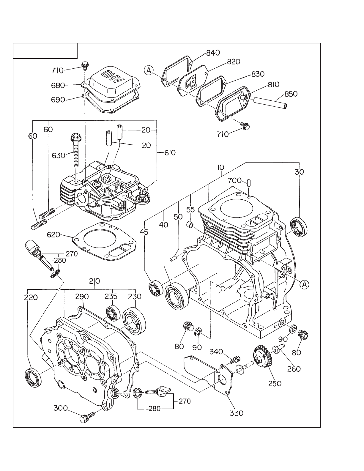
SECTION 1 CRANKCASE GROUP
FIG. 100
EH25-2 - 6 - '99 - 7
Page 7

SECTION 1 CRANKCASE GROUP
REF. PART NO. DESCRIPTION QT Y. REMARKS FROM-TO FIG.
10 254-10101-31 CRANKCASE CP 1 100
254-10102-31 CRANKCASE CP 1 electric start type 100
20 132-12AA0-80 VALVE GUIDE 2 STD. 100
30 044-03000-30 OIL SEAL 1 30 x 45 x 8 100
40 060-03000-20 BALL BEARING 1 BB-6206C3 060-03002-20 100
45 060-01500-10 BALL BEARING 1 BB-6202C3 100
50 031-00600-20 DOWEL PIN 2 100
55 142-55601-03 PIPE 2 electric start type 100
60 010-50802-90 STUD 2 100
80 040-11400-30 PLUG 2 100
90 021-11400-20 GASKET 2 100
210 254-11003-01 MAIN BEARING COVER CP 1 metric 100
220 044-03000-30 OIL SEAL 1 30 x 45 x 8 100
230 060-03000-20 BALL BEARING 1 BB-6206C3 060-03002-20 100
235 060-01500-10 BALL BEARING 1 D,DS type BB-6202C3 100
060-02800-10 BALL BEARING 1 BB-62/28C3 100
250 234-45001-01 GOVERNOR GEAR CP 1 100
260 205-41901-03 GOVERNOR SLEEVE 1 100
270 227-63601-07 OIL GAUGE AY 2 100
227-63601-07 OIL GAUGE AY 1 w/ OIL SENSOR 100
-280 021-31600-20 GASKET 2 100
021-31600-20 GASKET 1 w/ OIL SENSOR 100
290 254-16001-03 GASKET, BEARING COVER 1 100
300 001-13083-00 BOLT AND WASHER AY 8 100
330 254-17502-13 OlL SHELTER (SENSOR) 1 w/ OIL SENSOR 100
340 004-35051-00 SCREW AND WASHER AY 3 w/ OIL SENSOR 100
610 270-13001-01 CYLINDER HEAD CP 1 100
620 254-15001-13 GASKET, HEAD 1 100
630 011-01000-40 FLANGE BOLT 4 100
680 270-15503-03 ROCKER COVER 1 100
690 270-16004-03 GASKET, ROCKER COVER 1 100
700 031-00600-20 DOWEL PIN 2 100
710 011-00600-20 FLANGE BOLT 6 100
810 254-14301-01 BREATHER COVER CP 1 100
820 254-14401-11 BREATHER PLATE CP 1 100
830 246-16006-03 GASKET, BREATHER COVER 1 100
840 246-16007-13 GASKET, BREATHER PLATE 1 100
850 085-10800-00 RUBBER PIPE 1 8 x 11 x 60 100
085-10800-00 RUBBER PIPE 1 CYCLONE type 8 x 11 x 75 100
960 254-99001-07 GASKET SET 1 100
EH25-2 - 7 - '99 - 7
Page 8
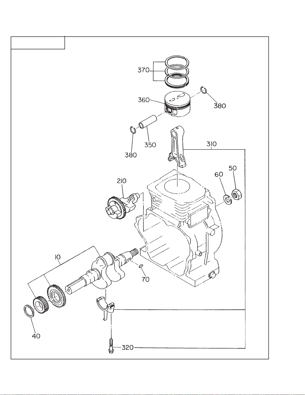
SECTION 2 CRANKSHAFT GROUP
FIG. 200
EH25-2 - 8 - '99 - 7
Page 9

SECTION 2 CRANKSHAFT GROUP
REF. PART NO. DESCRIPTION QT Y. REMARKS FROM-TO FIG.
10 254-20901-01 CRANKSHAFT CP 1 SAE 1" KEYED SHAFT 200
254-21001-01 CRANKSHAFT CP 1 SAE PUMP SHAFT 200
254-21201-01 CRANKSHAFT CP 1 SAE TAPER SHAFT 200
254-20201-01 CRANKSHAFT CP 1 metric DS type 200
254-20301-01 CRANKSHAFT CP 1 metric PUMP type 200
254-20701-01 CRANKSHAFT CP 1 metric GENERATOR type 200
40 023-03001-70 SPACER T=0.6 1 select 1 spacer only 200
023-03001-80 SPACER T=0.8 1 select 1 spacer only 200
023-03001-90 SPACER T=1.0 1 select 1 spacer only 200
50 002-18180-00 NUT 1 200
60 003-20180-00 SPRING WASHER 1 200
70 032-30300-10 WOODRUFF KEY 1 200
210 254-24101-03 BALANCER SHAFT 1 200
310 254-22501-00 CONNECTING ROD AY 1 200
320 246-23001-03 CONNECTING ROD BOLT 2 200
350 270-23301-03 PISTON PIN 1 200
360 270-23401-03 PISTON 1 STD. 200
270-23402-03 PISTON 1 oversize 0.25mm 200
270-23403-03 PISTON 1 oversize 0.50mm 200
370 254-23501-07 PISTON RING SET 1 STD. 200
254-23502-07 PISTON RING SET 1 oversize 0.25mm 200
254-23503-07 PISTON RING SET 1 oversize 0.50mm 200
380 056-51800-10 CLIP 2 200
EH25-2 - 9 - '99 - 7
Page 10

SECTION 3 INTAKE and EXHAUST GROUP
FIG. 300
CYCLONE AIR CLEANER
TOP INLET TYPE
FOAM
AIR CLEANER
EH25-2 - 10 - '99 - 7
Page 11

SECTION 3 INTAKE and EXHAUST GROUP
REF. PART NO. DESCRIPTION QT Y. REMARKS FROM-TO FIG.
10 254-31701-41 CAMSHAFT CP 1 300
35 254-36401-13 RELEASE LEVER 1 300
36 005-19041-00 SPRING PIN 1 300
37 003-15220-00 SNAP RING 1 300
50 239-33301-13 TAPPET 2 300
60 246-33611-03 VALVE SPRING 2 300
70 246-33711-03 SPRING RETAINER 2 300
80 270-33401-03 INTAKE VALVE 1 300
90 270-33501-03 EXHAUST VALVE 1 300
95 246-35501-03 COLLET VALVE 4 300
210 270-35301-03 PUSH ROD 2 300
220 261-36001-A3 ROCKER ARM 2 300
230 269-35801-03 BOLT, PIVOT 2 300
240 017-00600-90 NUT 2 300
260 270-36501-03 GUIDE PLATE 1 300
310 270-30101-01 MUFFLER CP 1 300
320 254-34201-11 MUFFLER COVER 1 300
340 246-35201-03 GASKET, MUFFLER 1 300
350 017-00800-30 NUT 2 300
360 015-20060-90 TAPPING BOLT 4 300
363 015-20601-00 TAPPING BOLT 1 300
365 001-10081-60 BOLT AND WASHER AY 1 300
430 270-34801-03 EXHAUST PIPE COVER 1 300
440 246-37001-07 DEFLECTOR AY 1 300
445 015-00400-60 TAPPING SCREW 3 300
500 254-33001-01 INTAKE PIPE CP 1 300
505 010-50601-91 STUD 2 300
510 254-32613-10 AIR CLEANER AY 1 CYCLONE, top inlet type 300
-2 234-36003-08 PACKING 1 CYCLONE, top inlet type 300
-3 207-32690-08 GROMMET 1 CYCLONE, top inlet type 300
510 270-32601-00 AIR CLEANER AY 1 FOAM AIR CLEANER type 300
-2 234-36003-08 PACKING 1 FOAM AIR CLEANER type 300
-13 270-32650-08 PLATE 1 FOAM AIR CLEANER type 300
-520 270-32610-08 CLEANER ELEMENT 1 FOAM AIR CLEANER type 300
520 234-32604-07 ELEMENT SET 1 CYCLONE type 300
540 234-32901-03 INSULATOR 1 300
555 246-36001-13 GASKET, INTAKE PIPE 1 300
556 001-13082-80 BOLT AND WASHER AY 3 300
560 234-35902-03 GASKET 2, INSULATOR 2 300
570 226-39212-00 NUT AND WASHER AY 2 CYCLONE, top inlet type 300
002-38060-00 FLANGE NUT 2 FOAM AIR CLEANER type 300
580 001-10061-20 BOLT AND WASHER AY 2 CYCLONE, top inlet type 300
650 230-43901-01 CHOKE KNOB 1 CYCLONE, top inlet type 300
EH25-2 - 11 - '99 - 7
Page 12

SECTION 4 GOVERNOR GROUP
FIG. 400
MANUAL ONLY THROTTLE
MANUAL THROTTLE CONTROL with REMOTE CABLE OPTION
EH25-2 - 12 - '99 - 7
Page 13

SECTION 4 GOVERNOR GROUP
REF. PART NO. DESCRIPTION QT Y. REMARKS FROM-TO FIG.
10 254-42301-23 GOVERNOR LEVER 1 400
20 246-42201-23 GOVERNOR SHAFT 1 400
30 254-42701-01 GOVERNOR ROD CP 1 400
40 254-42801-03 ROD SPRING 1 400
50 003-13060-00 CLIP 2 400
60 001-14063-00 BOLT AND WASHER AY 1 400
70 018-60600-20 NUT 1 400
80 254-42501-13 GOVERNOR SPRING 1 400
310 270-43302-00 SPEED CONTROL AY 1 manual w/remote cable option 400
270-43301-00 SPEED CONTROL AY manual only control 400
320 270-43302-01 SPEED CONTROL CP 1 manual w/remote cable option 400
270-43301-01 SPEED CONTROL 1 manual only control 400
330 227-43601-03 KNOB 1 400
340 270-43501-03 STOP PLATE 1 400
345 004-31042-50 SCREW 1 400
346 269-45503-03 IDLE SET SPRING 1 400
350 227-45002-03 SPRING WASHER 1 400
360 004-31063-00 SCREW 1 400
370 002-27060-00 NUT 1 400
380 011-00600-50 FLANGE-BOLT 1 manual w/remote cable option 400
011-00600-30 FLANGE BOL T 1 manual only control 400
410 254-44201-23 WIRE BRACKET 1 manual w/remote cable option 400
440 004-31040-80 SCREW 1 manual w/remote cable option 400
450 002-27060-00 NUT 1 manual w/remote cable option 400
EH25-2 - 13 - '99 - 7
Page 14

SECTION 5 COOLING and STARTING GROUP
FIG. 500
EH25-2 - 14 - '99 - 7
Page 15

SECTION 5 COOLING and STARTING GROUP
REF. PART NO. DESCRIPTION QT Y. REMARKS FROM-TO FIG.
10 254-53450-01 BLOWER HOUSING CP 1 BLACK 500
254-53550-11 BLOWER HOUSING CP 1 BLACK, electric start type 500
20 270-91703-03 LABEL, TRADE MARK 1 ROBIN/SUBARU 500
40 011-00600-20 FLANGE BOLT 5 500
45 073-20049-50 LABEL, RECOIL OHV 1
90 254-52701-03 HEAD COVER 1 500
210 270-50201-00 RECOIL STARTER AY 1 D type 500
-1 270-50115-08 SPIRAL SPRING 1 500
-2 270-50120-08 REEL 1 500
-3 270-50110-08 STARTER ROPE 1 500
-4 261-50100-08 STARTER KNOB 1 500
-5 270-50125-08 RATCHET 2 500
-6 227-50131-08 FRICTION SPRING 1 500
-11 270-50145-08 STARTER PULEY 1 500
-35 270-50261-08 RATCHET GUIDE 1 D type 500
-49 227-50152-08 SET SCREW 1 500
220 011-00600-10 FLANGE BOLT 4 500
EH25-2 - 15 - '99 - 7
Page 16

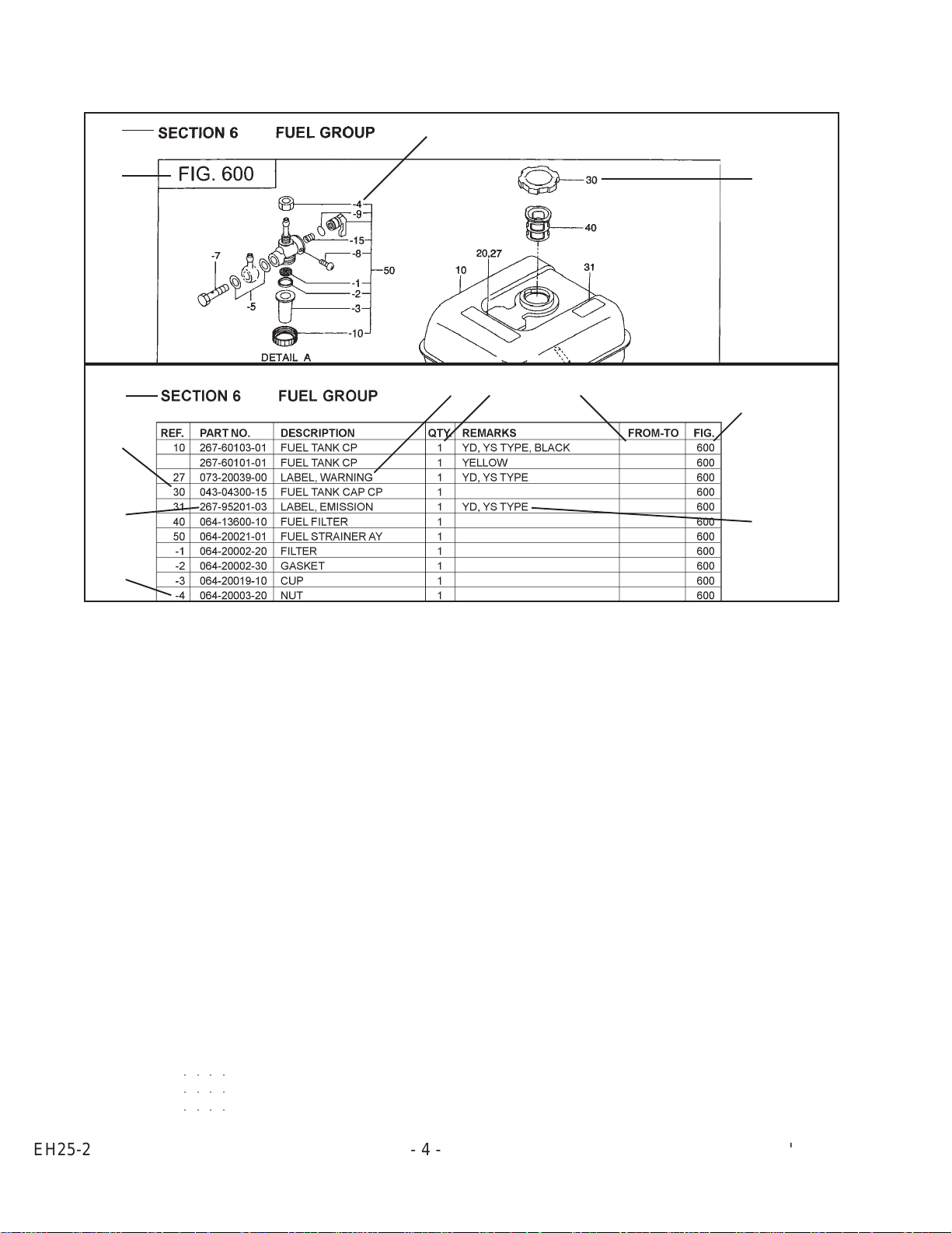
SECTION 6 FUEL GROUP
FIG. 600
EH25-2 - 16 - '99 - 7
Page 17

SECTION 6 FUEL GROUP
REF. PART NO. DESCRIPTION QT Y. REMARKS FROM-TO FIG.
10 254-61050-11 FUEL TANK CP 1 BLACK 600
20 073-20039-00 LABEL, CAUTION 1 600
30 043-04300-15 FUEL TANK CAP CP 1 600
40 064-13600-10 FUEL FILTER CP 1 600
50 064-20086-00 FUEL STRAINER AY 1 600
-1 064-20041-10 FILTER 1 600
-2 064-20014-30 RUBBER PACKING 1 600
-3 064-20014-10 CUP 1 600
-4 064-20023-60 LOCK NUT 1 600
-8 064-20027-90 LOCK BOLT 1 600
-15 064-20032-30 SPRING 1 600
70 234-62601-01 FUEL PIPE CP 1 600
80 085-10600-00 RUBBER PIPE 1 6 x 12 x 75 600
90 056-11100-20 HOSE CLAMP 2 600
105 001-13082-00 BOLT AND WASHER AY 4 600
EH25-2 - 17 - '99 - 7
Page 18

SECTION 6 FUEL GROUP - CARBURETOR
FIG. 610
EH25-2 - 18 - '99 - 7
Page 19

SECTION 6 FUEL GROUP - CARBURETOR
REF. PART NO. DESCRIPTION QT Y. REMARKS FROM-TO FIG.
210 254-62523-00 CARBURETOR AY 1 CYCLONE, top inlet type 610
254-62560-10 CARBURETOR AY 1 FOAM AIR CLEANER type 610
-1 239-62535-08 THROTTLE VALVE 1 610
-2 209-62351-08 SCREW 2 610
-3 254-62525-08 VALVE, CHOKE 1 610
-4 237-62451-08 SCREW PANHEAD 2 610
-5 254-62420-08 PILOT JET 1 610
-6 246-62436-08 ADJUSTER 1 610
-7 230-62448-08 SPRING 1 610
-8 234-62521-08 CHOKE LEVER AY 1 CYCLONE, top inlet type 610
234-62520-08 CHOKE LEVER AY 1 FOAM AIR CLEANER type 610
-9 239-62560-08 RING 1 CYCLONE, top inlet type 610
234-62550-08 RING 1 FOAM AIR CLEANER type 610
-11 254-62531-08 SHAFT AY, THROTTLE 1 CYCLONE, top inlet type 610
254-62530-08 SHAFT AY, THROTTLE 1 FOAM AIR CLEANER type 610
-12 224-62544-08 BOLT 1 610
-13 226-62550-08 RING 1 610
-14 224-62312-08 NEEDLE VALVE AY 1 610
-15 214-62515-08 FLOAT PIN 1 610
-16 224-62552-08 FLOAT CHAMBER BODY 1 610
-17 207-62345-08 INSERT WASHER 1 610
-18 206-62540-08 PACKING, CHAMBER 1 610
-19 234-62506-08 FLOAT AY 1 610
-20 254-62440-08 MAIN NOZZLE 1 610
-22 254-62403-08 MAIN JET 1 CYCLONE, top inlet type 610
254-62402-08 MAIN JET 1 FOAM AIR CLEANER type 610
-23 246-62455-08 BOLT 1 CYCLONE, top inlet type 610
-24 224-62569-18 CLIP 1 CYCLONE, top inlet type 610
226-62701-18 CLIP 1 FOAM AIR CLEANER type 610
-32 106-62392-08 SEAL 1 CYCLONE, top inlet type 610
-40 246-62435-08 ADJUST SCREW 1 610
-41 230-62446-08 SPRING 1 610
-61 247-62550-08 CAP 1 CYCLONE, top inlet type 610
-62 236-62680-08 SEAL 1 CYCLONE, top inlet type 610
-89 246-62425-08 GUIDE HOLDER 1 610
-101 156-62351-08 PACKING 1 CYCLONE, top inlet type 610
-121 246-62551-08 CAP 1 610
EH25-2 - 19 - '99 - 7
Page 20

SECTION 7A ELECTRIC DEVICE GROUP - RECOIL START
FIG. 700
EH25-2 - 20 - '99 - 7
Page 21

SECTION 7A ELECTRIC DEVICE GROUP - RECOIL START
REF. PART NO. DESCRIPTION QT Y. REMARKS FROM-TO FIG.
10 234-70201-11 FLYWHEEL CP 1 700
11 254-79430-21 IGNITION COIL CP 1 700
30 001-14062-50 BOLT AND WASHER AY 2 700
60 066-00003-61 SWITCH AY 1 700
70 015-00400-90 TAPPING SCREW 2 700
90 056-60001-90 CLAMP 1 700
056-61200-50 CLAMP 1 w/oil sensor 700
100 065-01400-31 SPARK PLUG 1 NGK B-6HS 700
065-01401-50 SPARK PLUG 1 EXPORT(CE) NGK (BR-6HS) 700
065-01410-30 SPARK PLUG 1 CHAMPION (L86C) 700
RL86C SPARK PLUG 1 EXPORT(CE) CHAMPION 700
110 065-50000-51 SPARK PLUG CAP 1 700
EH25-2 - 21 - '99 - 7
Page 22

SECTION 7B ELECTRIC DEVICE GROUP - ELECTRIC START
FIG. 710
EH25-2 - 22 - '99 - 7
Page 23

SECTION 7B ELECTRIC DEVICE GROUP - ELECTRIC START
REF. PART NO. DESCRIPTION QT Y. REMARKS FROM-TO FIG.
10 234-70203-11 FLYWHEEL CP 1 710
11 254-79430-21 IGNITION COIL CP 1 710
12 227-79632-01 CHARGE COIL CP 1 710
20 254-71002-03 RING GEAR 1 710
30 001-14062-50 BOLT AND WASHER AY 2 710
35 004-35062-50 SCREW AND WASHER AY 2 710
80 226-75501-03 GROMMET 1 710
90 056-60001-90 CLAMP 1 710
95 065-90000-10 PLUG TERMINAL 1 710
100 065-01400-31 SPARK PLUG 1 NGK B-6HS 710
065-01401-50 SPARK PLUG 1 EXPORT(CE) NGK (BR-6HS) 710
065-01410-30 SPARK PLUG 1 CHAMPION (L86C) 710
RL86C SPARK PLUG 1 EXPORT(CE) CHAMPION 710
110 065-50001-40 SPARK PLUG CAP 1 DS,BS type 710
175 206-75501-01 CLAMP CP 1 DS,BS type 710
176 004-31060-80 SCREW, PANHEAD 1 DS,BS type 710
EH25-2 - 23 - '99 - 7
Page 24

SECTION 7C ELECTRIC DEVICE GROUP - ELECTRIC STARTER
FIG. 720
EH25-2 - 24 - '99 - 7
Page 25

SECTION 7C ELECTRIC DEVICE GROUP - ELECTRIC STARTER
REF. PART NO. DESCRIPTION QT Y. REMARKS FROM-TO FIG.
120 254-70502-00 STARTING MOTOR AY 1 720
-1 254-70551-08 YOKE AY 1 720
-2 254-70541-08 BRUSH SUB AY 1 720
-4 254-70536-08 HOLDER AY 1 720
-6 254-70557-08 ARMATURE AY 1 720
-7 254-70522-08 CLUTCH SUB AY 1 720
-9 254-70502-08 HOUSING AY 1 720
-11 254-70505-08 FRAME AY 1 720
-16 227-70562-08 SNAP RING 1 720
-17 254-70574-08 BOLT, THROUGH 2 720
-20 227-70573-08 WASHER, PLATE 1 720
-23 254-70573-08 WASHER, PLATE SK 1 720
-33 227-70560-08 SPRING 1 720
-34 227-70561-08 NUT, PINION STOP 1 720
-40 254-70573-08 WASHER, PLATE SK 1 720
-41 254-70575-08 NUT 1 720
-44 254-70571-08 O-RING 2 720
-46 227-70571-08 0-RING 2 720
-48 254-70582-08 BUSHING 1 720
-50 254-70572-80 O-RING 1 720
130 001-14083-50 BOLT AND WASHER AY 2 720
190 073-20044-80 LABEL, BATTERY 1 720
200 254-75104-01 CONTROL BOX CP 1 720
210 073-20044-70 LABEL, STARTER SWITCH 1 720
212 002-17050-00 NUT 2 720
214 003-20050-00 SPRING WASHER 2 720
216 002-27060-00 NUT 2 720
218 003-20060-00 SPRING WASHER 2 720
220 066-00003-30 SWITCH 1 720
-1 066-00099-80 KEY, SWITCH 2 720
230 232-71401-01 DIODE RECTIFIER CP 1 720
240 004-35061-00 SCREW AND WASHER AY 1 720
250 234-73105-01 WIRE 5 CP 1 720
260 254-73102-01 WIRE 2 CP 1 720
296 002-27060-00 NUT 1 720
298 003-20060-00 SPRING WASHER 1 720
300 066-10000-10 MAGNETIC SWITCH 1 720
310 224-73201-01 WIRE 20 CP 1 720
330 232-73105-01 WIRE 5 CP 1 720
335 227-73102-01 WIRE 2 CP 1 720
350 214-78501-03 WIRE CASING 2 720
EH25-2 - 25 - '99 - 7
Page 26

SECTION 7D ELECTRIC DEVICE GROUP - OIL SENSOR
FIG. 760
EH25-2 - 26 - '99 - 7
Page 27

SECTION 7D ELECTRIC DEVICE GROUP - OIL SENSOR
REF. PART NO. DESCRIPTION QT Y. REMARKS FROM-TO FIG.
700 KS3-11028-01 OIL SENSOR CP 19 1 W/OIL SENSOR 760
760 214-73122-01 WIRE 22 CP 1 W/OIL SENSOR 760
790 214-79003-01 CLAMP CP 1 W/OIL SENSOR 760
EH25-2 - 27 - '99 - 7
Page 28

PRINTED IN THE USA
 Loading...