

Page 1

SERVICE
MANUAL
Models
EH09,
EH12-2 Rammer
ENGINES
PUB-ES1330
Rev. 12/01
Page 2
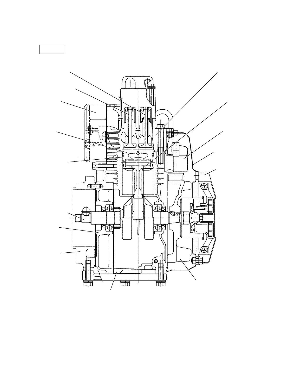
4-16 SECTIONAL VIEW OF ENGINE
EH09D
INTAKE VALVE
EXHAUST VALVE
MUFFLER
PISTON
PISTON RING
CYLINDER HEAD
PISTON PIN
IGNITION COIL
BLOWER HOUSING
RECOIL STARTER
P.T.O. SHAFT
MAIN
BEARING
COVER
ADAPTER
(
FLANGE
)
FLYWHEEL
CRANKCASE
Fig. 4-15
-
12
-
Page 3
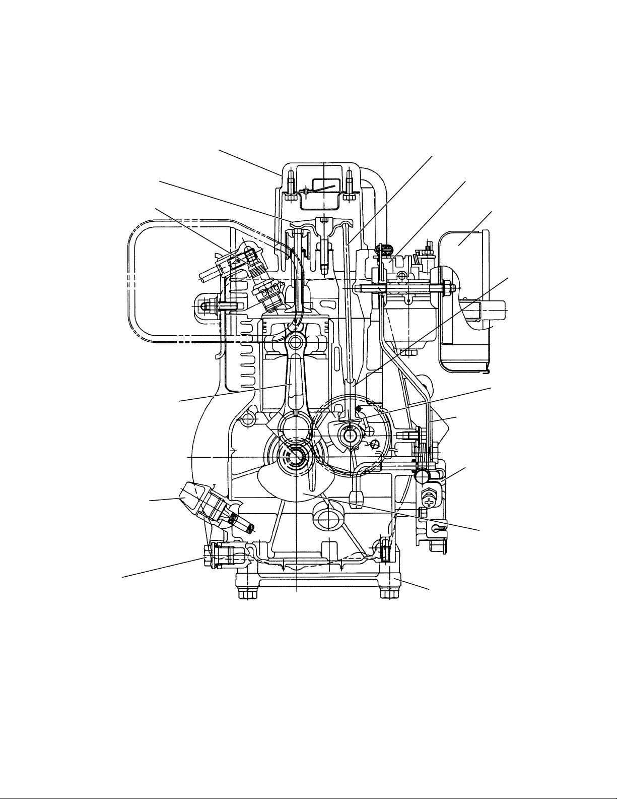
ROCKER COVER
PUSH ROD
ROCKER ARM
SPARK PLUG
CONNECTING ROD
CARBURETOR
AIR CLEANER
TAPPET
CAMSHAFT
GOVERNOR LEVER
SPEED CONTROL
LEVER
OIL GAUGE
PLUG
Fig. 4-16
-
13
-
CRANKSHAFT
STIFFENER
Page 4
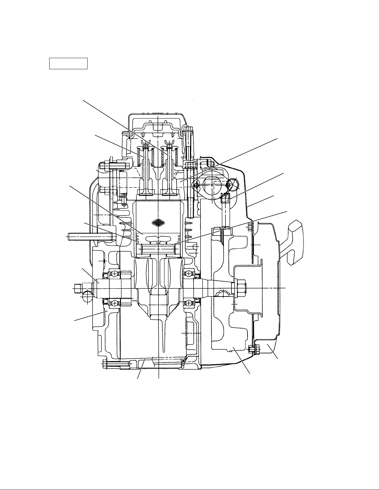
EH12-2D
INTAKE VALVE
EXHAUST VALVE
PISTON
PISTON RING
P.T.O. SHAFT
CYLINDER HEAD
IGNITION COIL
BLOWER HOUSING
PISTON PIN
MAIN
BEARING
COVER
CRANKCASE
Fig. 4-17
-
14
-
RECOIL STARTER
FLYWHEEL
Page 5
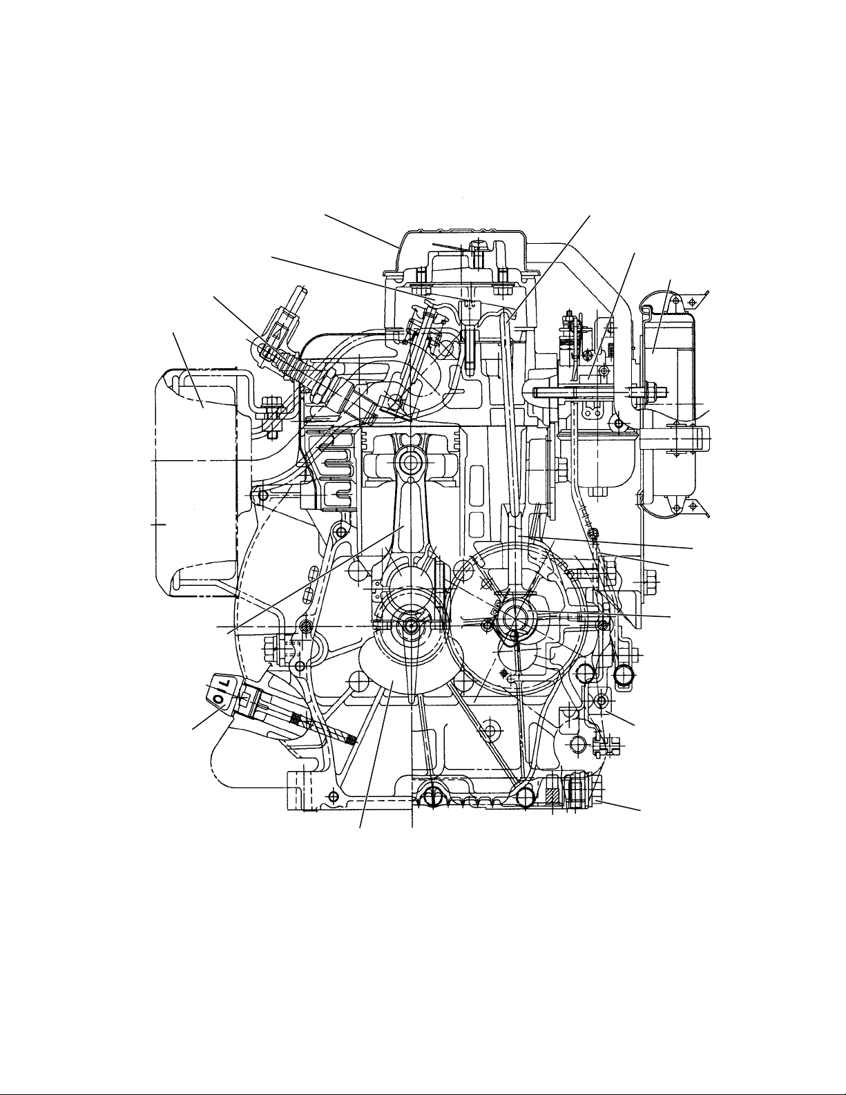
ROCKER COVER
PUSH ROD
ROCKER ARM
SPARK PLUG
MUFFLER
CONNECTING ROD
CARBURETOR
AIR CLEANER
TAPPET
GOVERNOR
LEVER
CAMSHAFT
OIL GAUGE
CRANKSHAFT
Fig. 4-18
-
15
-
SPEED CONTROL
LEVER
PLUG
Page 6
5. DISASSEMBLY AND REASSEMBLY
5-1 PREPARATIONS AND SUGGESTIONS
1) When disassembling the engine, memorize the locations of individual parts so that they can be
reassembled correctly. If you are uncertain of identifying some parts, it is suggested that tags be
attached to them.
2) Have boxes ready to keep disassembled parts by group.
3) To prevent losing and misplacing, temporarily assemble each group of disassembled parts.
4) Carefully handle disassembled parts, and clean them with washing oil if necessary.
5) Use the correct tools in the correct way.
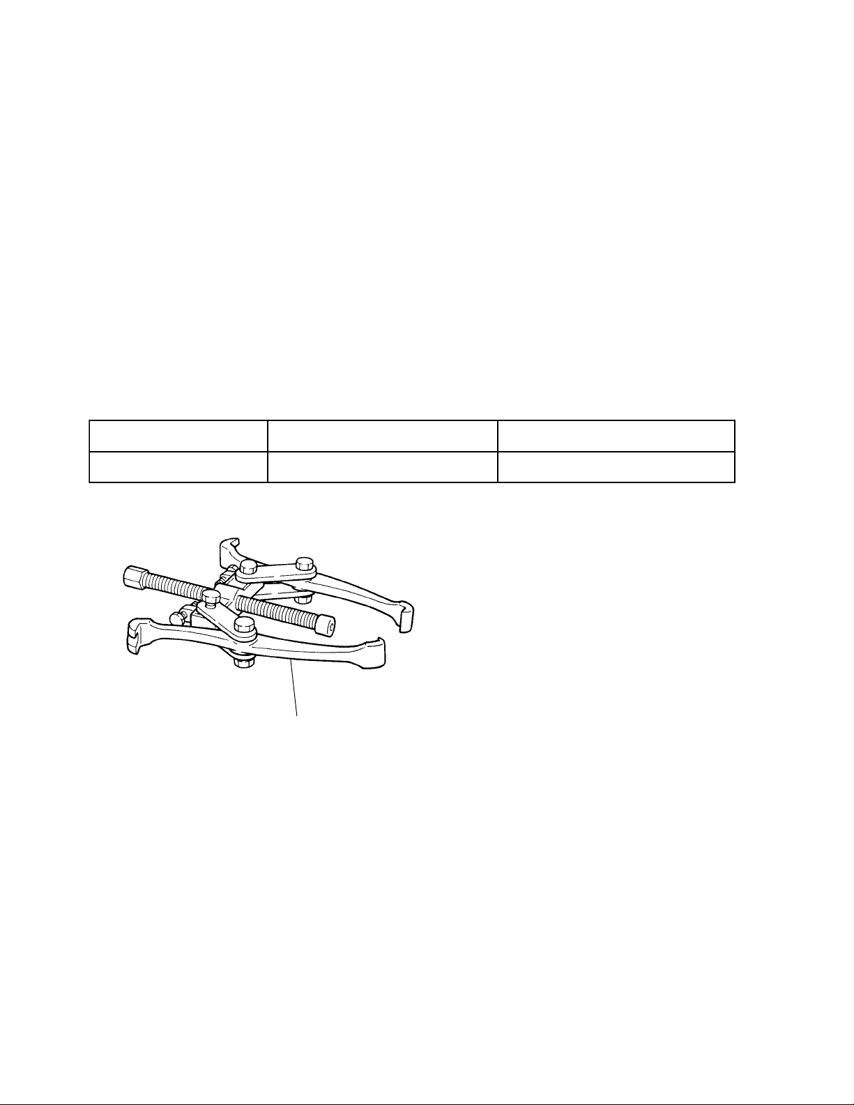
5-2 SPECIAL TOOLS (EH12-2D)
.oNlooTlooTesU
straptekraMrellupleehwylFleehwylfehtffognilluproF
FLYWHEEL PULLER
Fig. 5-1
-
16
-
Page 7
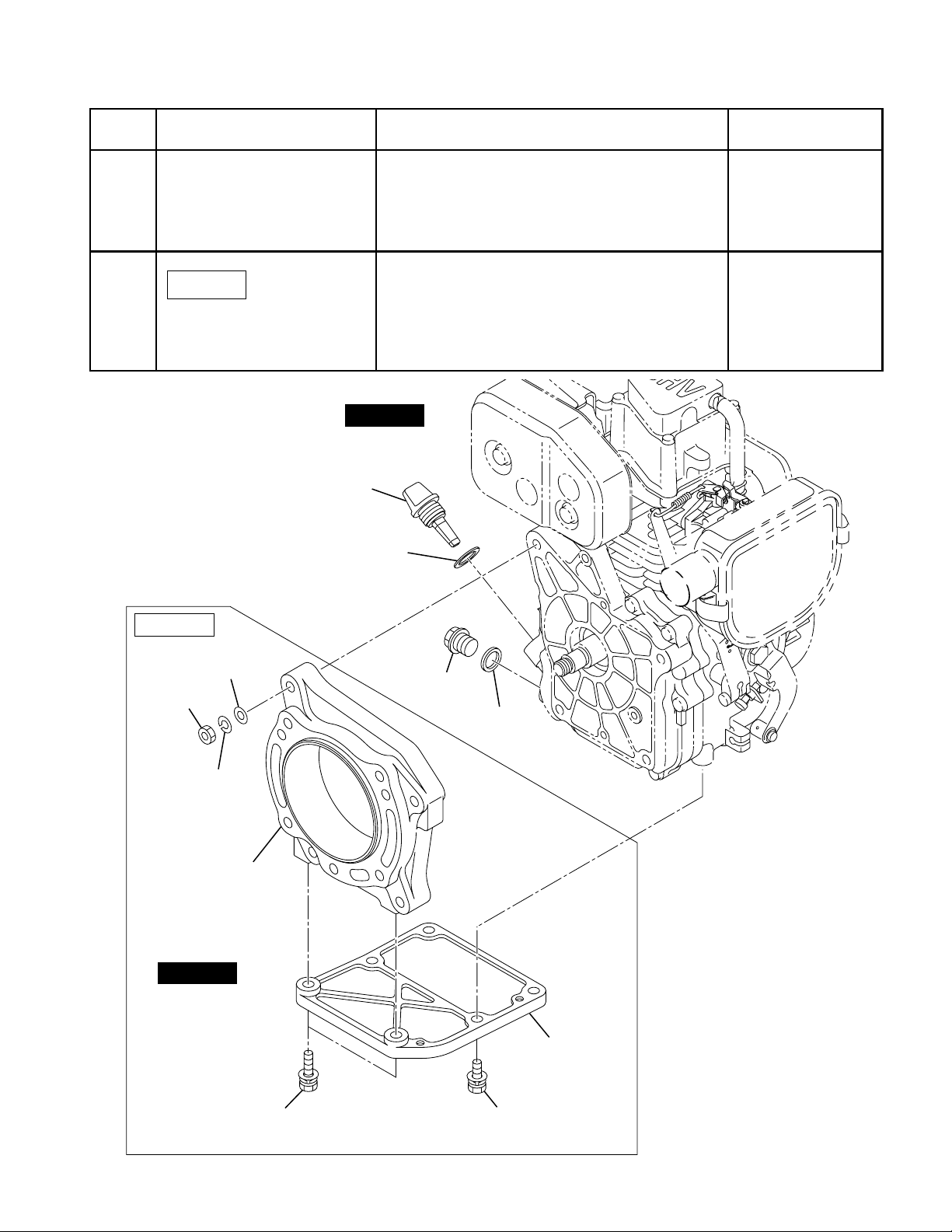
5-3 DISASSEMBLY PROCEDURES
petSevomerotstraPserudecorpdnaskrameRsrenetsaF
1niardlioenignE
lioevomer,ylkciuqlioegrahcsidoT)2(
.eguag
.lioniarddnagulpniardlioevomeR)1(
2
EH09D
EH09D
M8 NUT
: 4 pcs.
OIL LEVEL GAUGE
M8 WASHER
: 4 pcs.
reneffitSdnaretpadA
GASKET
.scp4:52x8M
.scp2:03x8M
,rehsaw,tun8M
:rehsawgnirps
scp4
STEP 1
OIL DRAIN
PLUG
GASKET
M8 SPRING
WASHER : 4 pcs.
ADAPTER
STEP 2
M8 x 30 BOLT AND
WASHER : 2 pcs.
STIFFENER
M8 x 25 BOLT AND
WASHER : 4 pcs.
-
17
-
Fig. 5-2
Page 8
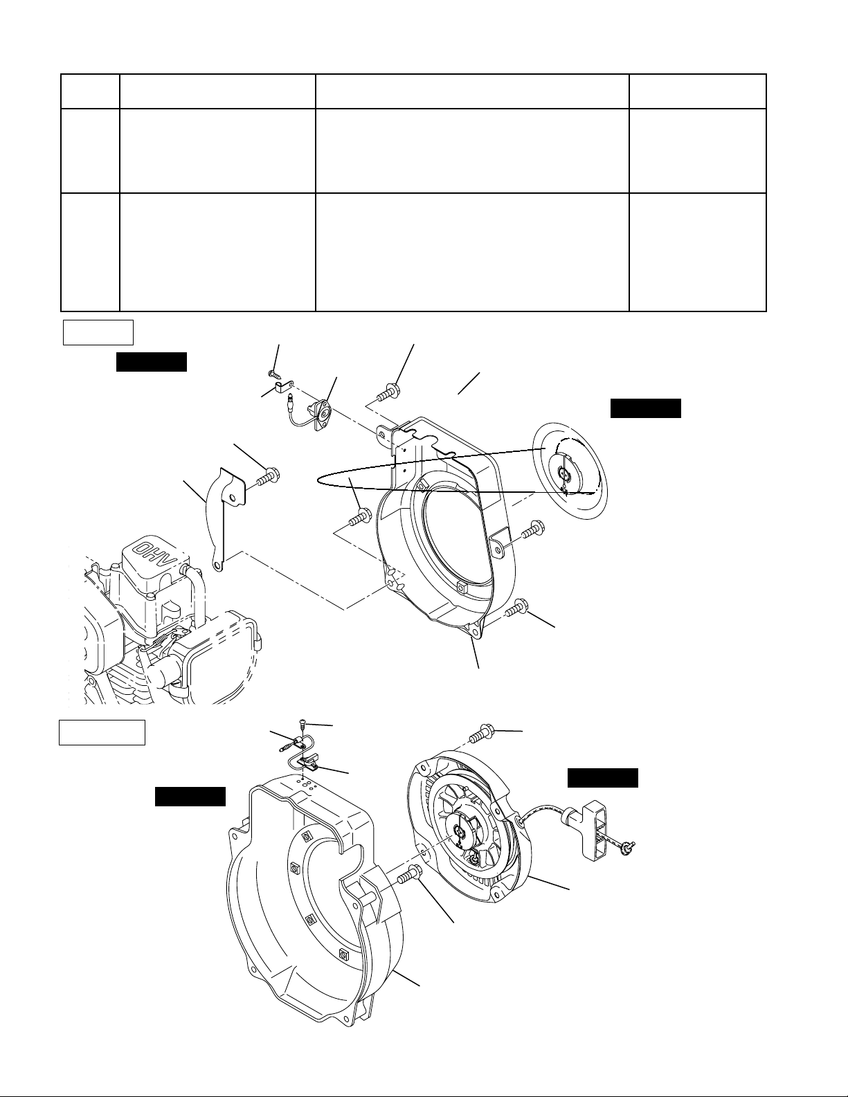
petSevomerotstraPserudecorpdnaskrameRsrenetsaF
3retratslioceR
.scp3;21x6M
)D90HE(
.scp4;8x6M
)D2-21HE(
4gnisuohrewolB
EH09D
STEP 4
M6 x 8 FLANGE BOLT
BLOWER
GUIDE CP
M4 TAPPING SCREW : 2 pcs.
STOP SWITCH
CLAMP
: 1 pce.
M6 x 12 FLANGE
BOLT : 1 pce.
M6 x 12 FLANGE BOLT : 1 pce.
M6 x 12 FLANGE
BOLT : 2 pcs.
neht,tsrifhctiwspotsfoeriwtcennocsiD
.esacknarcmorfgnisuohrewolbevomer
STEP 3
M6 x 12 FLANGE
BOLT: 1 pce.
.scp5;21x6M
)D90HE(
.scp2;8x6M
)D90HE(
.scp4;55x6M
)D2-21HE(
EH12-2D
STEP 4
CLAMP
M4 TAPPING
SCREW : 2 pcs.
STOP
SWITCH
M6 x 8 FLANGE
BOLT: 1 pce.
BLOWER HOUSING CP
M6 x 8 FLANGE BOLT
: 4 pcs.
STEP 3
M6 x 55 FLANGE BOLT
: 4 pcs.
BLOWER HOUSING CP
Fig. 5-3
-
18
-
Page 9
EH09D
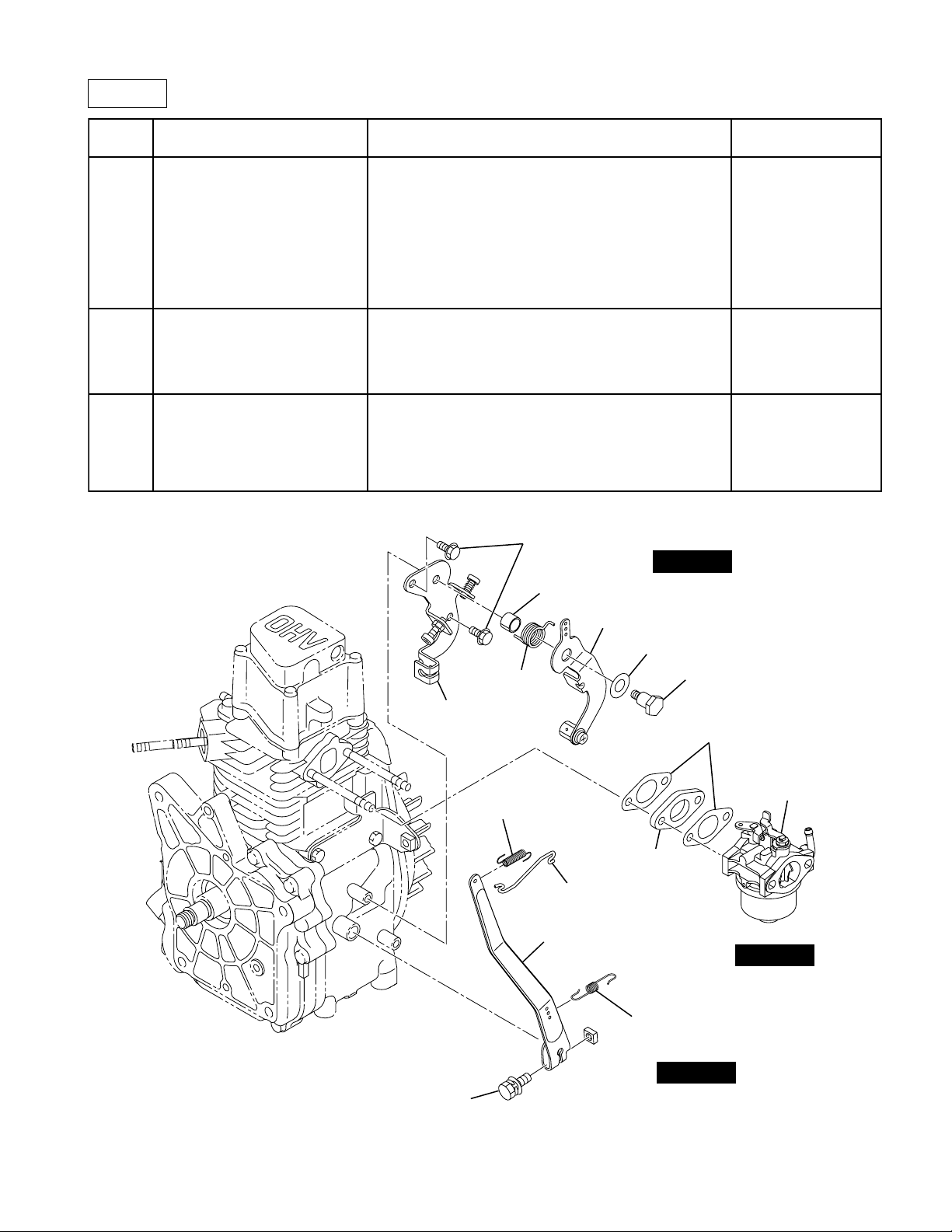
petSevomerotstraPserudecorpdnaskrameRsrenetsaF
7revelronrevoG
8roterubraC
9
ronrevogevomerdnatlobehtnesooL)1(
.ecp1;52x6M
.revel
ronrevogmorfgnirpsronrevogkoohnU)2(
.revel
ronrevogehthcihwnoelohehtkraM
.dekoohsignirps
gnikoohnuylluferacroterubracevomeR
ronrevogmorfgnirpsdordnadorronrevog
.revel
;tlobtovip6M
dnarevellortnocdeepS
etalpesab
.ecp1
egnalf8x6M
.scp2;tlob
M6 x 8 FLANGE
BOLT : 2 pcs.
SPACER
SPEED CONTROL
LEVER AY
STEP 9
BASE
PLATE CP
M6 BOLT AND
WASHER AY : 1 pce.
RETURN
SPRING
ROD SPRING
GOVERNOR LEVER
FRICTION WASHER
INSULATOR
GOVERNOR ROD
GOVERNOR SPRING
M6 PIVOT BOLT
: 1 pce.
GASKET (INSULATOR
CARBURETOR
STEP 8
STEP 7
)
Fig. 5-6
-
21
-
Page 10
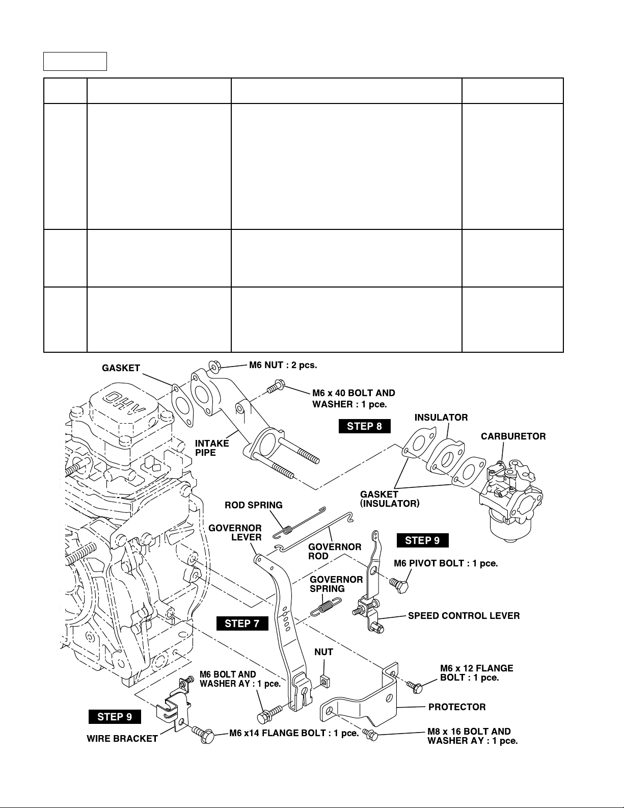
EH12-2D
petSevomerotstraPserudecorpdnaskrameRsrenetsaF
7revelronrevoG
8
9
epip
GASKET
.rotcetorpehtevomeR)1(
.ecp1;61x8M
.ecp1;41x6M
ronrevogevomerdnatlobehtnesooL)2(
.ecp1;03x6M
.revel
ronrevogmorfgnirpsronrevogkoohnU)3(
.revel
ronrevogehthcihwnoelohehtkraM
.dekoohsignirps
ekatnidnaroterubraC
ronrevogmorfgnirpsdordnadorronrevog
gnikoohnuylluferacroterubracevomeR
.scp2;tun6M
.ecp1;04x6M
.revel
;tlobtovip6M
dnarevellortnocdeepS
tekcarberiw
.ecp1
egnalf41x6M
.scp1;tlob
M6 NUT : 2 pcs.
M6 x 40 BOLT AND
WASHER : 1 pce.
STEP 8
INTAKE
PIPE
INSULATOR
CARBURETOR
STEP 9
WIRE BRACKET
ROD SPRING
GOVERNOR
LEVER
STEP 7
M6 BOLT AND
WASHER AY : 1 pce.
M6 x14 FLANGE BOLT : 1 pce.
Fig. 5-7
-
GOVERNOR
ROD
GOVERNOR
SPRING
NUT
22
-
GASKET
(
INSULATOR
M6 PIVOT BOLT : 1 pce.
)
STEP 9
SPEED CONTROL LEVER
M6 x 12 FLANGE
BOLT : 1 pce.
PROTECTOR
M8 x 16 BOLT AND
WASHER AY : 1 pce.
Page 11
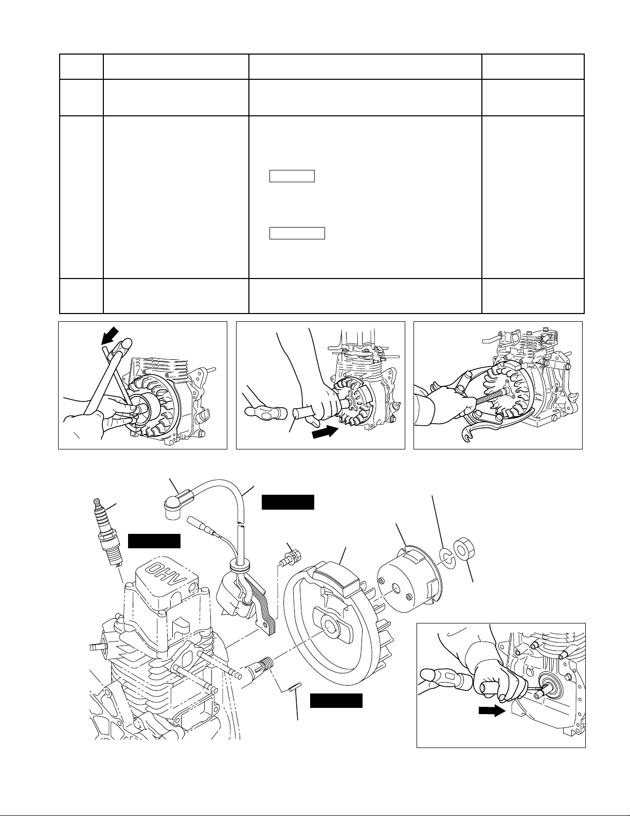
petSevomerotstraPserudecorpdnaskrameRsrenetsaF
01liocnoitingI
11leehwylF
21gulpkrapS
EH09D
)2(
EH12-2D
.gulpkrapsmorfpacgulpkrapsevomeR)1(
.esacknarcmorfliocnoitingievomeR)2(
.leehwylfmorfyellupretratsehtevomeR)1(
tungninetsafleehwylfnohcnerwtekcosecalP
eeS(.remmahhtiwrevelehtfopitekirtsdna
).9-5.giF
gnisutfahsknarcfodneleehwylfnopaT
.leehwylfevomerotrabmunimula
).01-5.giFeeS(
.rellupleehwylfehtgnisuleehwylfevomeR
).11-5.giFeeS(
.tfahsknarcmorfyekehtevomeR)3().21-5.giFeeS(
)D90HE(A6RMB,A6MB:KGN
)D2-21HE(SE6RB,SE6B:KGN
rehsaw
rehsaw
.scp2;52x6M
gnirps,tun21M
gnirps,tun41M
ALUMINUM BAR
Fig. 5-9 Fig. 5-10 Fig. 5-11
SPARK PLUG CAP
SPARK
PLUG
STEP 12
IGNITION COIL CP
STEP 10
M6 x 25 BOLT AND
WASHER AY
: 2 pcs.
FLYWHEEL CP
M12 SPRING WASHER : 1 pce. (EH09D)
M14 SPRING WASHER : 1 pce. (EH12-2D)
STARTING
PULLEY
M12 NUT : 1 pce. (EH09D)
M14 NUT : 1 pce. (EH12-2D)
STEP 11
WOODRUFF KEY
Fig. 5-8
-
23
Fig. 5-12
-
Page 12
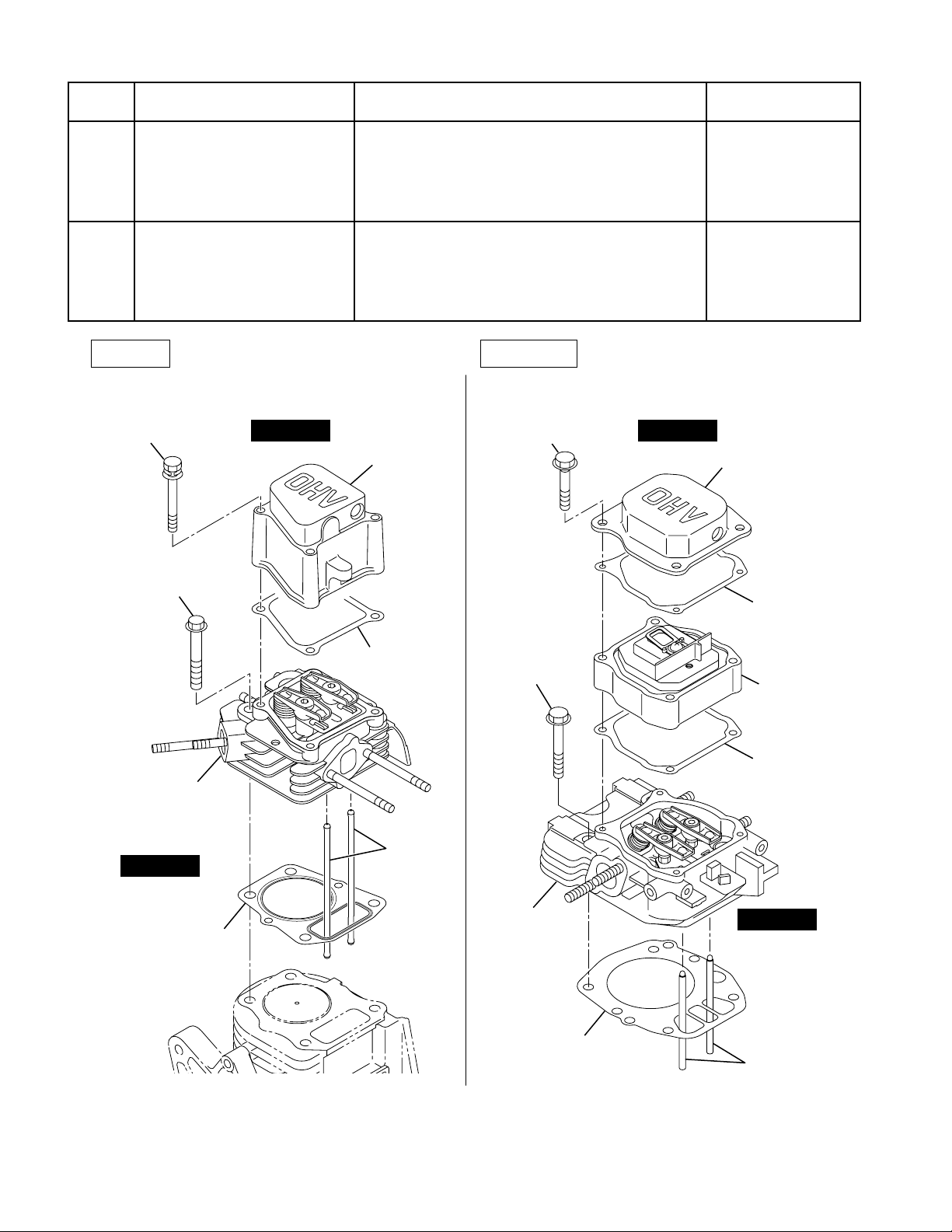
petSevomerotstraPserudecorpdnaskrameRsrenetsaF
31revocrekcoR
41daehrednilyC
.daehrednilyc
.esacknarc
EH09D EH12-2D
M6 x 60 BOLT AND
WASHER AY : 4 pcs.
M8 x 55 FLANGE
BOLT : 4 pcs.
STEP 13 STEP 13
ROCKER COVER
M6 x 40 FLANGE
BOLT : 4 pcs.
morfteksagdnarevocrekcorevomeR
.scp4;06x6M
)D90HE(
.scp4;04x6M
)D2-21HE(
morfteksagdnadaehrednilycevomeR)1(
.scp4;55x8M
)D90HE(
.rednilycmorfsdorhsupevomeR)2(
.scp4;56x8M
)D2-21HE(
ROCKER COVER
GASKET
CYLINDER
HEAD CP
STEP 14
GASKET
GASKET
PUSH ROD
M8 x 65 FLANGE
BOLT : 4 pcs.
CYLINDER
HEAD CP
Fig. 5-13
GASKET
SPACER
(
BREATHER
GASKET
STEP 14
PUSH ROD
)
-
24
-
Page 13
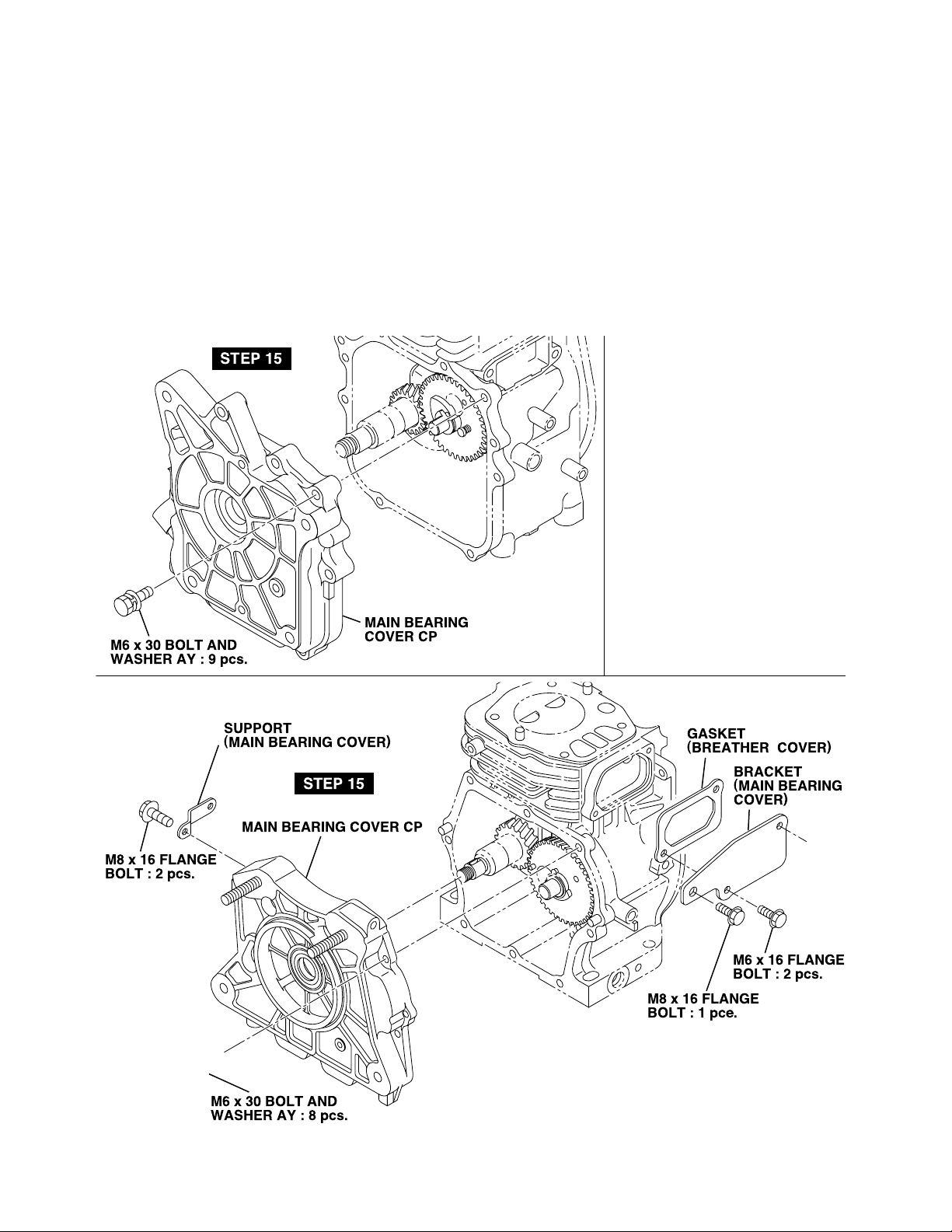
STEP 15
M6 x 30 BOLT AND
WASHER AY : 9 pcs.
MAIN BEARING
COVER CP
M8 x 16 FLANGE
BOLT : 2 pcs.
SUPPORT
(
MAIN BEARING COVER
STEP 15
MAIN BEARING COVER CP
M6 x 30 BOLT AND
WASHER AY : 8 pcs.
)
-
25
-
GASKET
(
BREATHER COVER
BRACKET
(
MAIN BEARING
COVER
M6 x 16 FLANGE
BOLT : 2 pcs.
M8 x 16 FLANGE
BOLT : 1 pce.
)
)
Page 14

petSevomerotstraPserudecorpdnaskrameRsrenetsaF
tfahsknarcfodneleehwylfnoylthgilpaT
81tfahsknarC
.esacknarc
morfevomerotremmahtfosahtiw
.laeslioegamadottonluferaceB*
STEP 18
CRANKSHAFT
Fig. 5-19
Fig. 5-20
-
28
-
Page 15
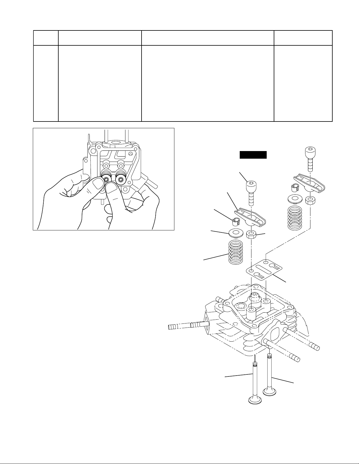
petSevomerotstraPserudecorpdnaskrameRsrenetsaF
tsuahxednaekatnI
sevlav
ekat,reniatergnirpsehtnwodsserP)1(
evomernehtdna,evlavtelloctuo
.gnirpsevlavdnareniatergnirps
91
.daehrednilycmorf
sevlavtsuahxednaekatnievomeR)2(
ehtmorftisopedmugdnanobracnaelC*
.sediugdnastrop,staesevlav,sevlav
.sediugdnastaesevlav,sevlavtcepsnI
STEP 19
BOLT (PIVOT) : 2 pcs.
ROCKER ARM
COLLET
Fig. 5-22
SPRING
RETAINER
VALVE
SPRING
EXHAUST VALVE
M6 NUT
: 2 pcs.
GUIDE PLATE
INTAKE VALVE
Fig. 5-21
-
29
-
Page 16
5-4 REASSEMBLY PROCEDURES
● PRECAUTIONS FOR REASSEMBLY
1) Clean parts thoroughly before reassembly.
Pay close attention to the cleanliness of piston, cylinder, crankshaft, connecting rod and bearings.
2) Scrape off all carbon deposits from cylinder head, piston top and piston ring grooves.
3) Check lip of oil seals. Replace oil seal if the lip is damaged. Apply oil to the lip before reassembly.
4) Replace all the gaskets with new ones.
5) Replace keys, pins, bolts, nuts, etc., if necessary.
6) Torque bolts and nuts to specification refer to the "TORQUE SPECIFICATIONS" (See page 76).
7) Apply oil to rotating and sliding portions.
8) Check and adjust clearances and end plays where specified in this manual.
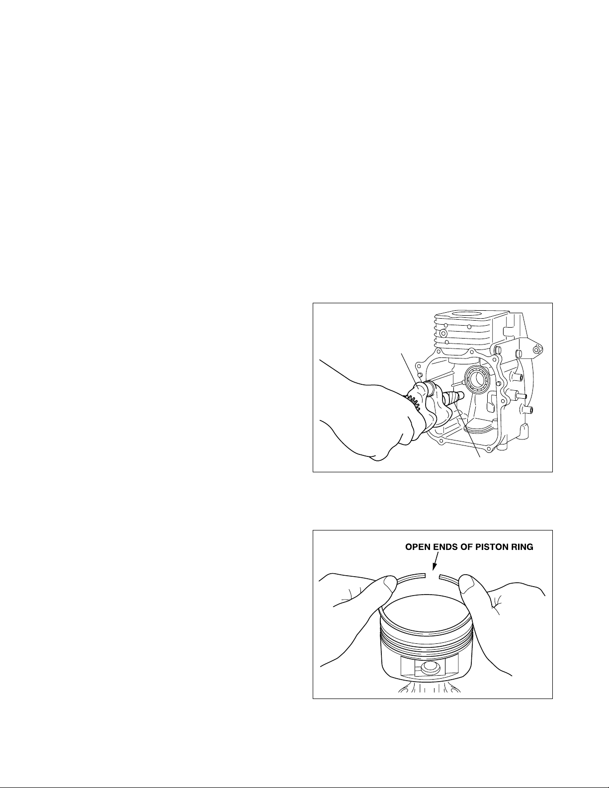
5-4-1 CRANKSHAFT
(1) Install crankshaft in crankcase wrapping the
keyway with pol y viny l ta pe to av oi d dam age
to oil seal.
(2) Install woodruff key for flywheel on crankshaft.
CRANKSHAFT
5-4-2 PISTON AND PISTON RINGS
(1) Install oil ring first, then second ring and top
ring.
Spread ring only far enough to slip over pis-
ton and into correct groove. Use care not to
distort ring.
Install second ring with punch ed mark bes ide
the gap face upward. (See Fig. 5-26a, 26b)
POLYVINYL TAPE
Fig. 5-23
OPEN ENDS OF PISTON RING
Fig. 5-24
-
30
-
Page 17
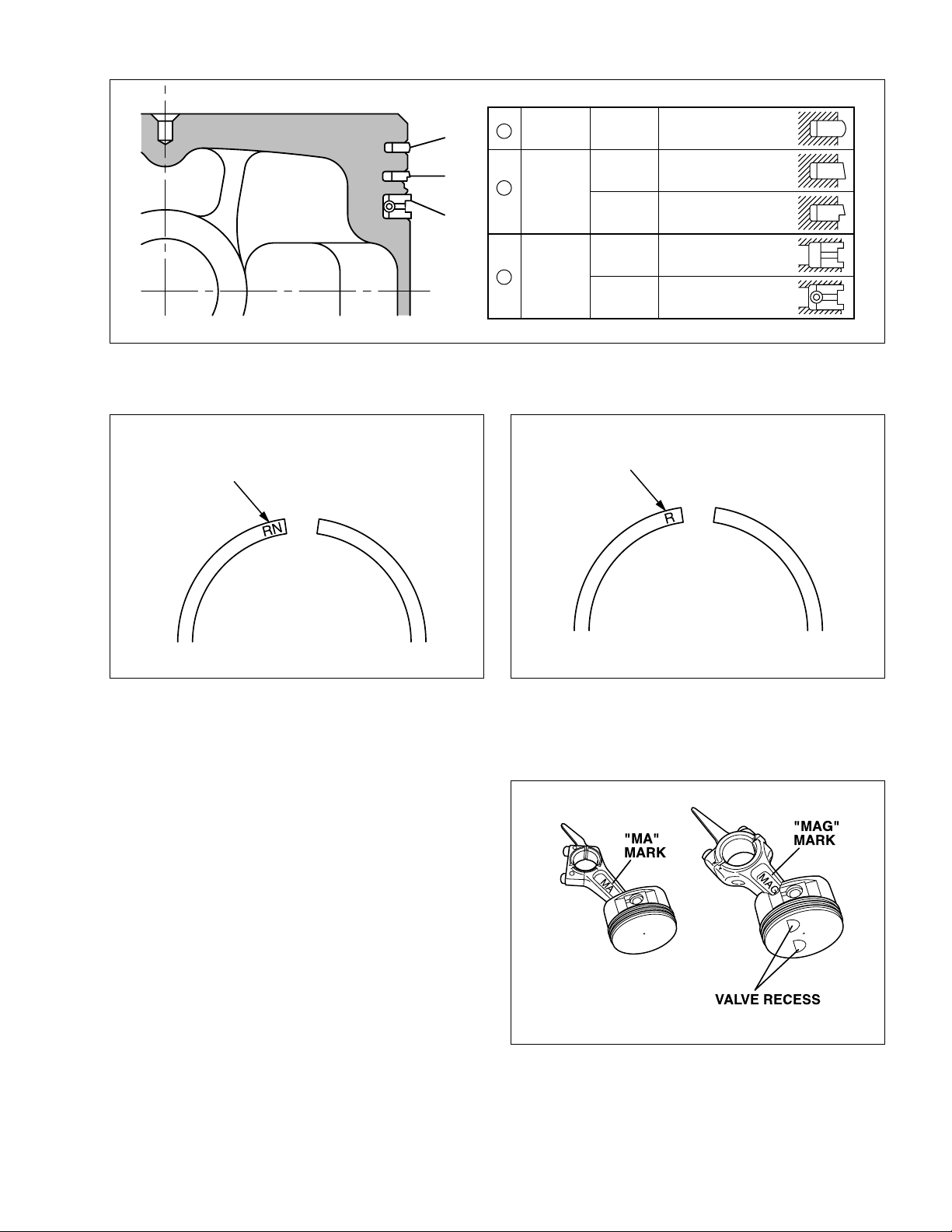
①
TOP
1
RING
EH09D
EH12-2D
BARREL
MARK "RN"
②
③
2
3
Fig. 5-25
SECOND
RING
OIL
RING
MARK "R"
EH09D
EH12-2D
EH09D
EH12-2D
TAPER
TAPER
UNDER CUT
CUTTER
CUTTER RING WITH
COIL EXPANDER
RING
Model: EH09D Model: EH12-2D
Fig. 5-26a
5-4-3 PISTON AND CONNECTING ROD
(1) EH09D
The direction of piston on connecting rod is
not specified.
EH12-2D
When installing the piston on the connecting
rod, place the valve recess of the piston crown
as shown in the illustration to the “MAG” side
of the connecting rod.
(2) Apply oil to the small end of connecting rod,
piston and piston pin before assembling.
Be sure to use clips on the both side of the
piston pin to secure piston pin in position.
"MA"
MARK
Model: EH09D
Fig. 5-26b
"MAG"
MARK
VALVE RECESS
Model: EH12-2D
Fig. 5-27
-
31
-
Page 18
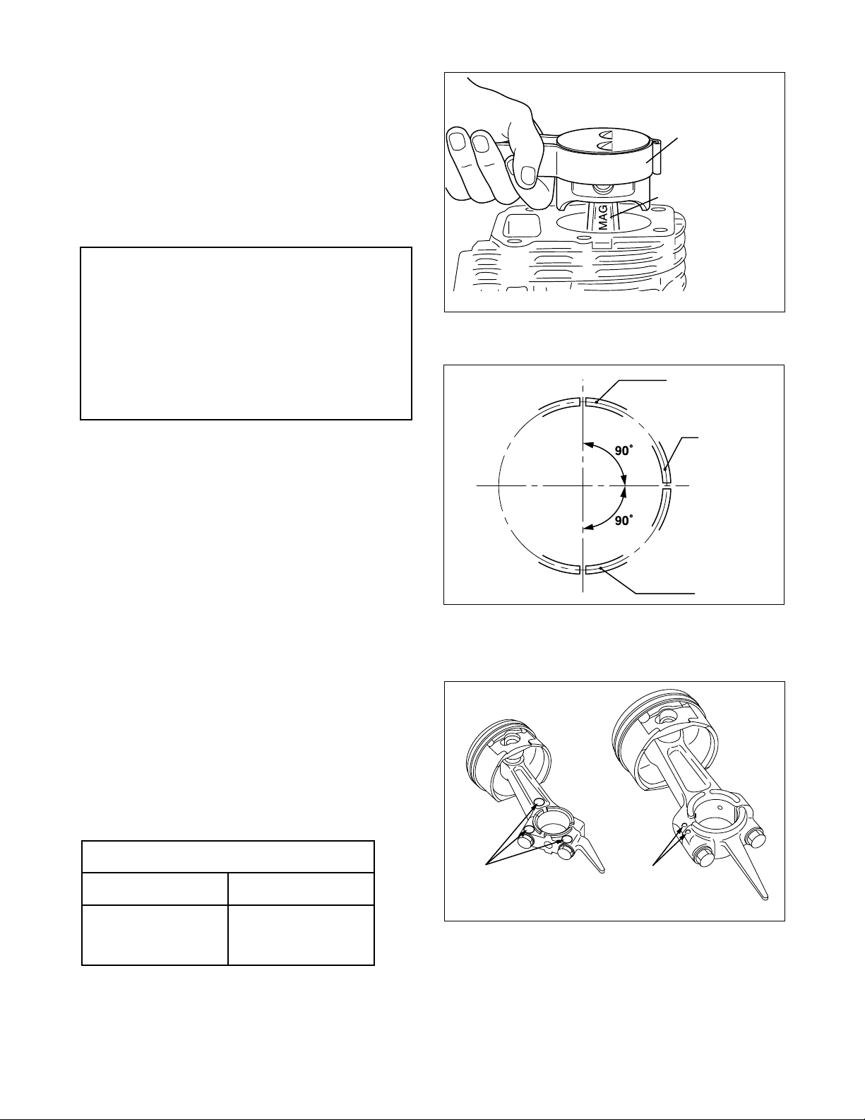
(3) Install piston and connecting rod assembly
into cylinder.
Use a piston ring compressor to hold piston
rings.
The “MA” mark (EH09D) ,“MAG” mark (EH12-
2D) of the connecting rod is to face the flywheel side of the engine when assembled.
Note:
PISTONRING
COMPRESSOR
CONNECTING ROD
("MA"SIDEEH09D)
("MAG"SIDE EH12-2D)
(1) Apply enough oil to lubricate the pis-
ton rings, connecting rod bearings
and cylinder bore before assembly.
(2) Set gaps of the piston rings 90 de-
grees apart from each other before
assembly.
5-4-4 CONNECTING ROD
(1) Turn crankshaft to bottom dead center, lightly
tap top of the piston until large end of the rod
meet crank pin.
(2) Install connecting rod cap to connecting rod.
Make sure to match the alignment marks on
the rod caps.
CRANKCASE (FLYWHEEL SIDE)
Fig. 5-28
SECOND RING
OIL RING
TOP RING
Fig. 5-29
Torque connecting rod bolts to specification.
M5 x 25 mm connecting rod bolt : 2 pcs. (EH09D)
M6 x 34 mm connecting rod bolt : 2 pcs. (EH12-2D)
euqrotgninethgiT
D90HED2-21HE
N8.7-9.5 ・m
gk08-06( ・ )mc
tf7.5-3.4( ・ ).bl
N11-8.8 ・m
gk511-09( ・ )mc
tf3.8-5.6( ・ ).bl
(3) Check for free movement of connecting rod
by turning crankshaft slowly.
-
32
-
ALIGNMENT
MARK
Model: EH09D Model: EH12-2D
ALIGNMENT
MARK
Fig. 5-30
Page 19

5-4-5 TAPPETS AND CAMSHAFT
G
(1) Oil the tappets and install them.
Push in fully to avoid damage during camshaft
installation.
(2) Lubricate bearing surfaces of camshaft.
Align the timing mark on crankshaft gear with
the timing mark on camshaft and install camshaft in the crankcase. (See Fig. 5-31a)
CAUTION :
Incorrect valve timing will cause mal-
function of the engine.
5-4-6 ADJUST CRANKSHAFT END PLAY
TIMING MARK
CRANKSHAFT
EAR
CAMSHAFT
Fig. 5-31a
(1) Adjust end play to 0.2 mm (0.008") using the
proper spacer.
The proper spacer may be determined in the
following manner.
1) Measure the height “A” (From the mating
surface to the inner race of the ball bearing.)
2) Measure the depth “B” (From the mating
surface to the crank gear.)
B-A = SIDE CLEARANCE (mm)
(SIDE CLEARANCE)-0.2 mm = THICKNESS OF CRANKSHAFT SHIM (mm)
B-A = SIDE CLEARANCE (in.)
(SIDE CLEARANCE)-0.008 in.= THICKNESS OF CRANKSHAFT SHIM (in.)
Following are available spacer shims.
TFAHSKNARC
).ni420.0(mm6.0=T
SMIHSRECAPS
Table. 5-1
).ni130.0(mm8.0=T
).ni930.0(mm0.1=T
Fig. 5-31b
-
33
-
Page 20

(2) Lubricate the oil seal and bearing surfaces.
Coat the surface of the main bearing cover with sealant (Three bond 1216).
Place spacer chosen in step (1) on crankshaft.
Use an oil seal guide when installing the main bearing cover to avoid damaging the oil seal .
Tap the cover into place with a soft hammer.
Main bearing cover EH09D M6 x 30 mm bolt and washer : 9 pcs.
EH12-2D M6 x 30 mm bolt and washer : 8 pcs.
euqrotgninethgiT
D2-21HE,D90HE
N8.11-8.9 ・m
gk021-001( ・ )mc
tf7.8-2.7( ・ ).bl
EH09D
M6 x 30 BOLT AND
WASHER AY : 9 pcs.
EH12-2D
SPACER
SEALANT
(
Three bond 1216
MAIN BEARING COVER CP
SPACER
CRANKSHAFT
MAIN BEARING
COVER CP
)
CAMSHAFT
CRANKCASE
SEALANT
(
Three bond 1216
)
M6 x 30 BOLT AND
WASHER AY : 8 pcs.
Fig. 5-32
-
34
-
CRANKSHAFT
CAMSHAFT
CRANKCASE
Page 21

5-4-7 CYLINDER HEAD
(1) Clean carbon and gum deposits from the valves, seats, ports and guides. Inspect valves, valve seats
and valve guides.
(2) Replace valves that are badly burned, pitted or warped.
(3) When installing valves in cylinder head, oil the valve stems and insert them into valve guide.
Then place cylinder head on flat table, install valve spring and spring retainer.
(4) Valve guides should be replaced when valve stem clearance exceeds specifications (See “SERVICE
DATA”).
Draw valve guides out and press new guides in.
Refer to “SERVICE DATA” for clearance specifications.
After replacing valves and guides, lap valves in place until a uniform ring shows around the face of
the valve. Clean valves and wash cylinder head thoroughly.
(5) Install cylinder head onto cylinder with new head gasket.
Tighten four flange bolts evenly in three steps by the following tightening torque:
Cylinder head M8 x 55 mm bolt : 4 pcs. (EH09D)
)D90HE(euqrotgninethgiT
petsts1petsdn2petSlaniF
N0.5 ・m
gk05( ・ )mc
tf6.3( ・ ).bl
N8.9 ・m
gk001( ・ )mc
tf2.7( ・ ).bl
Cylinder head M8 x 65 mm bolt : 4 pcs. (EH12-2D)
)D2-21HE(euqrotgninethgiT
petsts1petsdn2petSlaniF
N0.5 ・m
gk05( ・ )mc
tf6.3( ・ ).bl
N8.9 ・m
gk001( ・ )mc
tf2.7( ・ ).bl
N6.02-6.81 ・m
gk012-091( ・ )mc
tf2.51-7.31( ・ ).bl
N0.62-0.32 ・m
gk072-032( ・ )mc
tf0.03-0.71( ・ ).bl
-
35
-
Page 22

5-4-8 ROCKER ARMS AND PUSH RODS
(1) Insert push rods into crankcase.
Put push rod tip in the hollow of tappet top.
Note:
An oil return slot is located next to the tappet boss. If you do not put the push rod in the
tappet properly, the push rods will fall into the crankcase.
Removal of the main bearing cover is necessary to get them out.
(2) Apply oil to rocker arms and assemble them to cylinder head using pivot bolt and nut.
M6 x 60 BOLT AND
WASHER AY : 4 pcs.
BOLT (PIVOT) : 2 pcs.
ROCKER ARM
COLLET
ROCKER COVER
SPRING RETAINER
VALVE SPRING
M8 x 55 FLANGE
BOLT : 4 pcs.
M6 NUT
: 2 pcs.
EXHAUST VALVE
GASKET
GASKET
GUIDE PLATE
CYLINDER
HEAD CP
INTAKE VALVE
PUSH ROD
Fig. 5-33
-
36
-
Page 23

5-4-9 VALVE CLEARANCE ADJUSTMENT
THICKNESS GAUGE
ROCKER ARM
BOLT
(
PIVOT
)
NUT
Note:
T emporally fit the flywheel in position for
easy operation.
(1) EH09D
Position the piston at the top dead center of
compression stroke by matching the alignment
mark of flywheel with the alignment mark of
crankcase.
EH12-2D
Position the piston at the top dead center of
compression stroke. The top dead center may
be obtained by placing the key slot on the
power take off shaft to 10 o’clock position. (See
Fig. 5-34b)
(2) Loosen the nut under the rocker arm and turn
the bolt (pivot) to adjust the clearance between
rocker arm and valve stem end.
Tighten the nut on rocker arm.
Valve clearance : 0.07 - 0.13 mm
(0.0028 - 0.0051 in.)
ALIGNMENT
MARKS
Model: EH09D
Fig. 5-34a
45°
Model: EH12-2D
Fig. 5-34b
FLYWHEEL
P.T.O
Note:
Check and adjust valve clearance while
engine is cold.
Check operation of valves by turning
crankshaft. Then recheck the valve clearance.
(3) Install rocker cover and gasket.
Rocker cover M6 x 25 mm bolt : 4 pcs.
Fig. 5-35
-
37
-
Page 24

5-4-10 SPARK PLUG
Install spark plug to cylinder head.
Spark plug : NGK BM6A, BMR6A (EH09)
: NGK B6ES, BR6ES (EH12-2D)
)D90HE(euqrotgninethgiT
gulpkrapsweNgninethgiteR
N7.41-8.11 ・m
gk051-021( ・ )mc
tf9.01-7.8( ・ ).bl
N5.42-6.22 ・m
gk052-032( ・ )mc
tf1.81-6.61( ・ ).bl
5-4-11 FLYWHEEL MAGNETO
(1) Put the woodruff key in the keyway of crank-
shaft. Wipe off oil and grease thoroughly from
the tapered portion of crankshaft and flywheel
center hole.
(2) Install the flywheel to crankshaft.
Tighten the flywheel nut with the starter pulley.
euqrotgninethgiT
gulpkrapsweNgninethgiteR
N7.41-8.11 ・m
gk051-021( ・ )mc
tf9.01-7.8( ・ ).bl
)D2-21HE(euqrotgninethgiT
N5.62-6.22 ・m
gk072-032( ・ )mc
tf5.91-6.61( ・ ).bl
D90HED2-21HE
N1.94-2.44 ・m
gk005-054( ・ )mc
tf2.63-5.23( ・ ).bl
N0.36-0.95 ・m
gk056-006( ・ )mc
tf0.74-0.34( ・ ).bl
Fig. 5-36
-
38
-
Page 25

5-4-12 IGNITION COIL
THICKNESS GAUGE
IGNITION
COIL
Install ignition coil to crankcase.
Pay attention the direction of ignition coil and the
location of code.
Adjust air gap between ignition coil and flywheel
using a thickness gauge and tighten bolts.
M6 x 25 mm bolt and washer : 2 pcs.
Air gap : 0.3 - 0.5 mm
(0.012 - 0.020 in.)
euqrotgninethgiT
N8.01-8.8 ・m
gk011-09( ・ )mc
tf0.8-5.6( ・ ).bl
IGNITION COIL
Model: EH09D
Fig. 5-37a
THICKNESS
GAUGE
5-4-13 INTAKE PIPE, INSULATOR (EH12-2D)
(1) Install the intake pipe to the cylinder head with
gasket.
M6 flange nut : 2pcs.
M6 x 40 mm bolt and washer : 1pce.
Tightening torque : 9.8 - 13.7 N・m
(100 - 140 kg・cm)
(7.2 - 10.1 ft・lb.)
Then put the gasket and insulator on the intake
pipe.
M6 NUT : 2 pcs.
GASKET
Model: EH12-2D
Fig. 5-37b
M6 x 40 BOLT
AND WASHER AY: 1 pce.
INTAKE
PIPE
Fig. 5-38
-
39
-
Page 26

5-4-14 GOVERNOR, SPEED CONTROL SYSTEM AND CARBURETOR
EH09D
(1) Install governor lever to governor shaft, then tighten the locking bolt temporarily.
(2) Install base plate to crankcase.
(3) Install speed control lever, friction washer, pivot bolt, etc. to base plate as shown in illustration.
(4) Hook governor spring to proper holes of governor lever and speed control lever. (See Fig. 5-40a)
(5) Install insulator and gaskets for carburetor to cylinder head.
(6) Install carburetor to cylinder head hooking governor rod to governor lever and throttle lever of carbu-
retor. Hook rod spring over governor rod.
(7) Attach air cleaner base to carburetor. Tighten two flange nuts and a bolt. Connect breather pipe from
rocker cover to cleaner base.
M6 x 8 FLANGE
BOLT : 2 pcs.
SPACER
SPEED CONTROL
LEVER AY
BASE
PLATE CP
GOVERNOR SHAFT
M6 BOLT AND
WASHER AY : 1 pce.
RETURN
SPRING
ROD SPRING
GOVERNOR LEVER
FRICTION WASHER
INSULATOR
GOVERNOR ROD
GOVERNOR SPRING
M6 PIVOT BOLT
: 1 pce.
GASKET (INSULATOR
CARBURETOR
)
Fig. 5-39a
-
40
-
Page 27

EH12-2D
(1) Install governor lever to governor shaft, then tighten the locking bolt temporarily.
(2) Install speed control lever, pivot bolt, etc. as shown in illustration.
(3) Hook governor spring to proper holes of governor lever and speed control lever. (See Fig. 5-40b)
(4) Install insulator and gaskets for carburetor to intake pipe.
(5) Install carburetor to intake pipe hooking governor rod to governor lever and throttle lever of carbure-
tor. Hook rod spring over governor rod.
(6) Attach air cleaner base to carburetor. Tighten two flange nuts and a bolt. Connect breather pipe from
rocker cover to cleaner base.
INSULATOR
CARBURETOR
ROD SPRING
WIRE BRACKET
GOVERNOR
LEVER
M6 BOLT AND
WASHER AY : 1 pce.
M6 x14 FLANGE BOLT : 1 pce.
Fig. 5-39b
GOVERNOR
ROD
GOVERNOR
SPRING
NUT
GASKET
(
INSULATOR
M6 PIVOT BOLT : 1 pce.
)
SPEED CONTROL LEVER
M6 x 12 FLANGE
BOLT : 1 pce.
PROTECTOR
M8 x 16 BOLT AND
WASHER AY : 1 pce.
-
41
-
Page 28

5-4-15 AIR CLEANER
Install the air cleaner gasket and the cleaner base
and tighten them with 2-M6 flange nuts.
Then install the element and the cleaner case.
5-4-16 ADJUST GOVERNOR SYSTEM
(1) Turn the speed control lever all the way toward the high speed position and fix it by tightening self lock
nut.
(2) Check that the governor lever is pulled by the governor spring and carburetor throttle valve is fully
open.
(3) Turn the governor shaft clockwise all the way using a screw driver, and tighten lock bolt to secure the
lever on the shaft.
(4) Loosen the self lock nut to allow the speed control lever to move freely.
GOVERNOR ROD SPRING
GOVERNOR
ROD
GOVERNOR
LEVER
GOVERNOR
GOVERNOR
SHAFT
Model: EH09D
Fig. 5-40a
SPRING
Normal hooking
position
SPEED CONTROL
LEVER
GOVERNOR
ROD SPRING
GOVERNOR
ROD
GOVERNOR
LEVER
Normal hooking
position
GOVERNOR
SPRING
SPEED CONTROL
LEVER
GOVERNOR
SHAFT
Model: EH12-2D
Fig. 5-40b
-
42
-
Page 29

5-4-17a CYLINDER BAFFLE, MUFFLER BRACKET and MUFFLER (EH09D)
(1) Temporarily install cylinder baffle, muffler
bracket and blower housing bracket 2 to the
cylinder head.
: M6 flange nut : 2 pcs.
Do not tighten the flange nut fully.
(2) Temporarily install muffler and gasket to cylin-
der head.
: M6 self lock nut : 2 pcs.
: M6 x 12 mm bolt and washer : 2 pcs.
(3) Finally, tighten the self lock nut etc. fully,
according to the following priority.
1 1
1 M6 self lock nut : 2 pcs.
1 1
2 2
2 M6 x 12 mm bolt and washer : 2 pcs.
2 2
3 3
3 M6 flange nut : 2 pcs.
3 3
M6 x 12 BOLT AND
2
WASHER AY : 2 pcs.
MUFFLER
MUFFLER CP
BRACKET CP
3
GASKET
(
MUFFLER
euqrotgninethgiT
N8.01-8.8 ・m
gk011-09( ・ )mc
tf0.8-5.6( ・ ).bl
M6 FLANGE NUT : 2 pcs.
BLOWER HOUSING
BRACKET CP 2
CYLINDER BAFFLE
)
M6 SELF LOCK
1
NUT : 2 pcs.
Fig. 5-41a
-
43
-
Page 30

5-4-17b HEAD COVER, MUFFLER BRACKET and MUFFLER (EH12-2D)
(1) Temporarily install head cover and muffler
bracket to cylinder head.
: M6 x 18 mm flange bolt : 2 pcs.
(2) Temporarily install muffler, gasket (muf fler) and
spacer (exhaust) to cylinder head.
: M8 self lock nut : 2 pcs.
: M8 x 16 mm bolt and washer : 4 pcs.
N5.62-5.22 ・m
(3) Finally, tighten the self lock nut etc. fully,
according to the following priority.
1 1
1 M8 self lock nut : 2 pcs.
1 1
2 2
2 M8 x 16 mm bolt and washer : 2 pcs.
2 2
3 3
3 M8 x 16 mm bolt and washer : 2 pcs.
3 3
4 4
4 M8 x 18 mm flange bolt : 2 pcs.
4 4
gk072-032( ・ )mc
tf5.91-5.61( ・ ).bl
N8.01-8.8 ・m
gk011-09( ・ )mc
tf0.8-5.6( ・ ).bl
)8M(euqrotgninethgiT
)6M(euqrotgninethgiT
M8 x 16 BOLT AND
2
WASHER AY : 2 pcs.
MUFFLER
M8 SELF LOCK
1
NUT : 2 pcs.
M8 WASHER : 2 pcs.
M8 x 16 BOLT AND
3
WASHER AY : 2 pcs.
M6 x 18 FLANGE
4
BOLT : 2 pcs.
Fig. 5-41b
GASKET
(
MUFFLER
)
A
SPACER
(
EXHAUST
A
)
MUFFLER BRACKET
HEAD COVER
-
44
-
Page 31

5-4-18 BLOWER HOUSING AND RECOIL STARTER
(1) Attach blower housing to crankcase. Tighten
five flange bolts.
M6 x 12 mm flange bolt : 5 pcs.
Insert the high tension cord from the ignition
coil into the notch of the blower housing so as
not to pinch the cord.
(2) Install recoil starter to blower housing.
M6 x 8 mm flange bolt : 4 pcs.
Note:
Be careful of pulling direction of starter
rope.
5-4-19 STOP SWITCH
(1) Install stop switch to blower housing.
(2) Connect wires referring to the wiring diagram.
-
End of the reassembly
-
CLAMP
STOP SWITCH
STOP SWITCH WIRE
Model: EH12-2D
Fig. 5-42
-
45
-
Page 32

5-5 BREAK-IN OPERATION
A new engine or an engine that has been completely overhauled by being fitted with a new piston, rings,
valves and connecting rod should be thoroughly RUN-IN before being put back into service.
Good bearing surfaces and running clearances between the various parts can only be established by
operating the engine under reduced speed and loads for a short period of time.
While the engine is being tested, check for oil leaks.
Make final carburetor adjustment and regulate the engine operating speed.
petSdaoLdeepSenignEemiT
1petS daoLoNmpr005,2.nim01
2petS daoLoNmpr000,3.nim01
3petS daoLoNmpr006,3.nim01
4petS
5petS
D90HE)PH0.1(Wk7.0
mpr006,3.nim03
D2-21HE)PH4.1(Wk0.1
D90HE)PH9.1(Wk4.1
mpr006,3.nim06
D2-21HE)PH8.2(Wk1.2
Table. 5-2
6. MAGNETO
6-1 OPERATION AND FUNCTION
The ignition system of the EH09D and EH12-2D is a breakerless flywheel magneto with an automatic
advancing system.
Being different from the breaker point type ignition system, this system is completely free from such
troubles as starting-up failure due to dirty, burnt or corroded point surface.
The electronic automatic advancing ensures extremely easy starts and stable high performance at operating speed by advancing the ignition timing to the most suitable point.
6-2 BASIC THEORY
(1) Revolution of the flywheel generates electricity on the primary side of the ignition coil, and the base
current I
Current I
1 flows to the power transistor.
1 turns the power transistor “ON” and the electric current I2 flows.
-
46
-
Page 33

(2) At lower engine revolution, when the flywheel reached the ignition point the low speed ignition timing
control circuit operates to run the base current I
current I
1 to bypass as current I4.
3 to turn the signal transistor A “ON” allowing the
At this moment the power transistor turns “OFF” and the current I
2 is abruptly shut off resulting in the
high voltage generated in the secondary coil which produces sparks at the spark plug.
(3) At higher engine revolution, the advancing control circuit operates at the ignition timing to run the
base current I
At this moment the power transistor turns “OFF” and the current I
5 to turn the signal transistor B “ON” allowing the current I1 to bypass as current I6.
2 is abruptly shut off resulting in the
high voltage generated in the secondary coil which produces sparks at the spark plug.
The operating timing of the advancing control circuit advances in accordance with the increase of
engine speed resulting in the advancing of ignition timing as shown in Fig. 6-1(b).
I1
Power Transistor
Primary Coil
Secondary Coil
Spark plug
I2
Signal Transistor B
Low Speed
Ignition
Timing
Control Circuit
Resister
I3
Signal Transistor A
Automatic
Advancing
Control
Circuit
I5
I4
I6
Fig. 6-1a
(
B.T.D.C.
IGNITION TIMING
23°
18°
15°
-
)
500 1000 2000 3000
47
-
ELECTRONIC ADVANCING FLYWHEEL
MAGNETO SYSTEM
STEP ADVANCING
ENGINE REVOLUTION
Fig. 6-1b
(
EH12-2D
(
EH09D
(r.p.m.)
)
)
Page 34

6-3 WIRING DIAGRAM
● STANDARD
Fig. 6-2
-
48
-
Page 35

7. AUTOMATIC DECOMPRESSION SYSTEM
EH09D and EH12-2D engines employ an automatic decompression system as a standard feature. This
enables easy starting of the engine, with lighter recoil pull.
The automatic decompression system releases the compression of the engine by lifting up the exhaust
valve at cranking speeds. The following is the explanation of how the system works.
At the end of the compression process, the release lever lifts up the tappet which in turns opens up the
exhaust valve slightly to release the compression. The release lever has a flyweight on its end and
another end of the lever is a crescent cam.
When the engine is cranked, the crescent cam projects above the cam profile and lifts up the tappet
because the gravity force on the weight is larger than the centrifugal force on the weight.
TAPPET
FLYWEIGHT
CRESCENT CAM
RELEASE LEVER
EXHAUST CAM
ROTATION
EXHAUST CAM
CAMSHAFT
Fig. 7-1
When the cranking speed reaches a specified r.p.m., the crescent cam is retracted under the cam profile
because the centrifugal force applied to the flyweight becomes larger than the force of gravity on the
weight and thus it is shifted to the position shown in the illustration below.
FLYWEIGHT
TAPPET
RELEASE LEVER
CRESCENT CAM
EXHAUST CAM
ROTATION
EXHAUST CAM
CAMSHAFT
Fig. 7-2
-
49
-
Page 36

8a. FLOAT TYPE CARBURETOR (EH09D)
8a-1 OPERATION AND CONSTRUCTION
8a-1-1 FLOAT SYSTEM
The float chamber is located below the carburetor body and, with a float and a needle valve,
maintains a constant fuel level during engine operation.
The fuel flows from the fuel tank into the float
chamber through the needle valve. When the fuel
rises to a specific level, the float rises, and when
its buoyancy and fuel pressure are balanced, the
needle valve closes to shut off the fuel, thereby
keeping the fuel at the predetermined level.
FLOAT
FUEL
NEEDLE VALVE
Fig. 8-1
BY-PASS
PILOT OUTLET
PILOT JET
PILOT AIR JET
MAIN NOZZLE
CHOKE
AIR
INTAKE
FLOAT
MAIN AIR JET
MAIN JET
Fig. 8-2
-
50
-
Page 37

8a-1-2 PILOT SYSTEM
The pilot system feeds the fuel to the engine during idling and low-speed operation. The fuel is fed
through the main jet to the pilot jet, where it is metered, and mixed with the air metered by the pilot air jet.
The fuel-air mixture is fed to the engine through the pilot outlet and the bypass. At idling speed, the fuel
is mainly fed from the pilot outlet.
8a-1-3 MAIN SYSTEM
The main system feeds the fuel to the engine at medium and high-speed operation. The fuel is metered
by the main jet and fed to the main nozzle. The air metered by the main air jet is mixed with the fuel
through the bleed holes in the main nozzle, and the mixture is atomized out of the main bore. It is mixed
again with the air taken through the air cleaner into an optimum fuel-air mixture, which is supplied to the
engine.
8a-1-4 CHOKE
The choke is used for easy starting when the engine is cold. When the starter is operated with a closed
choke, the negative pressure applied to the main nozzle increases and draws more fuel ; thus richening
the mixture and making starting the engine easier.
8a-2 DISASSEMBLY AND REASSEMBLY
Apart from mechanical failures, most of carburetor troubles are caused by an incorrect mixing
ratio, which may arise mainly due to a clogged up
air or fuel passage in jets, or fuel level variations.
In order to assure proper flow of air and fuel, the
carburetor must be kept clean at all times. The
carburetor disassembly and reassembly procedures are as follows.
8a-2-1 THROTTLE SYSTEM
(1) The spring
the throttle stop screw
(2) Remove the philips screw
ww
w, and pull out the throttle shaft
ww
*Be careful not to damage throttle valve rim.
rr
r can be taken out by removing
rr
tt
t.
tt
qq
q and throttle valve
qq
ee
e.
ee
1
12
15
17
11
3 4 5 62
789
13
16
19
18
14
10
Fig. 8-3
-
51
-
Page 38

8a-2-2 CHOKE SYSTEM
(1) Remove the philips screws
(2) When reassembling the choke shaft, make sure that the cutout in the choke valve faces the pilot air
jet.
yy
y and choke valve
yy
uu
u, and pull out the choke shaft
uu
ii
i.
ii
8a-2-3 PILOT SYSTEM
(1) Remove the pilot jet
(2) Reassembly
Tighten the pilot jet securely. Otherwise, the fuel may leak, causing engine malfunction.
oo
o, using correct tool to avoid damage to it.
oo
8a-2-4 MAIN SYSTEM
(1) Remove the bolt
(2) Remove the main jet
(3) Reassembly
a) Fasten the main jet securely to the body. Otherwise, the fuel may become too rich and cause
engine malfunction.
!0!0
!0 and take out float chamber body
!0!0
!3!3
!3 and guide holder from the body
!3!3
!1!1
!1.
!1!1
!2!2
!2 .
!2!2
b) The bolt
!1!1
!1.
!1!1
!0!0
!0 tightening torque is 90 kg-cm. Be sure to set the gasket
!0!0
!5!5
!5 and washer
!5!5
8a-2-5 FLOAT SYSTEM
(1) Pull out the float pin
needle valve needs to be replaced, replace it with rubber needle.
CAUTION :
When cleaning the jets, use neither a drill nor a wire (because of possible damage of the
orifice which will adversely affect fuel flow). Be sure to use compressed air to blow them
clean.
(2) When removing the needle valve and float, gently tap the reverse side of the float pin
more slender than the float pin and remove, since the float pin is pressed into the carburetor body.
!6!6
!6 and remove the float
!6!6
!7!7
!7 and then remove the clip
!7!7
!8!8
!8 and needle valve
!8!8
!4!4
!4 for chamber
!4!4
!9!9
!9. If the
!9!9
!6!6
!6 using a rod
!6!6
-
52
-
Page 39

8b. FLOAT TYPE CARBURETOR (EH12-2D)
PILOT OUTLET
BY-PASS
PILOT AIR JET
CHOKE
AIR
INTAKE
MAIN AIR JET
MAIN NOZZLE
FLOAT
NEEDLE VALVE
FUEL
PILOT JET
FLOAT
MAIN JET
8b-1 OPERATION AND CONSTRUCTION
8b-1-1 FLOAT SYSTEM
The float chamber is located below the carburetor body and, with a float and a needle valve,
maintains a constant fuel level during engine operation.
The fuel flows from the fuel tank into the float
chamber through the needle valve. When the fuel
rises to a specific level, the float rises, and when
its buoyancy and fuel pressure are balanced, the
needle valve closes to shut off the fuel, thereby
keeping the fuel at the predetermined level.
Fig. 8-4
Fig. 8-5
-
53
-
Page 40

8b-1-2 PILOT SYSTEM
The pilot system feeds the fuel to the engine during idling and low-speed operation.
The fuel is fed through the main jet to the pilot jet, where it is metered, and mixed with the air metered by
the pilot air jet. The fuel-air mixture is fed to the engine through the pilot outlet and the bypass. At idling
speed, the fuel is mainly fed from the pilot outlet.
8b-1-3 MAIN SYSTEM
The main system feeds the fuel to the engine at medium and high-speed operation. The fuel is metered
by the main jet and fed to the main nozzle. The air metered by the main air jet is mixed with the fuel
through the bleed holes in the main nozzle, and the mixture is atomized out of the main bore. It is mixed
again with the air taken through the air cleaner into an optimum fuel-air mixture, which is supplied to the
engine.
8b-1-4 CHOKE
The choke is used for easy starting when the engine is cold. When the starter is operated with a closed
choke, the negative pressure applied to the main nozzle increases and draws more fuel ; thus richening
the mixture and making starting the engine easier.
8b-2 DISASSEMBLY AND REASSEMBLY
Apart from mechanical failures, most of carburetor troubles are caused by an incorrect mixing
ratio, which may arise mainly due to a clogged up
air or fuel passage in jets, or fuel level variations.
In order to assure proper flow of air and fuel, the
carburetor must be kept clean at all times. The
carburetor disassembly and reassembly procedures are as follows.
8b-2-1 THROTTLE SYSTEM
(1) Remove the philips screw
ww
w, and pull out the throttle shaft
ww
(2) The spring
the throttle stop screw
*Be careful not to damage throttle valve rim.
rr
r can be taken out by removing
rr
qq
q and throttle valve
qq
ee
e.
ee
tt
t.
tt
Fig. 8-6
-
54
-
Page 41

(2) Setting the attachments off (Fig. 9-2)
-1 : Fix the case and loosen the set-screw.
-2 : Put off the set-screw, the ratchet guide,
the friction spring and the ratchet in the
same order from above.
(3) Setting the reel off (Fig. 9-2)
-1 : Push the reel lightly so that it will not float
up. Move the reel clockwise and counterclockwise about a quarter circle for several times until it moves smoothly.
-2 : Pull up the reel gradually and slowly and
put it off from the case.
-3 : In case the spring in the reel is close to
pop up, redo the steps of (3)-1 and (3)-2
again.
SET SCREW
RATCHET
GUIDE
FRICTION
SPRING
RATCHET
REEL
STARTER
CASE
WARNING :
Do not drop or shake the reel and put it
on a level table because there is a spring
set in the disassembled reel.
Disassembly is complete.
WARNING :
Before starting the assembly, make sure to wear the protective glasses.
9-1-2 Assembly Steps
(1) Setting the reel into the case.
-1 : Paste grease on the case. (Fig. 9-3)
-2 : Adjust the position of the inner end of the
spring, which is set in the reel. (Fig. 9-4)
Fig. 9-2
GREASE PASTING
-3 : Hold the reel so that the shaft/hook part
and the inner-end of the spring are hooked
together. Drop the reel gently from above
into the case.
-4 : Move the reel slightly counterclockwise and
make sure the spring is hooked.
-
63
SHAFT / HOOK PARTS
Fig. 9-3
THE POSITION THE END TOUCHES
THE RIB OF THE BEARING
Fig. 9-4
-
Page 42

(2) Setting the attachments
-1: Set the ratchet into the reel. (Fig. 9-5)
THE RATCHET IS KEPT AT CLOSE-POSITION
Fig. 9-5
-2: Holding the ratchet, set the ratchet-guide
subassembly. (Fig. 9-6)
(3) Tightening the set-screw.
-1 : Push the ratchet-guide lightly by hand so
that the ratchet guide won't move and
tighten the set-screw.
SET SCREW
RATCHET
GUIDE
FRICTION
SPRING
RATCHET GUIDE SUB-ASSEMBLY
Fig. 9-6
ABOUT 200mm
FROM THE REEL
(4) Storing the spring-power.
-1 : Hold the case tight and using both hands,
wind up the reel counterclockwise 6 times.
-2 : Set the reel to keep the position, whereby
the rope hole of the reel and the rope guide
make a direct line. (Fig. 9-7)
Fig. 9-7
WARNING :
The spring power is at its most when the reel is being wound. Therefore, do not abruptly
put off your hand nor loosen the pressure of Your finger unintentionally.
-
64
-
Page 43

(5) Setting the rope. (2 persons required)
-1 : Set the end of the rope through the rope
guide and the rope hole of the reel and pull
the end about 20 cm out of the reel.
(Fig. 9-7)
-2 : Fasten the end of the rope.
-3 : Put the rope into the reel, whereby make
sure that the rope will not float up.
(Fig. 9-9)
-4 : Hold the rope firmly with one hand at the
position about 50 cm from the rope guide
and keep the rope slightly pulled so that
the rope will not be wound in.
ABOUT
20mm
Fig. 9-8
-5 : Take your hand off the reel gently and release the rope slowly checking the winding power of the spring until the knob
reaches the rope guide.
Fig. 9-9
Assembly is complete.
(6) Test the operation of the recoil starter to see if the rope recoils satisfactorily and the ratchets extend
and retract properly. Mount the recoil starter to the engine.
(7) If the spring escapes from the reel when disassembling the recoil, hook the outer end of the spring
onto the notch of the reel and rewind the spring into the housing.
(8) Lubricate the rotating parts, sliding parts and spring with heat resistant grease before reassembling
the recoil and prior to long term storage.
-
65
-
Page 44

10. TROUBLESHOOTING
The following three conditions must be fulfilled for satisfactory engine start.
1. The cylinder filled with a proper fuel-air mixture.
2. Good compression in the cylinder.
3. Good spark, properly timed, to ignite the mixture.
The engine cannot be started unless these three conditions are met. There are also other factors which
make engine start difficult, e. g., a heavy load on the engine when it is about to start at low speed, and a
high back pressure due to a long exhaust pipe.
The most common causes of engine troubles are given below :
10-1 STARTING DIFFICULTIES
10-1-1 FUEL SYSTEM
(1) No gasoline in the fuel tank, or the fuel cock closed.
(2) The carburetor is not choked sufficiently especially when the engine is cold.
(3) Water, dust or gum in the gasoline interfering with the fuel flow to the carburetor.
(4) Inferior grade gasoline or poor quality gasoline not vaporized enough to produce the correct fuel-air
mixture.
(5) The carburetor needle valve is held open by dirt or gum. This trouble can be detected as the fuel flows
out of the carburetor when the engine is idling. (Overflow)
This trouble may be remedied by lightly tapping the float chamber with the grip of a screwdriver or the
like.
(6) If the carburetor overflows, excessive fuel runs into the cylinder when starting the engine, making the
fuel-air mixture too rich to burn. If this happens, remove the spark plug, and turn the starting pulley a
few turns in order to let the rich fuel-air mixture out of the spark plug hole and into the atmosphere.
Keep the choke valve open during this operation.
Dry the spark plug well, screw it into place, and try to start again.
10-1-2 COMPRESSION SYSTEM
If starting difficulties and loss of power are not due to the fuel system or ignition system, the followings
must be checked for possible lack of compression.
(1) Engine inside is completely dried up because of a long period of storage.
(2) Loose or broken spark plug. This causes a hissing noise made by air/fuel mixture running out of
cylinder in compression stroke during cranking.
(3) Damaged head gasket or loose cylinder head. A similar hissing noise is produced during compres-
sion stroke.
-
66
-
Page 45

(4) Incorrect Valve clearance
If the correct compression is not obtained even after remedying the above, disassemble the engine
and check further as follows :
a) Valve stuck open due to carbon or gum on the valve stem.
b) If the piston rings are stuck on the piston, remove the piston and connecting rod from the engine.
Clean or replace the parts.
10-1-3 IGNITION SYSTEM
Check the followings for lack of sparks.
(1) Wires of the ignition coil, spark plug or contact breaker disconnected.
(2) Ignition coil damaged and shorted.
(3) Spark plug cable wet or soaked with oil.
(4) Spark plug dirty or wet.
(5) Spark plug electrode gap incorrect.
(6) Spark plug electrodes are connected or bridged.
(7) Incorrect spark timing.
(8) Proper connection of all wires.
10-2 ENGINE MISFIRES
(1) Incorrect spark plug electrode gap. Adjust it to anywhere between 0.7 and 0.8 mm.
(2) Ignition cable worn and leaking.
(3) Sparks weak.
(4) Ignition wire connections loose.
(5) Water in gasoline.
(6) Insufficient compression.
10-3 ENGINE STOPS
(1) Fuel tank empty. Water, dirt, gum, etc. in gasoline.
(2) Vapor lock, i. e., gasoline evaporating in the fuel lines due to overheating of the engine.
(3) Vapor lock in the fuel lines or carburetor due to the use of too volatile (winter) gas in the hot season.
(4) Air vent hole in the fuel tank cap plugged.
(5) Bearing parts seized due to lack of oil.
(6) Magneto or ignition coil faulty.
-
67
-
Page 46

10-4 ENGINE OVERHEATS
(1) Crankcase oil level low. Add oil immediately.
(2) Spark timing incorrect.
(3) Low grade gasoline is used, or engine is overloaded.
(4) Cooling air circulation restricted.
(5) Cooling air path misdirected causing loss of cooling efficiency.
(6) Cylinder head cooling fins clogged up with dirt.
(7) Engine operated in an enclosed space without sufficient cooling air.
(8) Exhaust gas discharge restricted, or carbon deposits in the combustion chamber.
(9) Engine running on low-octane gasoline detonates due to heavy load at low speed.
10-5 ENGINE KNOCKS
(1) Poor quality gasoline.
(2) Engine operating under heavy load at low speed.
(3) Carbon or lead deposits in the cylinder head.
(4) Spark timing incorrect.
(5) Loose connecting rod bearing due to wear.
(6) Loose piston pin due to wear.
(7) See causes of engine overheat.
10-6 ENGINE BACKFIRES THROUGH CARBURETOR
(1) Water or dirt in gasoline, or low-grade gasoline.
(2) Intake valve stuck.
(3) Valves overheated, or hot carbon particles in the combustion chamber.
(4) Engine cold.
-
68
-
Page 47

11. INSTALLATION
Engine life, ease of maintenance and inspection, frequency of checks and repairs, and operating cost all
depend on the way in which the engine is installed. Review the following instructions carefully for installing the engine.
11-1 INSTALLING
When mounting the engine, carefully examine its position, the method of connecting it to a machine, the
foundation, and the method of supporting the engine.
When determining its mounting position, in particular, make sure that gasoline and oil can easily be
supplied and checked, the spark plug can easily be checked, the air cleaner can easily be serviced, and
that the oil can easily be discharged.
11-2 VENTILATION
Fresh air is necessary for cooling the engine and burning the fuel.
In the case the engine is operated under a hood or in a small room, temperature rise in the engine room
can cause vapor lock, oil deterioration, increased oil consumption, loss of power, piston seizure, shorter
engine life, etc., making it impossible to operate the engine properly . It is necessary, therefore, to provide
a duct or baffle to guide cooling air to the engine to prevent recirculation of the hot air used for engine
cooling, and temperature rise of the machine. Keep the engine room temperature below 50°C even in the
hottest period of the year.
11-3 EXHAUST GAS DISCHARGE
Exhaust gas is noxious. When operating the engine indoors, be sure to discharge the exhaust gas
outdoors. If a long exhaust pipe is used in such a case, the internal resistance increases causing loss of
engine power. Thus pipe inside diameter must be increased in proportion to exhaust pipe length.
Exhaust pipe : Less than 3 m long, pipe inside diameter 30 mm ,
Less than 5 m long, pipe inside diameter 33 mm.
11-4 POWER TRANSMISSION TO DRIVEN MACHINES
11-4-1 BELT DRIVE
Take the following notes into consideration.
* V-belts are preferable to flat belts.
* The driving shaft of the engine must be parallel to the driven shaft of the machine.
* The driving pulley of the engine must be in line with the driven pulley of the machine.
* Install the engine pulley as close to the engine as possible.
* If possible, span the belt horizontally.
* Disengage the load when starting the engine.
If no clutch is used, use a belt tension pulley or the like.
11-4-2 FLEXIBLE COUPLING
When using a flexible coupling, run out and misalignment between the driven shaft and engine shaft
must be minimized. Run out and misalignment tolerance are specified by the coupling manufacturer.
-
69
-
Page 48

12. SERVICE DATA
“STD” in the following table is the parts dimension from the brand new engine or the spare parts.
Whereas, “Limit” shows the maximum allowance for the parts to be used on the engine.
If the measurement exceeds beyond the “Limit”, the part needs to be replaced and/or repaired.
12-1 CLEARANCE DATA AND LIMITS
METI
DAEHREDNILYC
ssentalF*
htdiwtcatnoctaesevlaV*
.aidedisniediugevlaV*
Unit : mm (in.)
D90HE
DTStimiL
NAHTSSEL
50.0
)200.0(
.XE.NI
1.1-8.0
)3340.0-5130.0(
815.5-005.5
)2712.0-5612.0(
1.0
)400.0(
0.2
)970.0(
56.5
)4222.0(
Unit : mm (in.)
D2-21HE
METI
DTStimiL
DAEHREDNILYC
ssentalF*
NAHTSSEL
50.0
)200.0(
htdiwtcatnoctaesevlaV*
.XE.NI
0.1-7.0
)930.0-820.0(
.aidedisniediugevlaV*
815.5-005.5
)2712.0-5612.0(
1.0
)400.0(
0.2
)970.0(
56.5
)4222.0(
-
70
-
Page 49

Unit : mm (in.)
D90HED2-21HE
METI
DTStimiLDTStimiL
REDNILYC
.aidedisnI*
DTS
ts1
gnirober
ts2
gnirober
910.15-0.15
)900.2-800.2(
962.15-052.15
)5810.2-7710.2(
915.15-005.15
)3820.2-6720.2(
derobereboT
ehtnehw
ecnereffid
.xamneewteb
.nimdna
retemaidfo
1.0otdehcaer
.)400.0(
ottiD
--------------------
910.06-000.06
)0363.2-2263.2(
962.06-052.06
)8273.2-0273.2(
915.06-005.06
)6283.2-9183.2(
derobereboT
ehtnehw
ecnereffid
.xamneewteb
.nimdna
retemaidfo
1.0otdehcaer
.)400.0(
ottiD
--------------------
.gniroberretfassenidnuoR*
NAHTSSEL
10.0
)400.0(
--------------------
NAHTSSEL
10.0
)400.0(
--------------------
.gniroberretfayticirdnilyC*
NAHTSSEL
510.0
)6000.0(
--------------------
NAHTSSEL
510.0
)6000.0(
--------------------
NOTSIP
tsurhtnitrikstA(ezisnotsiP*
)noitcerid
DTS
s/ots1
s/odn2
99.05-79.05
)5700.2-7600.2(
42.15-22.15
)3710.2-5610.2(
94.15-74.15
)2720.2-4620.2(
88.05
)1300.2(
31.15
)3210.2(
83.15
)8220.2(
89.95-69.95
)4163.2-6063.2(
32.06-12.06
)3173.2-5073.2(
84.06-64.06
)1183.2-3083.2(
78.95
)1753.2(
21.06
)9663.2(
73.06
)8673.2(
-
71
-
Page 50

Unit : mm (in.)
D90HED2-21HE
METI
DTStimiLDTStimiL
NOTSIP
ecnaraelcedisevoorggniR*
poT
dn2
gnirliO
080.0-530.0
)1300.0-4100.0(
080.0-530.0
)1300.0-4100.0(
560.0-010.0
)6200.0-4000.0(
51.0
)600.0(
51.0
)600.0(
51.0
)600.0(
570.0-030.0
)0300.0-2100.0(
570.0-030.0
)0300.0-2100.0(
570.0-020.0
)0300.0-8000.0(
51.0
)600.0(
51.0
)600.0(
51.0
)600.0(
elohnipnotsiP*
900.11-199.01
)4334.0-7234.0(
530.11
)4434.0(
200.31-199.21
)9115.0-5115.0(
530.31
)2315.0(
.aidedistuonipnotsiP*
000.11-299.01
)1334.0-8234.0(
069.01
)5134.0(
000.31-299.21
)8115.0-5115.0(
069.21
)2015.0(
dnanotsipneewtebecnaraelC*
trikstarednilyc
.aera
940.0-010.0
)9100.0-4000.0(
pagdnegnirnotsiP*
poT
dn2
gnirliO
poT
53.0-51.0
)410.0-600.0(
dn2
55.0-53.0
)220.0-410.0(
52.0-50.0
)010.0-200.0(
52.0
)010.0(
5.1
)1950.0(
5.1
)1950.0(
470.0-510.0
)9200.0-6000.0(
4.0-2.0
)610.0-800.0(
4.0-2.0
)610.0-800.0(
52.0
)010.0(
5.1
)1950.0(
5.1
)1950.0(
-
72
-
Page 51

Unit : mm (in.)
D90HED2-21HE
METI
DTStimiLDTStimiL
DORGNITCENNOC
.aidedisnidnegiB*
310.02-000.02
)9787.0-4787.0(
dnegibneewtebecnaraelC*
nipknarcdna
1.02
)3197.0(
310.62-000.62
)1420.1-6320.1(
1.62
)6720.1(
360.0-730.0
)5200.0-5100.0(
2.0
)800.0(
640.0-020.0
)8100.0-8000.0(
2.0
)800.0(
.aidedisnidnellamS*
120.11-010.11
)9334.0-5334.0(
80.11
)2634.0(
120.31-010.31
)6215.0-2215.0(
80.31
)0515.0(
llamsneewtebecnaraelC*
nipnotsipdnadne
920.0-010.0
)1100.0-4000.0(
21.0
)7400.0(
920.0-010.0
)1100.0-4000.0(
21.0
)7400.0(
ecnaraelcedisdnegiB*
7.0-1.0
)820.0-400.0(
0.1
)040.0(
7.0-1.0
)820.0-400.0(
0.1
)040.0(
TFAHSKNARC
.aidedistuonipknarC*
369.91-059.91
)9587.0-4587.0(
58.91
)5187.0(
089.52-769.52
)8220.1-3220.1(
58.52
)7710.1(
.aidlanruoJ*
D1 D2
2D,1D
799.91-889.91
)3787.0-9687.0(
-
73
-
2D,1D
799.42-889.42
)1489.0-9389.0(
Page 52

Unit : mm (in)
D90HED2-21HE
METI
DTStimiLDTStimiL
TFAHSMAC
).XEdna.NI(thgiehmaC*
5.81-3.81
)827.0-027.0(
51.81
)517.0(
8.92-6.92
)371.1-561.1(
54.92
)951.1(
.aidedistuolanruoJ*
epyt"D"
D
1
D
1
D
2
D
2
789.9-279.9
)2393.0-6293.0(
789.9-279.9
)2393.0-6293.0(
59.9
)7193.0(
59.9
)7193.0(
489.61-379.61
)7866.0-2866.0(
489.41-379.41
)9985.0-5985.0(
59.61
)3766.0(
59.41
)6885.0(
EVLAV
.aidedistuometsevlaV*
.NI
.XE
554.5-044.5
)8412.0-2412.0(
444.5-624.5
)3412.0-6312.0(
53.5
)6012.0(
53.5
)6012.0(
554.5-044.5
)8412.0-2412.0(
444.5-624.5
)3412.0-6312.0(
53.5
)6012.0(
53.5
)6012.0(
metsevlavneewtebecnaraelC*
evlavdna.aid
.ediug
.NI
.XE
870.0-540.0
)1300.0-8100.0(
290.0-650.0
)6300.0-2200.0(
3.0
)210.0(
3.0
)210.0(
870.0-540.0
)1300.0-8100.0(
290.0-650.0
)6300.0-2200.0(
3.0
)210.0(
3.0
)210.0(
ecnaraelcevlaV*
.XE/.NI
)dloc(
-
74
31.0-70.0
)1500.0-8200.0(
31.0-70.0
)1500.0-8200.0(
-
Page 53

Unit : mm (in)
D90HED2-21HE
METI
DTStimiLDTStimiL
TEPPAT
.aidedistuometS*
579.7-069.7
)0413.0-4313.0(
579.7-069.7
)0413.0-4313.0(
.aidedisniediuG*
510.8-000.8
)6513.0-0513.0(
510.8-000.8
)6513.0-0513.0(
ecnaraelcediugteppaT*
550.0-520.0
)2200.0-0100.0(
550.0-520.0
)2200.0-0100.0(
HTGNELEERFGNIRPSEVLAV
7.62
)50.1(
--------------------
5.03
)2.1(
--------------------
).XEdna.NI(ELGNATAESEVLAV
)a(elgnarettucevlaV*
)b(htdiwtcatnocevlaV*
bb
a
09:a °
-
1.1-8.0:b
75
0.2
)340.0-130.0(
)970.0(
-
09:a °
0.1-7.0:b
)930.0-820.0(
0.2
)970.0(
Page 54

12-2 TORQUE SPECIFICATIONS
SMETI
euqrotgninethgiT
N・・・・・mgK ・・・・・ mctf ・・・・・ .bl
daehrednilyC
stlob
dorgnitcennoC
stlobpac
)D90HE(6.02-6.81012-0912.51-7.31
)D2-21HE(0.62-0.32072-0320.03-0.71
)D90HE(8.7-9.508-067.5-3.4
)D2-21HE(0.11-8.8511-093.8-5.6
)D90HE(1.94-2.44005-0542.63-5.23
tunleehwylF
)D2-21HE(0.36-0.95056-0060.74-0.34
gniraebniaM
stlobrevoc
gulpkrapS
)D90HE(
gulpkrapS
)D2-21HE(
)D90HE(8.11-8.9021-0017.8-2.7
)D2-21HE(8.11-8.9021-0017.8-2.7
enoweN7.41-8.11051-0219.01-7.8
gninethgiteR5.42-6.22052-0321.81-6.61
enoweN7.41-8.11051-0219.01-7.8
gninethgiteR5.62-6.22072-0325.91-6.61
)D2-21HE(epipekatnI7.31-8.9041-0011.01-2.7
)D90HE(8.01-8.8011-090.8-5.6
tunrelffuM
)D2-21HE(5.62-5.22072-0325.91-5.61
12-3 OIL GRADE CHART
Comparison between oil viscosity and temparature
5W
10W
32
20W
#20
#30
10W-30
10W-40
0
10
50
20
68
30
86
Single
grade
Specified
Lubricant
Quality
Multigrade
-
20
-
4
-
10
14
Use oil classified as SE or higher.
Multi-grade oil tends to increase its consumption at high ambient temperature.
#40
40 °C
104 °F
-
76
-
Page 55

13. MAINTENANCE AND STORAGE
The following maintenance jobs apply when the engine is operated correctly under normal conditions.
The indicated maintenance intervals are by no means guarantees for maintenance free operations during these intervals.
For example, if the engine is operated in extremely dusty conditions, the air cleaner should be cleaned
every day instead of every 50 hours.
13-1 DAILY MAINTENANCE
SMETIECNANETNIAMSKRAMER
.enignemorfffahcdnatsudyawanaelC)1 .tsudotevitisnesyllaicepsesiegaknilronrevoG
,ynafI.metsysleufmorfegakaelleufkcehC)2
.strapyrassecenecalperrosrenetsafnethgiter
finethgiterdnaerawdrahesoolroftcepsnI)3
.yrassecen
.kramllufotddadnalevelliokcehC)4
.straprehtofoegakaerb
nitluserdnaffoemocyamstundnastlobesooL
13-2 INITIAL 20 HRS. MAINTENANCE
SMETIECNANETNIAMSKRAMER
.lioesacknarcecalpeR)1 .noitareponi-nurmorfegdulsevomeroT
13-3 EVERY 50 HRS. (10 DAYS) MAINTENANCE
SMETIECNANETNIAMSKRAMER
.lioesacknarcegnahC)1 .raewsnekciuqliodetanimatnoC
.renaelcrianaelC)2
.gulpkrapsnaelcdnakcehC)3 .repapyremehtiwhsiloproenilosagnihsaw,ytridfI
-
77
-
Page 56

13-4 EVERY 100-200 HRS. (MONTHLY) MAINTENANCE
SMETIECNANETNIAMSKRAMER
.knatleufdnaretlifleufnaelC)1
.ffahcdnatridevomerdnametsysgnilooctcepsnI)2
13-5 EVERY 300 HRS. or YEARLY MAINTENANCE
SMETIECNANETNIAMSKRAMER
ecnaraelcevlavtsujdadnakcehC)1
13-6 EVERY 500
-
600 HRS. MAINTENANCE
SMETIECNANETNIAMSKRAMER
.daehrednilycmorfnobracevomeR)1
.roterubracnaelcdnaelbmessasiD)2
snifneewtebpunaelcdnagnisuohrewolbevomeR
.gnisuohdna
kcalsesuacrebmahcnoitsubmocnistisopednobraC
.rewopfo
13-7 EVERY 1000 HRS. (YEARLY) MAINTENANCE
SMETIECNANETNIAMSKRAMER
.enigneluahrevO)1
.raeyaecnosenilleufecalpeR)2 .egakaelleufybdesuacsdrazahdiovA
.straptcerrocdnanaelC
.strapyrassecenrehtodnasgnirnotsipecalpeR
13-8 ENGINE STORAGE
(1) Perform the above 13-1 and 13-2 maintenance jobs.
(2) Drain fuel from the fuel tank and carburetor float chamber.
(3) To prevent rust in the cylinder bore, apply oil through the spark plug hole and turn the crankshaft
several turns by hand. Reinstall the plug.
(4) Turn the starting pulley by hand and leave it where the resistance is the heaviest.
(5) Clean outside of the engine with oiled cloth.
(6) Put a plastic cover or the like over the engine and store the engine in dry place.
-
78
-
Page 57

Page 58

PRINTED IN THE USA
 Loading...