

Page 1
Page 2
ROBIN
ENGINE
ROBIN
MODEL CROSS
AMERICA,
TO WISCONSIN
INC.
ROBIN
REFERENCE
LIST
ROBTN
EY 08
EY15
EY
15V
EY20
EY20V
EY23
EY28
EY35
EY40
EY45V
EY2
I
EY44
EY 18-3
EY25
EY27
-
v
WISCONSIN
W 1-080
W1-145
W1-145V
W1-185
W1-185V
W1-230
Wl-280
W 1-340
W 1-390
W1-450V
EY2
1
EY44W
EY18-3W
EY25W
EY27W
ROBIN
W
EH11
EH12
EH15
EH17
EH21
EH25
EH3
0
EH30V
EH34
EH34V
EH43V
EC13V
DY23
DY27
DY30
DY35
DY4 1
TWO CYCLE
DIESEL
WOI-115
wo1-120
WO1-150
WO1-170
wo1-210
WO1-250
WO
1
-300
WO1-300V
WO1-340
WO
1
-340V
WO 1-43
WT1-125V
WRD
WRD
-1-300
WRD1-350
WRD1-410
OV
1-230
1-270
Page 3
CONTENTS
Section
1
.
SPECIFICATIONS ........................................... 1
2
.
PERFORMANCE ............................................ 2
2.1
.
Maximum Output
2.2 . Continuous Rated Output
2.3
.
Maximum Torque and Fuel Consumption Ratio and
3
.
FEATURES
4
.
DISASSEMBLY and REASSEMBLY ...............................
4.1
. Preparation and Suggestions ...............................
4.2
.
Special
4.3.
4.4
5
.
.
. BREAKER POINT ADJUSTMENT PROCEDURES
6
.
CARBURETOR ADJUSTMENT
7
. OPERATION
Disassembly Procedures
. Reassembly Procedures
Title
......................................
................................
Max
. Output
......
...............................................
Tools
.........................................
..................................
..................................
.....................
..................................
OF
FLOAT DIAPHRAGM CARBURETOR
................
Page
2
2
2
3
4
4
4
5
6
9
10
11
8
.
TROUBLE SHOOTING
9
.
CHECKS and CORRECTIONS
10
.
MAINTENANCE and STORING
10-
1 . Daily Checks and Maintenance
10.2
. Every 50 Hours Checks and Maintenance
10.3
. Every 150 Hours Checks and Maintenance
10.4 . Yearly Checks and Maintenance
. Preparation for Long Abeyance ............................. 19
10.5
........................................
...................................
...................................
.............................
......................
......................
............................
13
16
19
19
19
19
19
Page 4
SPARK PLUG
CARBURETOR
\
AIR CLEANER
\
\-
\
/
TICKL
STARTER KNOB
(Recoil
Starter)
MUFFLER.COVER
/
FUEL
TANK
CAP
,FUEL
TANK
FUEL COCK
.
MUFFLER COVER
Page 5
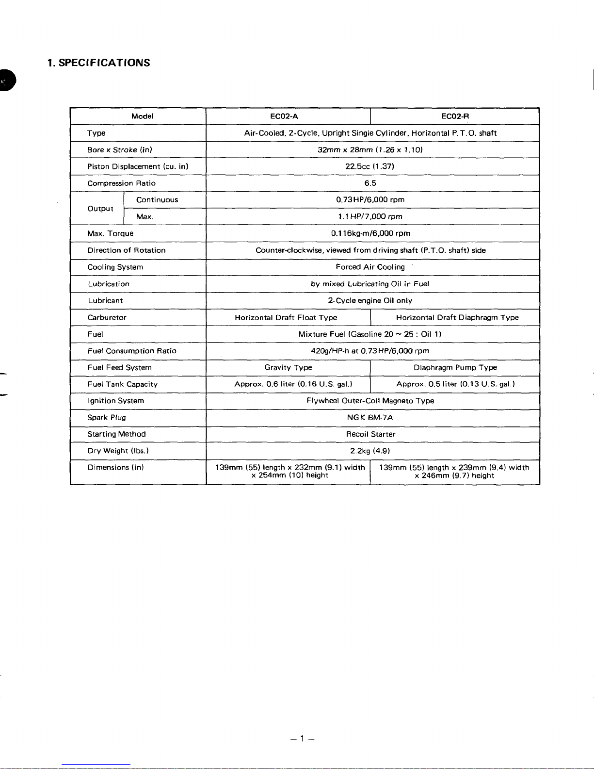
1.
SPEC1
FlCATlONS
-1-
Page 6
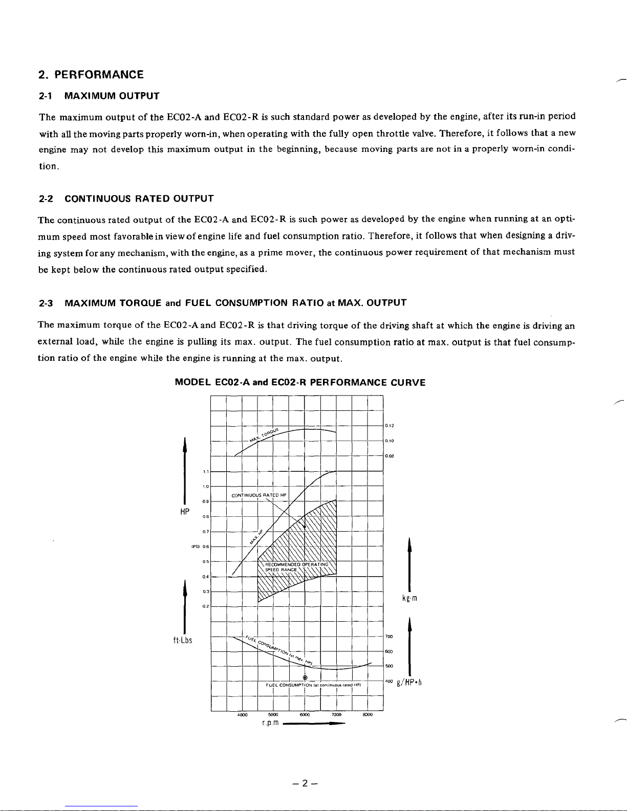
2.
PERFORMANCE
2-1
MAXIMUM OUTPUT
The maximum output of the EC02-A and ECOZ-R is such standard power as developed by the engine, after its run-in period
with all the moving parts properly worn-in, when operating with the fully open throttle valve. Therefore, it follows that a new
engine may not develop this maximum output in the beginning, because moving parts are not
in
a properly worn-in condi-
tion.
2-2 CONTINUOUS RATED OUTPUT
,"
The continuous rated output
mum speed most favorable in view
ing system
for
any mechanism, with the engine, as a prime mover, the continuous power requirement of that mechanism must
of
the EC02-A and EC02-R
of
engine
life
and fuel consumption ratio. Therefore,
be kept below the continuous rated output specified.
2-3
MAXIMUM
The maximum torque
external load, while the engine
tion ratio
of
TORQUE
and
FUEL CONSUMPTION RATIO at MAX. OUTPUT
of
the EC02-Aand EC02-R
is
pulling its rnax. output. The fuel consumption ratio at max. output
is
the engine while the engine is running at the max. output.
MODEL ECO2-A
HP
and
is
such power as developed by the engine when running at
that driving torque
ECOP-R PERFORMANCE CURVE
of
the driving shaft at which the engine is driving an
an
it
follows that when designing a driv-
is
that fuel consump-
opti-
ft-LbS
-2-
Page 7
3.
FEATURES
1.
COMPACT, LIGHT WEIGHT, HIGH PERFORMANCE and LOW FUEL CONSUMPTION
2.
TROUBLE FREE because of simple design and easy
to
handle
3.
HIGH DURABILITY engine withstand long severe operation
4.
TILTED OPERATION AVAILABLE
Be
able to operate at any position due to diaphragm carburetor.
5.
EASY STARTING with recoil starter
6.
Forged steel Crankshaft
7.
Ball main bearings at both ends
8.
Forged steel connecting
rod.
9.
With CHROME PLATED CYLINDER, HEAT CONDUCTIVITY and WEAR
PROOF
are quite excellent.
-3-
Page 8

4.
DISASSEMBLY
and
REASSEMBLY
4-1
PREPARATION
and
SUGGESTIONS
1) When disassembling the engine, memorize the locations
of
individual parts
so
as
to
be able to reassemble them correct-
ly. Tag parts if there
is
a possibility
of
confusion.
2)
Prepare several boxes
to
keep parts belonging to certain groups together.
3)
Group those parts related each other, tentatively assembling where they belong, immediately after removing, in order
to prevent missing and misplacing.
4) Handle the disassembled parts carefully and wash them in kerosene.
5)
Use the correct tools in the correct way.
6)
Standard tools required for disassembling and reassembling:
a) Work table
b) Washing pan
c) Disassembling tools
d) Washing oil (kerosene or gasoline),
2
cycle-oil
e) Emery paper, cloth
7)
Before starting
to
disassemble the engine, drain fuel.
8)
Tighten the screws of the cylinder, crankcase, connecting rod, spark plug, and flywheel
to
the specified torque values.
9) Use new packings and gaskets in reassembly.
10)
Immediately before assembling parts, wash them in fresh gasoline or kerosene and blow them dry.
1 1) Apply
2
cycle-oil on rotating and sliding
parts.
12)
Take care not
to
contaminate the parts by dust during assembling.
13)
Tighten bolts, nuts and screws with proper torque according
to
the
their sizes.
If
small screws are tightened too tight,
they may get broken.
14) After completely assembling the engine; turn it by hand and check if there
is
any abnormality or loose members.
,-
4-2
SPECIAL
TOOLS
(Fig.
1)
Fig.
1
-4-
Page 9

-
4-3
DISASSEMBLY
PROCEDURES
-
4-3-1 FUEL DRAIN
Drain fuel from the fuel tank,
4-3-2 THROTTLE
Wl
RE
(See
Fig.
2)
Remove throttle wire from carburetor together with piston
valve.
.-
Fig.
2
4-3-3 FUEL TANK
and
RUBBER
TUBE
L
1)
Disconnect fuel pipe between fuel tank and carbure-
I
tor at carburetor side.
2)
Remove fuel tank by unscrewing bolts.
3)
Only for
EC02-R
After removing fuel pump, push the head of rubber
tube toward arrow mark
in
Fig.
3
with a screwdriver
of
minus top (preferably not sharpened) and remove
rubber tube.
CA
U
TION:
NEVER REMOVE RUBBER
TUBE
EXCEPT AT RE-
P
LACEMENT.
BE SURE
TO
REPLACE
WITH
MEW ONE WHEN
RE-
MOVED.
BE
CAREFUL NOT TO DAMAGE THE HOLE
IN
WHICH
RUBBER TUBE WILL BE IMSERTED.
4-3-4 KILL SWITCH WIRE
Disconnect stop button wire terminal.
4-3-5 RECOl L STARTER
Remove starter case from crankcase by unscrewing bolts.
4-3-6 MAGNETO FLYWHEEL
(See
Fig.
4)
After removing nut, pull out flywheel from crankshaft,
Turn
cenler
bolt
clockwiw
FLYWHEEL'
~LYWHEEL
PULLER
.
.
*...
-
I.
Fig.
4
4-3-7
BREAKER,
C'ONDENSER,
and
COIL
(See
Fig.
5)
Remove breaker cover, condenser, breaker, and ignition coil
from crankcase by unscrewing bolts.
IGNITION
COIL
.*
Fig.
3
Fig.
5
Page 10

4-3-8 CARBURETOR and CARBURETOR BRACKET
(EC02-A), CARBURETOR and HEAT BLOCK
(EC02-R)
(See
Fig.
6)
Remove carburetor and carburetor bracket by unscrewing
bolts
(EC02-A),
and remove carburetor and heat block by
unscrewing bolts
(EC02-R).
HEAT
BLOCK
Fig.
6
4-3-9
MUFFLER
Remove muffler from cylinder by unscrewing bolts.
4-3-10 CYLINDER (See
Fig.
7)
Remove cylinder quietly
so
as not
to
damage sliding sur-
faces of cylinder and
piston.
CRP
Fig.
7
4-3-11
DIVISION
of
CRANKCASE
(See
Fig.
8)
After unscrewing bolts, disassemble front and rear crankcases from crankshaft by tapping with
a
soft
hammer.
Washing crankcase with gasoline, apply the film
of
oil
to
crankcase ball bearing bore and grease
to
oil
seal bore,
KCASE
FRONT
C~ANKCASE
I
CRANKSHAFT
Fig.
8
44
REASSEMBLY
PROCEDURES
4-4-
1
CRANKCASE
(See
Fig.
9)
1)
Insert crankshaft into front crankcase bearing.
2)
Assemble the crankcase.
3)
Use new gasket.
4)
Tighten bolts to
40-50
kg-cm
(2.9-36
ft-lbs) torque.
5)
Cut
off
crankcase gaskets stuck
out
to the mating sur-
face of cylinder.
CRANKSHAFT
Fig.
9
-6-
Page 11

4-4-2
CYLINDER
(See
Fig.
10)
1) Replace cylinder gasket with new one. At the same
time,
try
to mate the tapper hole with the groove
the contact surface
CAUTION:
TAKE CARE THAT GASKET
SITION
2)
3)
AND
ON
In assembling cylinder,
piston rings and cylinder.
Tighten bolts to 40-50 kg-cm (2.9-3.6 ft-lbs).
of
crankcase.
RIGHTSIDE.
take care
IS
PLACED
IN
RIGHTPO-
of
the position
4-4-6
IGNITION COIL
Tighten ignition
on
on
4-4-7 BREAKER
Insert knock pin
Tightening torque: 25 kg-cm
the right side.
coil
tentatively, putting high tension
of
breaker into the hole of crankcase.
(1.8
ft-lbs).
Regarding the adjustment of spark timing, refer to
of
Breaker Point adjustment Procedure.
4-4-8 CONDENSER
Assemble it, running stop wire through the bottom of condenser.
Tightening torque: 25
k2
kgcm
Tool: Plus driver, Torque wrench
wire
Section
5.
"A
Fig.
10
4-4-3 SPARK
PLUG
Tighten spark plug to 220-300 kgcm (1 5.9-21.7 ft-lbs).
4-4-4 CARBURETOR BRACKET
1)
Use
new
gasket.
OR
HEAT BLOCK
2) Tighten bolts to 50-70kg-cm (3.6- 5.1 ft-lbs) torque
for EC02-A and to 40-5Okgcm (2.9-3.6 ft-lbs) torque
for
ECO2-R.
4-4-5 CARBURETOR
(See
Fig.
11)
Tighten nuts to 50-7Okgcm (3.6-5.1 ft-lbs) torque for
ECO2-A and to 40-50kgcm (2.9-3.6 ft-lbs) torque for
EC02
-R
.
II
4-4-9 POINT
After inserting stop
COVER
wire
and primary wire into the groove
of crankcase, assemble point cover,
Tightening torque: 25 kgcm (1.8 ft-lbs).
4-4-10 FLYWHEEL
Mount flywheel on crankshaft and tighten flywheel nut.
Flywheel tightening torque
is
150-180 kgcm (10.8-13.0
ft-lbs).
4-4-1.1 IGNITION
COIL
(See
Fig.
12)
Tighten ignition coil, keeping' a clearance of 0.4-0.6 mm
from
flywheel.
Tightening torque: 25 kg-cm
(1.8
ft-Lbs).
/
,NIT1
-YWI
ON
HEEL
COIL
Fig,
1
1
-7-
Fig,
12
Page 12

4-4-1'2
MUFFLER
Tighten muffler to
90-
1
lOkgzm
(6.5-8.3
ft-lbs).
Use new gaskets.
4-4-13
TENTATIVELY TIGHTENING OF CYLINDER
COVER
Mount the both ends of cylinder covers on the mating portions of the crankcase and tentatively tighten with screws.
In Type A,
also
mount fuel tank stay together on the cylinder head with flat washers.
Tool: Plus Driver
4-4-14
RECOIL STARTER, STOP BUTTON
AND
GROMMET
Install stop button to starter case with toothed washer on
its
reverse side. Run high tension cord through the grommet
and assemble plug cap spring and plug cap. Run the grommet through the groove
of
starter case and tighten starter
case to crankcase with three screws.
Tightening torque: Stop button
25
+-2
kgcm
Starter case
45
+3 kg-cm
Tool: Plus driver, Torque wench
A-
.
,?
4-4-16
RUBBER TUBE
IN
FUEL TANK (EC02-R)
Insert the rubber tube in the hole of fuel tank from the end
of felt side
of
rubber tube. Use spacer or backing plate to
gently put in with vice or
squill
vice as shown in the figures.
Completely put in theridge of rubber tube. After inserting,
pinch the outer side
of
rubber tube and turn it to assure that
the ridge has been completely inserted.
Fig.
14
CA
U
TI0
N:
AFTER INSERTING,
BE
SURE TO CONFIRM THE
IN-
SERTION OF THE RIDGE
OF
RUBBER
TUBE.
4-4-15
TIGHTENING
OF
CYLINDER COVER
Tighten the cylinder cover.
Tightening torque:
45
*3
kg-cm
Tool: Plus driver, Torque wrench
Fig.
15
4-4-17
FUEL
TANK
Put spacer into fuel tank and install with screws. (Use a large
type flat washer.) Connect fuel line to carburetor.
Tightening torque:
45
*
3kg-cm
(3.3
*
0.2
ft-lbs)
Tightening torque:
45
k3
kg-cm
Tool: Plus driver, Torque wrench
-
8-
Page 13

5.
BREAKER POINT
1)
Remove starter case.
2)
Remove flywheel from crankshaft. (Flywheel nut is left-hand threads).
3)
Take off woodruff key from crankshaft and point cover.
4)
Remove carbon deposits on breaker point and clean mating surface by cloth or paper.
5)
Fit woodruff key to crankshaft,
6)
Tack flywheel, and set
again.
(See
Fig.
7)
Adjust as per the
a)
Loosen breaker fitting screw.
b) Confirm open/close condition of point by pushing breaker in the direction of arrow. Adjust breaker
to
be about
Notice that ignition timing will be over
8)
Point cover, magneto, starter case shall be assembled in order after point has been adjusted.
open. (Normal ignition timing will be
ADJUSTMENT
“F”
16)
Fig.
17
(under the condition stated
IGNITION
COIL
PROCEDURES
on flywheel to the mark on cfankcase. Then gently remove flywheel from crankshaft
in
item
6).
23O-27O)
30’
if point is opening under the condition shown in
\n
Fig.
so
that point may
17.
CRANKCASE
Fig.
16
Point
Point
cover
Fig.
Breaker-installing screw
17
-9-
Page 14

6.
CARBURETOR
ADJUSTMENT
Since the carburetor has carefully been adjusted at shop before shipment, avoid adjusting it unless absolutely necessary.
If
adjustment are needed, refer to the following.
1)
Idle adjustment
Adjust idling revolution with throttle stop screw,
(See
Fig.
?8)
EC02-A, EC02-R
If
turn throttle stop screw clockwise, revolution will increase. If turn
it counter-clockwise, revolution will reduce.
CUATION: DO NOT IDLE UNDER
2)
Fuel
flow
adjustment
a)
At low speed (at the small opening of the throttle)
is
When fuel
too
adjusting screw
b)
At high speed (at the large opening
When fuel
ing
screw
to
is
the
too
(See
RICH,
to
the
RICH,
LEFT.
CAUTION: LOW SPEED FUEL ADJUSTING SCREW
THAT THE DIRECTION
2,800r.p.m.
Fig.
18)
EC02-R
turn the low speed fuel adjusting screw to the
RIGHT.
of
the throttle)
turn high fuel adjusting screw
OF
TURNING SCREW
to
the
RIGHT.
IS
FOR ADJUSTMENT
IS
REVERSE
LEFT.
When it is too
When it is too
OF
TO
THAT OF HIGH SPEED FUEL ADJUST-
LEAN,
LEAN,
turn high speed fuel adjust-
AIR AMOUNT,
turn low speed fuel
SO
IT
IS
NOTED
ING SCREW.
r
THROTTLE STOP SCREW
LOW SPEED FUEL ADJUSTING SCREW
HIGH SPEED
Fig.
18
FUEL
ADJUSTING SCREW
i
/"
-
10
-
Page 15

PRESSI
7.
OPERATION OF FLOAT AND DIAPHRAGM CARBURETORS
DIAPHRAGM CARBURETOR FLOATCARBURETOR
JRE
CHANGE
IN
CRANKCA
PRIMER PUMP
LOW SPEED FUEL ADJUSTING SCREW
HIGH SPEED FUEL ADJUSTING SCREW
FROM
FUEL TANK
IDLE ADJUSTING SCREW
CARB VENTURI
TICKLER BUTTON
OVERFLOW
ATMOSPHERIC PRESSURE
7-1
OPERATION
VALVE
JET NEEDLE
OF
FLOAT
-
"".-
\
'
PRESSURE COMPENSATING DIAPHRAGM CHAMBER
CARBURETOR
fig.
STEEL BALL
19
1) Fuel from the fuel tank enters the float chamber through the needle valve, which is kept open while the fuel level is
low.
2)
When the fuel level rises, the float is allowed to move up and lift the arm connected to the needle valve.
3)
The arm lifted
4)
When the fuel
by
the main je't and the jet needle the fuel level falls low, causing the float to move down.
5)
The falling of the float lowers the arm connected to the needle valve, which admits the fuel to enter the float chamber.
After this, the same operations in 1)
by
the float raises the needle valve, which shuts off the supply of fuel.
in
the float chamber
is
suctioned into the engine through the carb venturi, the fuel amount
-
5)
are repeated.
is
measured
-
11
-
Page 16

7-2 OPERATION OF DIAPHRAGM CARBURETOR
1)
When the engine runs, positive pressure and negative pressure will alternately occur in the crankcase. This alternation
in pressure
2)
The fuel drawn up by fuel pump enters pressure compensating diaphragm chamber through the felt, rubber tube in fuel
tank, fuel pipe and needle valve.
3)
The fuel
than atmospheric pressure and pushes down the pressure compensating diaphragm.
4)
When the pressure Compensating diaphragm is pushed downwards, the arm connected to needle valve turns clockwise
by
the strength
5)
The fuel in pressure compensating diaphragm chamber
entering the engine through the carb venturi. Then, the pressure in pressure compensating diaphragm chamber becomes
lower than atmospheric pressure and the diaphragm is pushed up against the strength
6)
When the pressure compensating diaphragm
needle valve, which admits fuel to enter. After this, the same operations in
NOTE:
I.
OPERATION
When the opening of the throttle
and jet needle. Therefore, even by low speed fuel adjusting screw, fuel
density of fuel. Accordingly, in high and low speed fuel adjusting screws, the direction of turning the screw
each other. For instance, when the opening of the throttle
ing screw TO THE RIGHT to make the fuel lean, but when the opening of the throttle
turn low speed fuel adjusting screw TO THE LEFT to make the fuel lean.
2.
OPERATlON
1)
When tickler button
lowering needle valve, which allows fuel to enter.
At the same time, when the tickler button
2)
In
pensating diaphragm chamber
chamber
3)
Further, when primer pump
overflow valve and, at the same time, a
justing screw and jet needle.
4)
A little amount of fuel sent to carb venturi by the operation of
engine, and becomes somewhat rich and suitable fuel for easy starting of the engine.
is
led to the reverse side of fuel pump diaphragm
in
pressure compensating diaphragm chamber
of
spring and pushes
OF
LOW
OF
TICKLER BUTTON
a condition of
is
filled with fuel.
SPEED
1/,
if
FUEL
is
small,
is
pushed up, the lever connected to needle valve turns left against the strength of spring,
primer pump
is
exhausted throught the overflow valve,
is
operated continuously, fuel
so
that the top side will work as fuel pump.
is
sent by pressure,
up
the needle valve, which shuts out the supply of fuel.
is
measured by high speed fuel adjusting screw and jet needle,
is
pushed up, the arm turns counterclockwise against the spring and lowers
ADJUSTING
it
is
not sufficient to measure the fuel only by high speed fuel adjusting screw
is
repeatedly pushed, fuel
little
SCREW
is
LARGE and the fuel
is
pushes up, overflow valve
is
pumped up from
is
forced to flow into the overflow pipe through the
amount of fuel
is
sent to carb venturi through the high speed fuel ad-
31,
so
that the fuel pressure becomes higher
1)
-
6)
are repeated.
is
measured and sent to the venturi to adjust the
is
is
also held open through the lever.
so
that the pressure compensating diaphragm
if recoil starter
of
spring.
RICH,
turn high speed fuel adjust-
is
SMALL and the fuel
the
tank and air in pressure com-
is
pulled,
it
is
taken into the
is
reverse to
is
RICH,
f-
/"
-
12
-
Page 17

8.
TROUBLE
SHOOTING
For a gasoline engine to start and run satisfactorily, the following three requirements must be met:
1) The cylinder filled with a proper fuel-air mixture.
2)
An appropriate compression in the cylinder.
3)
Good spark at correct time
to
ignite the mixture.
If all the three requirements are not met simultaneously, an engine can not be started. There are also other factors
heavy load at starting and
most
common causes
8-1
STARTING
DIFFICULTIES
too
long an exhaust pipe causing a high back pressure, which contribute to hard starting. The
of
engine troubles are given below.
such
as
Cause
Defects
in
spark
plug
Defects in contact
cable
Defects in contact
breaker
Defects in magneto
Other defects in
electric system
Remedy
1)
If
contaminated, wash in gasoline, remove
foreign material and dry.
2)
If spark plug
replace plug.
3) Adjust spark gap to 0.6-0.7mm
is
broken and lost insulation,
(.024-
,027").
If cable is burnt, replace cable along with coil.
1)
If breaker points are rough, smooth out
surface with emery paper
2)
If breaker point gap
specified 0.35t0.05mm by loosening contact support plate lock screws.
3)
If
spark timing is incorrect, adjust
23"
-
27'
before TDC.
4)
If breaker is defective in insulation, replace
breaker.
5)
If
condenser
1)
If wire or insulation
magneto.
2)
If
magnetism
magneto maker)
1)
If kill switch
replace or repair.
2)
If primary wire
body, insulate
tape.
is
defective, replace.
is
weak, re-magnetize (at the
or
is
is
it
(#400).
is
incorrect,
is
replace.
faulty, (short circuiting)
grounded
with insulating adhesive
adjust
it
it
broken, replace
to
the engine
to
to
Preventive measure
1)
Use spark plugs
not
use
poor grade oil. Clean air cleaner and
avoid dust entry.
2)
When spark gap is adjusted, if center elec-
is
trode
damaged.
of
specified heat range. Do
hit or bent, insulator may
get
1)
Gas leak from
combustion chamber
Defects in piston
assembly
Defects in fuel tank
system
If spark plugs are
2)
If
1)
If
2)
If
31
If piston rings are stuck, clean or replace
rings.
1)
Clean clogged tank outlet.
2)
Clean clogged fuel strainer.
3)
If incorrect fuel
water is mixed, drain tank completely and
fill
4)
When fuel pipe is locked with
5)
If
rubber components of fuel line system,
due
loose,
tighten.
spark plugs are defective, replace.
piston
is
worn, replace.
piston rings are worn, replace.
is
poured into tank or
it
with correct fuel.
there
is
any crack or damage in the
to
their deteroriation, replace.
air,
-
13
-
expel1 air.
1 ) Keep air cleaner always clean.
2)
Do
not use poor grade oil. Change oil
regularly.
1)
Be sure
to
2)
Use mixture (gasoline
use a filter when adding fuel.
20 - 25
:
oil
1
I
as fuel
Page 18

/"
8-2
OVERHEATING
CaUSe
Defects in carburetor
Defects in carburetor
Piston or Connecting
Rod
seized
Remedy
1)
If
clogged
2)
If
defective. replace.
Clean
with
dust, clean.
jets
and other orifices.
if
they are
clogged.
1)
Start engine with fully open choke valve and
fully open throttle valve.
2)
Remove spark plug and disconnect fuel pipe,
repeat starting operation several times to evacuate excess fuel.
If
fuel overflows, check needle valve seat for
wear. Replace. if necessary.
1)
If piston seizes, correct or replace.
2)
If connecting rod large end or small end
seize, replace.
Preventive measure
1)
Never close choke valve when engine
warm.
2)
When stopping the engine,
speed
Tor a while. This practice not only
favourably affects next starting,
improves engine life.
3)
Clogged aircleaner results
fuel mixture.
Clean
it
thoroughly.
Be careful clogged carburetor.
1)
Do
not use poor grade oil.
2)
Use
fuel of proper mixing ratio.
run
in
~ ~~ ~~ ~
it
at
but
too rich air-
is
slow
also
1)
If the ignition timing is
2)
If
too much carbon deposits
3)
If the heat range of the spark plug
4)
If the air-fuel mixture is too lean, clean jets and other holes
5)
If the load is in excess, reduce it below the specified continuous load.
POWER
If
DROP
the cylinder, piston or piston rings are worn, replace them.
too
far advanced, correct to
in
the combustion chamber, remove it.
is
too cool, replace it with correct one
23' - 27'
If the carburetor is out of order, re-adjust or clean it.
If
the
spark
plug
is
faulty (contamination, gas leakage
If
the magneto or the contact breaker
If
the aircleaner
is
clogged, clean it.
is
faulty, replace them
or
If the fuel system is clogged, clean it.
If
the
oil
seals at the crankshaft are
8-4
EXCESSIVE FUEL
1)
If too rich air-fuel mixture, clean jets and small holes
2)
If
fuel leakage, re-tighten screws or replace.
3)
If
beside these causes,
CONSUMPTION
also
worn
and let the compressed gas through, replace them.
in
caused by power drop, perform remedies for power drop, according to
DROP.
(NGK
BM7A).
in
the carburetor. Clean the aircleaner also.
faulty insulation), clean it or replace it.
or
re-adjust them.
carburetor.
7-3.
POWER
-
-
14
-
Page 19

-
8-5
ENGINE HUNTING
-
If the fuel-air mixture is too lean. Clean the carburetor.
8-6
OTHER
1) Fuel overflow from carburetor
If the fuel flows towards the aircleaner or much fuel flows into the crankcase while the engine
flowing), the needle valve or the float is faulty. Correct
2)
If the engine suddenly stops with abnormal noise, the piston or the crankshaft and connecting rod assembly is seized.
Correct them or replace them.
3)
If the engine produces abnormal noise during operation, be sure to stop the engine and do not start it again before the
cause
If the cause for the trouble is not found, contact our distributor and entrust the engine in the hand
engineer.
COMPLAINTS
is
found.
or
replace them.
is
standing still (over-
of
our service
-
15
-
Page 20

9.
CHECKS
After disassembling and cleaning the engine parts, check them, and if necessary, correct them according to the correction
table. The correction table applies whenever engine are repaired. Its contents should be thoroughly understood by those
who undertake the repairing. Its specifications must be abided by to effect correct maintenance.
Below, terms employed in the correcrion table as explained.
1)
CORRECTION
All operations performed on the engine parts for the purpose
consisting
2)
STANDARD
The design dimensions of the part without the tolerance.
3)
CORRECTION TOLERANCE
The tolerance on the re-finished part dimension or
4)
CORRECTION LIMIT
The limit on the part and adjustment, beyond which any dimensional and functional changes, due
other causes will adversely affect the normal engine performance.
5)
USE
The limit, beyond which the part is no longer usable, due to defects in function or strength.
NOT€:
and
CORRECTIONS
of
repairs, readjustments, and replacements.
SIZE
LIMIT
ALL
DlMENSlONS IN
THE
'%ORRECTION
of
improving or recovering the engine performance,
on
the readjusted dimension.
to
wear, burn, and
TABL€"are given in millimeter, except where otherwise specified.
/"
ITEM
Breaker, condenser point cover, & ignition coil
0.
Carburetor
g
c-
.-
Tank, starter
E
c
r
2
Heat
I-
2
.-
'c
0
Flywheel
g
v)
Spark plug
case
Block
kg-crn
23 - 27
42
-
42 - 48 Crankcase
42
-
42
-
42 - 48 Cylinder & muffler
150
-
220
-
48
48
48
180
300
ft-lbS
1.7
-
1.9
3.0
-
3.5
3.0
-
3.5
3.0
-
3.5
3.0
-
3.5
3.0
-
3.5
10.8 - 12
15.9
-
21.7
TOOL
Torque
Wrench
,"--
-
16-
Page 21

CORRECTION
TABLE
iTEM
Clearance between
cylinder
Cylinder bore
Piston
Side clearance
piston ring
Width of ring
groove
Ring width
Ring gap
Clearance between
piston
Piston pin hole
Piston
Side clearance
connecting rod
large end
Run-out
shaft
Axial clearance
crankshaft iournal
Tightness of main
bearing
Housing inner dia.
Clearance of main
bearing
Bearing inner dia.
Crankshaft
dia.
Connecting rod
small end
Ignition timing
&
O.D.
&
piston
pin
of
outer
O.D.
I.D.
piston
of
pin
O.D.
of
crank-
of
dia.
O.D.
I.D.
STANDARD
SIZE
0.020L
-
0.057L
I
32.01 dia
31.99 dia.
1
o,ol
-
o,08L
1.6
I
1.6
0.1
-
0.3
I
0.007T
-
0.008L
8
dia.
8
dia.
0.1
L-0.5L
1
0.05
I I
0.05 - 0.6
0.014T - 0.036T
28
dia.
28
dia.
I
0.008T
-
0.008L
12 dia.
12 dia.
11
I
dia.
25'
before top
dead center
CORRECTION
LIMIT
0.12L
1
32.01 dia.
31.99 dia.
I
I
I
I
I
I
I
I
0.13L
1.6
+0.08
1.64.05
0.6
0.03L
8
dia
+0.02
8
dia. -0.01
0.7L
0.1
0.8
0
28 dia.
28
dia. -0.01 Bearing
0.014L
12 dia.
12
dia. -0.01
11 dia
+0.04
-0.05
-0.01
+0.003
+0.02
R
EMAR
KS
I
at middle portion
at middle portion
Max. width
groove
1
"in.
Max. inner dia.
Min.
Supporting assembled
crankshaft between
centers, measure
journal where
1
from
of
ring width
outer dia.
crankcase
ring
is
5mm
I
I
I
I
I
TOOL
Cylinder gauge
Micrometer
Feeler gauge Replace
Block gauge
Micrometer
Feeler gauge
Micrometer
Feeler gauge
Dial gauge
Dial gauge
Cylinder gauge
Micrometer
I
Cylinder gauge
1
CORRECTION
METHOD
Replace
1
Replace
Replace
Replace
I
Replace
Replace
Replace
Replace Cylinder gauge
Replace
Replace
Correct
I
Replace
Replace
Replace
I
Replace
rReplace
Replace
Replace Dial gauge
1
I
Timing tester
Adjust
Point gap
Air gap
Spark plug gap
1
0.35
0.2
0.6-0.7
I
-0.05
+0.05
+o.
0
kO.1
Feeler gauge
1
-
17
-
Feeler gauge
Thickness gauge
1
Adjust
Adjust
Adjust Feeler gauge
Page 22

10.
MAINTENANCE
and
STORING
The following maintenance jobs apply when the engine is operated correctly under normal conditions. The indicated maintenance intervals are by
engine is operated in extremely dusty conditions, the air cleaner should be cleaned every
10-1
DAILY CHECKS
1)
Remove dust from whatever which accumulated dust.
2)
Check external fuel leakage. If any, retighten or replace.
3)
Check screw tightening. If any loose one is found, retighten.
10-2
EVERY
1)
Check spark plug. If contaminated, wash in gasoline or polish with emery paper.
2)
Clean air cleaner.
10-3
EVERY
1)
Clean fuel strainer and fuel tank.
2)
Clean contact breaker points.
3)
Clean exhaust port
50
HOURS CHECKS
150
no
means guarantees for maintenance free operations during these intervals. For example,
and
MAINTENANCE
HOURS CHECKS
of
cylinder and both inlet and outlet
and
MAINTENANCE
and
MAINTENANCE
of
muffler.
day,
instead
of
every
50
if
hours.
/"
the
10-4
YEARLY CHECKS
1)
Remove carbon from cylinder head and piston head.
2)
Clean fuel tank inside.
3)
Clean carburetor diaphragm chamber inside. (In type
4)
Clean contact breaker and adjust point gap.
5)
Replace fuel line once a year.
10-5
PREPARATION
1)
Perform the above
2)
Drain fuel from the fuel tank and carburetor float chamber. (In case type R with diaphragm carburetor, run the engine
until
it
stops from lack
3)
Remove spark plug, and apply
times
by
pulling the recoil starter handle slowly. Re-install the spark plug.
4)
Clean the engine outside with oiled cloth.
5)
Put a vinyl or other cover over the engine and store the engine in dry place.
and
MAINTENANCE
for
LONG ABEYANCE
9-1
and
9-2
maintenance jobs.
of
fuel.)
5
to lOcc
A,
float chamber inside)
of
lubricating oil through the spark plug hole. Perform idle operation several
-
18
-
Page 23

Industrial
Engines
 Loading...