

Page 1
SERVICE
MAIINJAL
Model
EC12
OIL MIX & OIL INJECTION ENGINES
puB-Esl173
Rev. 8/98
Page 2
CONTENTS
Section
Title
Page
1
.
2
.
3
.
4
.
5
.
6
.
7
.
8
.
9
.
4-1
4-2
4-3
4-4
4-5
4-6
4-7
4-8
4-9
4-1
0
4-1
1
Page 3
Page 4
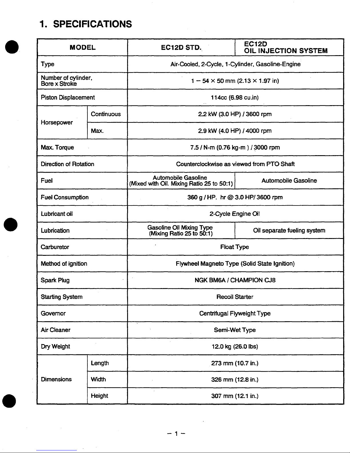
MODEL
ECIPD
STD.,
EC12D
1
OIL
INJECTION SYSTEM
Type
of
Number
Bore
Piston Displacement
Horsepower
Max.
Direction
Fuel
Fuel
Lubricant
Lubrication
cylinder,
x
Stroke
Toque
of
Rotation
Consumption
oil
Continuous
(Mixed
Air-Cooled, 2-Cycle, 1 -Cylinder, Gasoline-Engine
1
7.5
Counterclockwise
Automobile Gasoline
with
Oil.
Mixing
Ratio
360
Gasoline
(Mixing
Oil
Mixing Type
Ratio
25
to
-
54
x
50
1
14cc
.
-.
22
kW
(3.0
2.9 kW
I
g
50:l)
(4.0
N-rn
(0.76
25
to
50:l)
/
HP.
hr
2-Cycle Engine
mrn
(2.13 x 1.97
(6.98
HP)
HP)
kg-m
as
viewed
I
I
0
3.0
I
cu.in)
/
3600
I4000
)
I3000
from
HP/
3600
Oil
O~I
in)
rpm
rpm
rprn
PTO
Shaft
Automobile Gasoline
rprn
separate fueling system
Carburetor
Method
spark
Starting System
Governor
Air
Dry Weight
Dimensions Width
of
Plug
Cleaner
ignition
Length
Height
Float Type
Flywheel Magneto
NGK
BMGA I CHAMPION
~ ~ ~
Recoil Starter
12.0
273
326
307
Type
kg
mrn
rnrn
rnm
(Solid State Ignition)
CJ8
(26.0
Ibs)
(10.7
in.)
(12.8
in.)
(12.1
in.)
-1-
Page 5
2.
2-1
MAXIMUM
OUTPUT
The maximum output
is
the output
of
an engine with its throttle valve fully opened under the condition
that all the moving parts are properly
worn
in after the initial break-in period.
A
new engine may not produce full maximum output while its moving parts are still
not
broken-in.
2-2
CONTINUOUS
RATED
OUTPUT
The
continuous rated output
is
the output
of
an
engine at optimum
governed
speed which is most
favorable from the view point
of
engine’s life and fuel consumption.
When the engine
is
installed on a certain equipment, it
is
recommended. that the continuous output
required from the
engine
be
kept below this continuous rated output.
2-3
MAXIMUM
OUTPUT
The maximum torque is the torque at the output shaft
when
the engine
is
producing
maximum output at
certain revolution.
-2-
Page 6
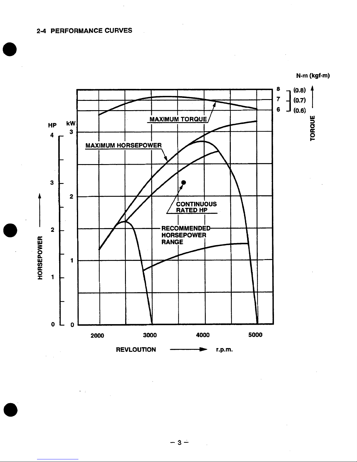
2-4
PERFORMANCE
CURVES
Nm
(kgf-m)
HP
4
3
0
kW
3
2
1
-0
2000
3000
4000
5000
REVLOUTION
-
r.p.m.
Page 7
3.
FEATURES
3-1
COMPACT,
LIGHT
WEIGHT
AND
HIGH
POWER
Compact and light weight engine thanks to
3-2
SUPERB
Rugged design on each engine components and employment
a long lasting durability even
3-3
SfMPLE
Maintenance free and
governor system.
Easy
34
SUITABLE
Robin
your equipment,
3-5
OIL
Oil
and gasoline are placed into separate tanks. Therefore, mixing the fuel/oil which
troublesome, is
Because the fuel
Since
The mixture ratio has become leaner, which will decrease white smoke during operation.
DURABILITY
STRUCTURE,
start
with decompression
FOR
EC12
INJECTION
only
engine has the identical mounting flange
gasoline
in
harsh applications.
EASY
high
REPLACEMENT ENGINE
EC12
SYSTEM
now
is
engine
done automatically
gasoline, the
is
in the carburetor, there
MAINTENANCE
vibration proof
hole
on
can
replace
(OIL
INJECTION
start
short
connecting rod and aluminum cylinder.
have
exhaust system.
EClO
by
ability
engines.
TYPE)
engine function.
of
the
engine for the reason
will
be
of
high
anti-vibration dust cover enable
been achieved
as
EClO
no
jet choking due to the deterioration
thanks
engines. Without
to the crankcase built in
can
be improved.
any
modification on
often
can
of
be
oil.
4.
GENERAL
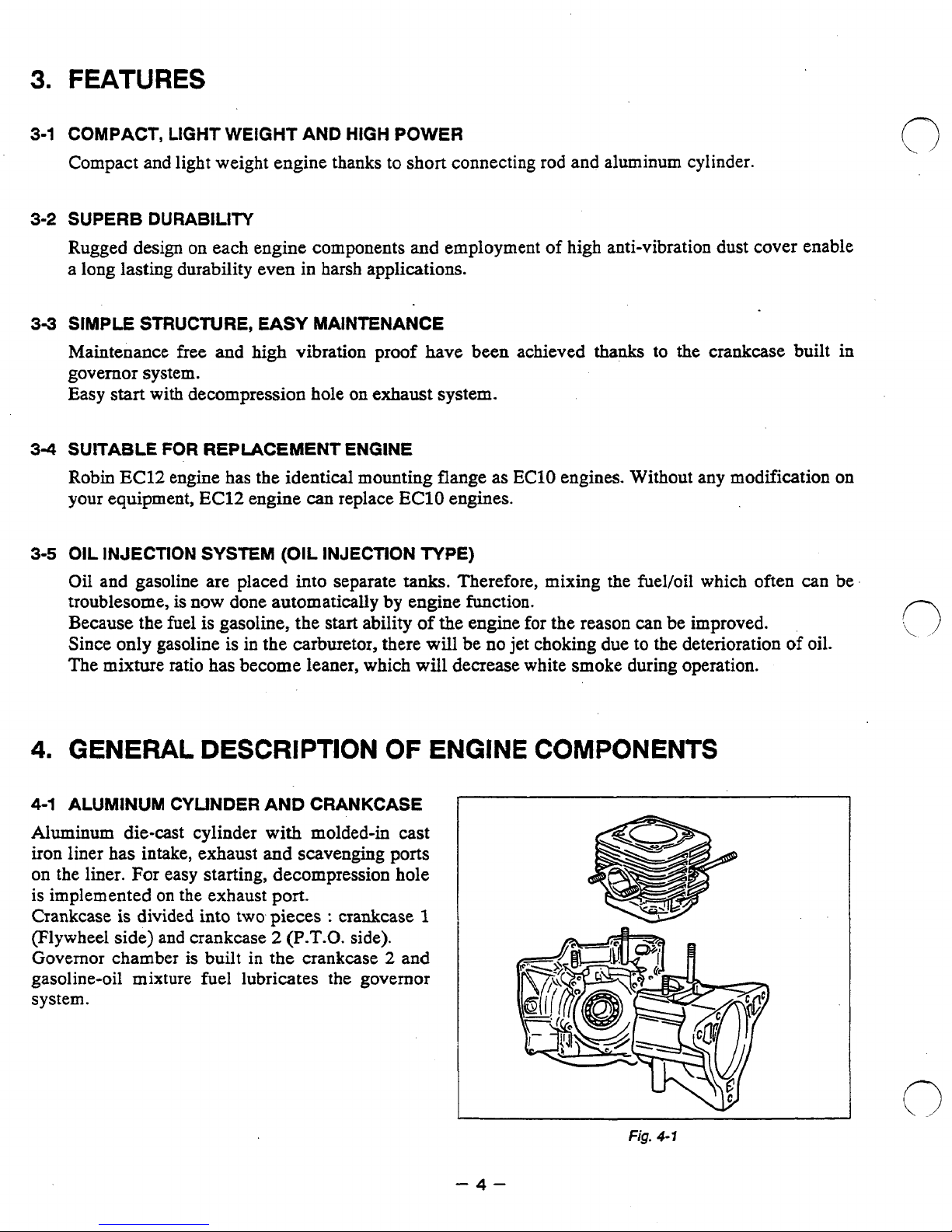
4-1
ALUMINUM CYLINDER AND CRANKCASE
Aluminum die-cast cylinder with molded-in cast
iron liner has intake, exhaust
on the liner. For easy starting, decompression hole
is implemented on the exhaust port.
Crankcase is divided into two pieces
(Flywheel
Governor chamber
gasoline-oil mixture fuel lubricates the governor
system.
side) and crankcase
DESCRIPTION
and
scavenging
:
2
(P.T.O.
is
built in
the
crankcase
OF
ports
crankcase
side).
2
and
1
ENGINE
-4-
COMPONENTS
Fig.
4-7
Page 8
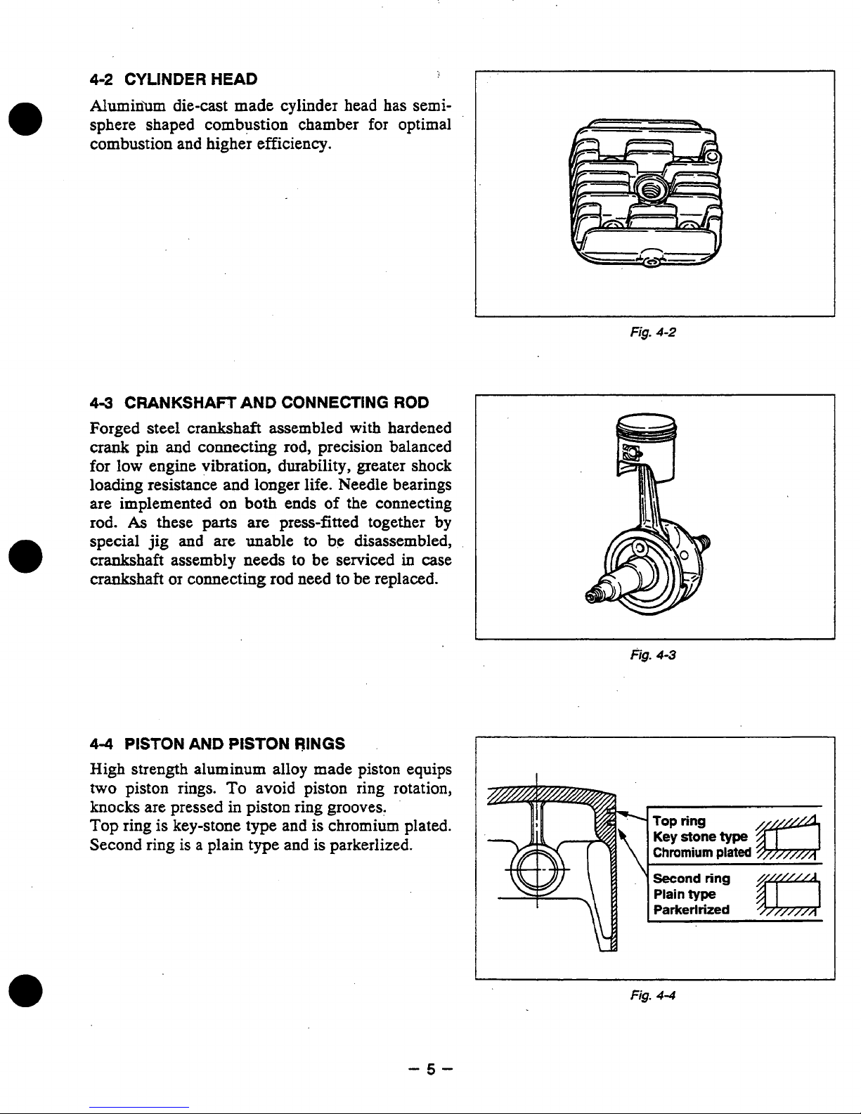
4-2
CYLINDER
HEAD
Alumin’um die-cast made cylinder head has semi-
for
sphere shaped combustion chamber
optimal
combustion and higher efficiency.
49
CRANKSHAFT
AND CONNECTING
ROD
Forged steel crankshaft assembled with hardened
crank
pin
and
connecting rod, precision balanced
for low engine vibration, durability, greater shock
loading resistance
are implemented
rod.
As
these
special
jig
and
crankshaft assembly
crankshaft
or
and
longer life. Needle bearings
on
both
ends
of
the connecting
parts
are
press-fitted together
are
unable to be disassembled,
needs
to
be serviced
in
case
connecting rod need to be replaced.
by
1
Fig.
4-2
4-4
PISTON
High strength aluminum alloy made
two
piston rings.
knocks are pressed
Top
ring is key-stone type and is chromium plated.
Second ring is a plain type and
AND
PISTON
RINGS
piston
To
avoid piston ring rotation,
in
piston ring grooves.
is
parkerlized.
equips
fig.
4-3
Top
Key stone
Chromium
Plain
Parkerlrized
ring
type
plated
type
-5-
Page 9
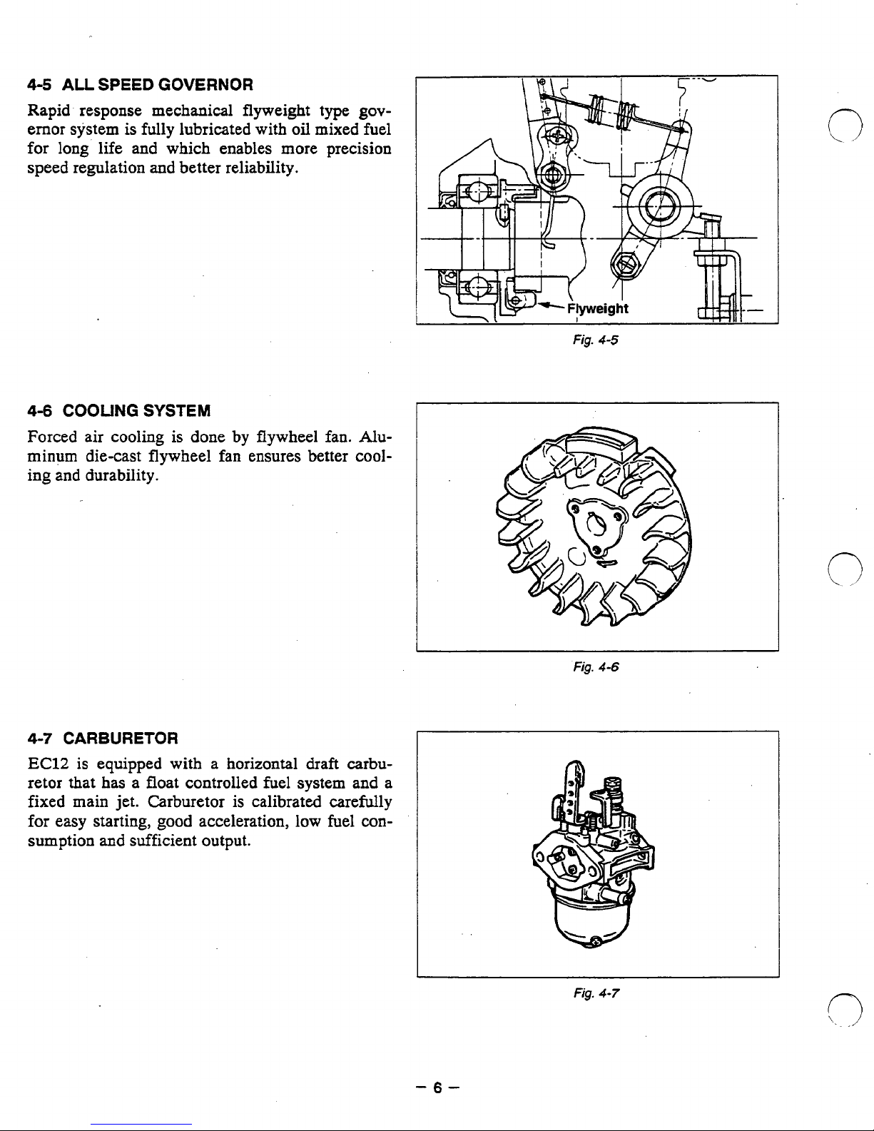
4-5
ALL
SPEED
GOVERNOR
Rapid response mechanical flyweight type
ernor system
for
long'
speed regulation
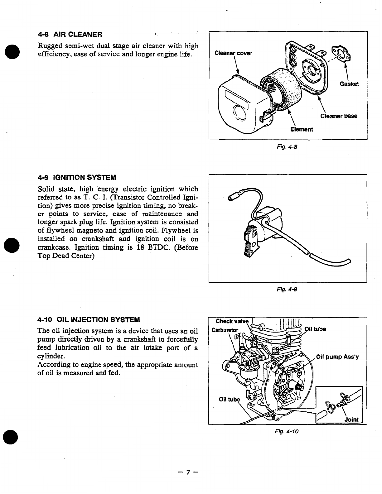
4-6
COOLING
Forced air
is
fully lubricated with oil mixed fuel
life and which enables more precision
and
better reliability.
SYSTEM
cooling
is done by flywheel
fan.
gov-
Alu-
minum die-cast flywheel fan ensures better cooling and durability.
I
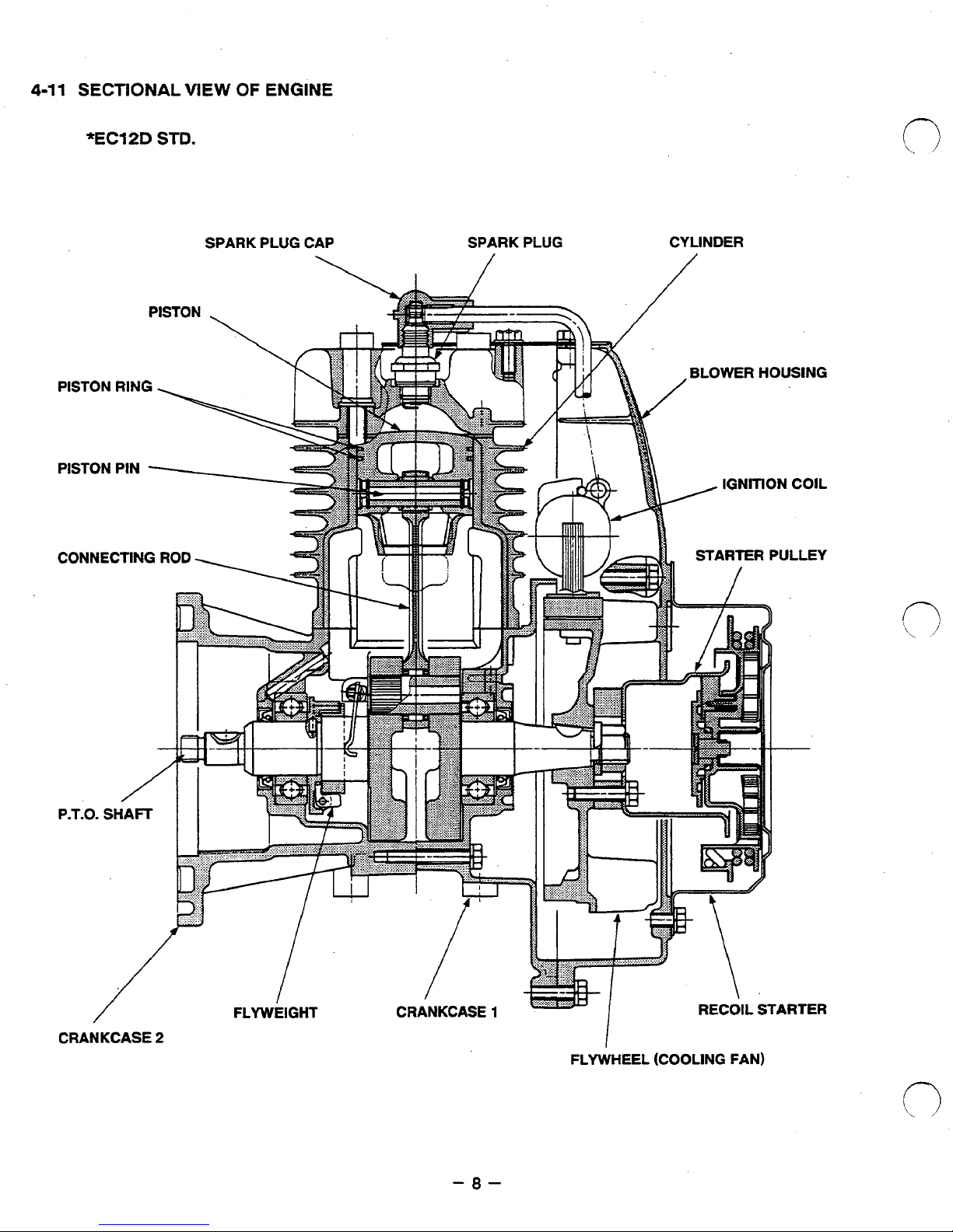
4-7
CARBURETOR
EC12
retor that
is
equipped with a horizontal draft carbu-
has
a float controlled
fuel
system and a
fixed main jet. Carburetor is calibrated carefully
good
for easy starting,
sumption
and
sufficient output.
acceleration, low fuel
con-
Fig.
Fig.
4-6
4-7
-6-
Page 10
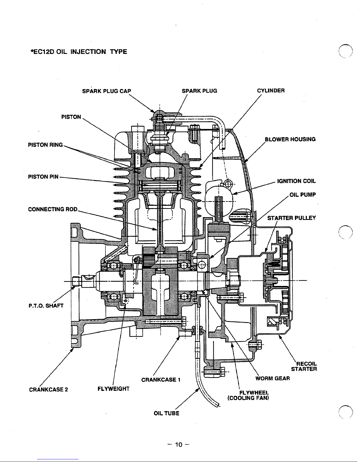
4-8
AIR
CLEANER
Rugged semi-wet dual stage air cleaner with high
0
efficiency, ease
of
service
and
longer engine life.
4-9
IGNITION
SYSTEM
Solid state, high 'energy electric ignition
which
referred to
as
T.
C.
I.
(Transistor Controlled Igni-
tion) gives more precise ignition timing,
no
break-
er points
to
service, ease
of
maintenance and
longer spark.plug life. Ignition system
is
consisted
of
flywheel
magneto and
ignition
coil.
Flywheel
is
installed
on
crankshaft
and
ignition coil is
on
crankcase.
Ignition timing
is
18
BTDC.
(Before
Top Dead Center)
4-10
OIL
INJECTION
SYSTEM
The
oil
injection system
is
a device that uses
an
oil
pump
directly
driven
by
a
crankshaft
to forcefully
feed
lubrication
oil
to
the
air intake
port
of
a
cylinder.
According to engine speed, the appropriate amount
of
oil is measured and fed.
Element
\
Fig.
4-8
I
Fig.
4-9
Fig.
4-10
-7-
Page 11
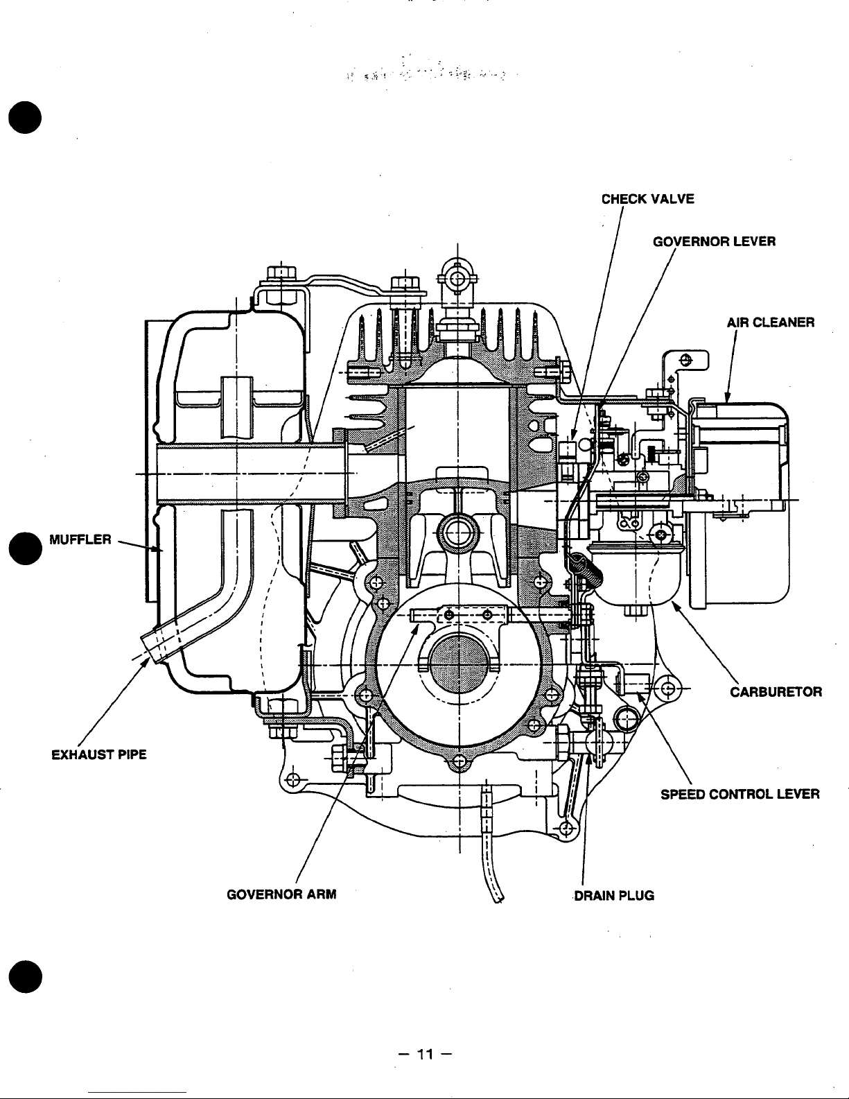
4-11
SECTIONAL
VIEW
OF
ENGINE
*EC12D
STD.
SPARK PLUG CAP
SPARK
PLUG
CYLINDER
CRANKCASE
2
-8-
I
FLYWHEEL
(COOLING FAN)
Page 12

GOVERNOR
I
/
LEVER
/
EXHAUST
-9-
Page 13
*EC12D
OIL
INJECTION
TYPE
SPARK
PLUG CAP SPARK PLUG
CYLINDER
OIL
TUBE
-
10-
Page 14
MUFFLER
/
EXHAUST
-
17
-
Page 15
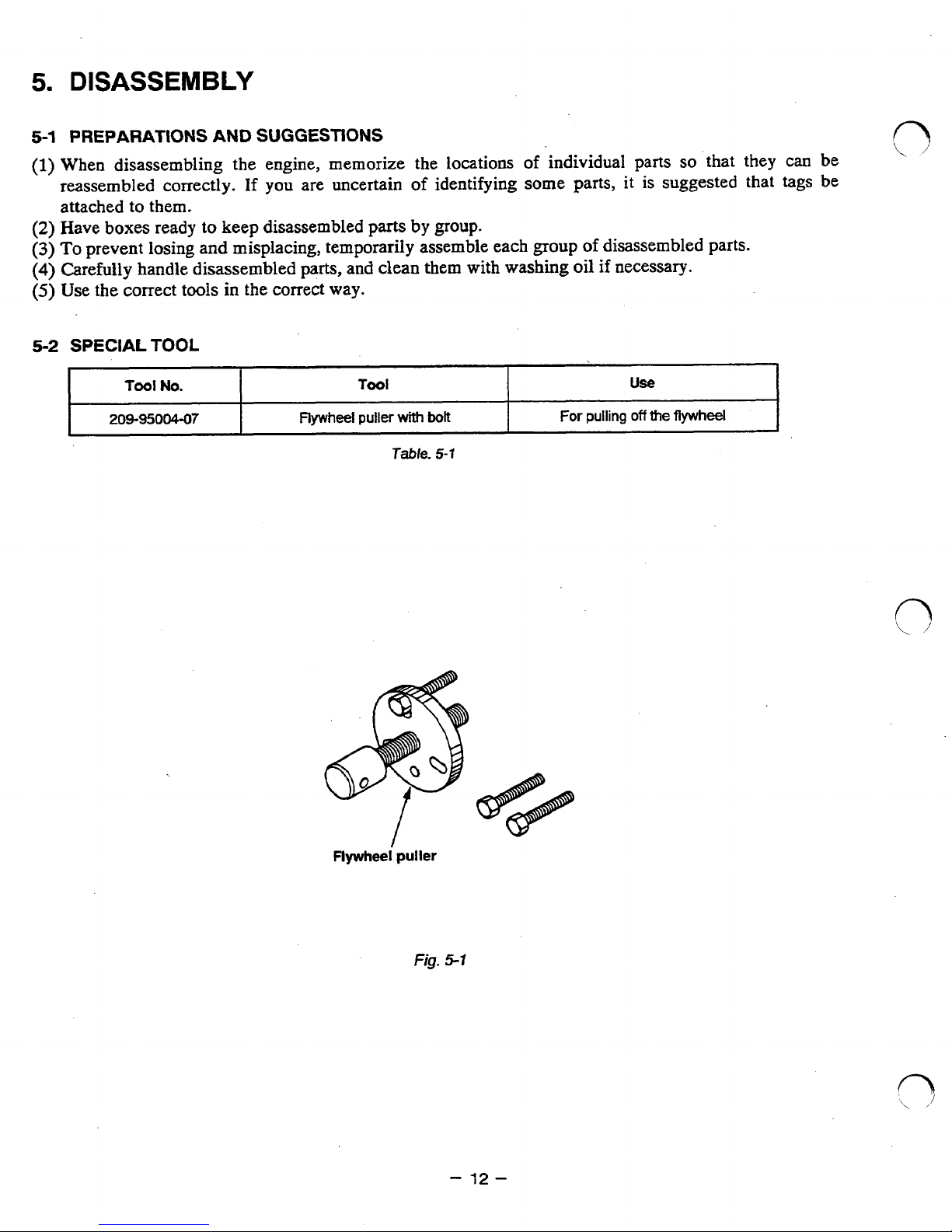
5.
DISASSEMBLY
5-1
PREPARATIONS
AND
SUGGESTIONS
(1)
When disassembling the engine, memorize the locations
of
individual parts
so
that
they
can be
reassembled correctly.
If
you are uncertain
of
identifying some parts,
it
is suggested that tags be
attached to them.
(2)
Have boxes ready
to
keep disassembled
parts
by
group.
(3)
To
prevent losing and misplacing, temporarily assemble each
group
of
disassembled parts.
(4)
Carefully handle disassembled
parts,
and
clean
them
with
washing
oil
if
necessary.
(5)
Use
the
correct tools in the correct
way.
5-2
SPECIAL
TOOL
Tool
No.
US€!
Tool
209-95004-07
For
pulling
off
the
flywheel
Flywheel puller
with
bolt
Table.
5-1
Flywheei puller
fig.
5.1
-
12-
Page 16
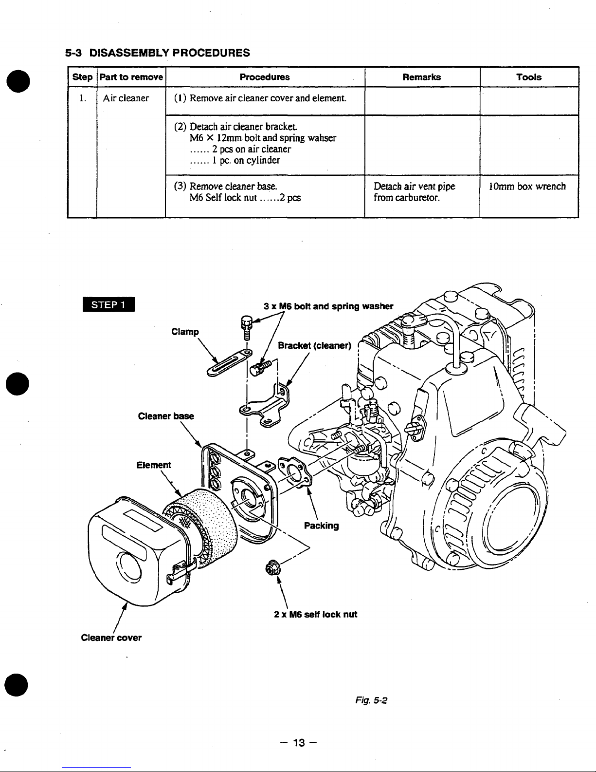
53
DISASSEMBLY
Part
Step
1
1.
1
Air
I
to
remove
cleaner
PROCEDURES
1
(1)
Remove
(2)
Detach
M6
......
......
I
(3)
Remove cleaner base.
M6
air
air
cleaner bracket
X
12mm
2
pcs
on
1
pc.
on cylinder
Self
lock
Procedures
cleaner
bolt
air
nut
cover
and
cleaner
.....
and element.
spring
-2
pcs
wahser
1
Detach
from
Remarks
air
vent
carburetor.
pipe
I
lOmm
Tools
box
wrench
I
I
Cleaner cover
1
-
13-
Fig.
5-2
Page 17
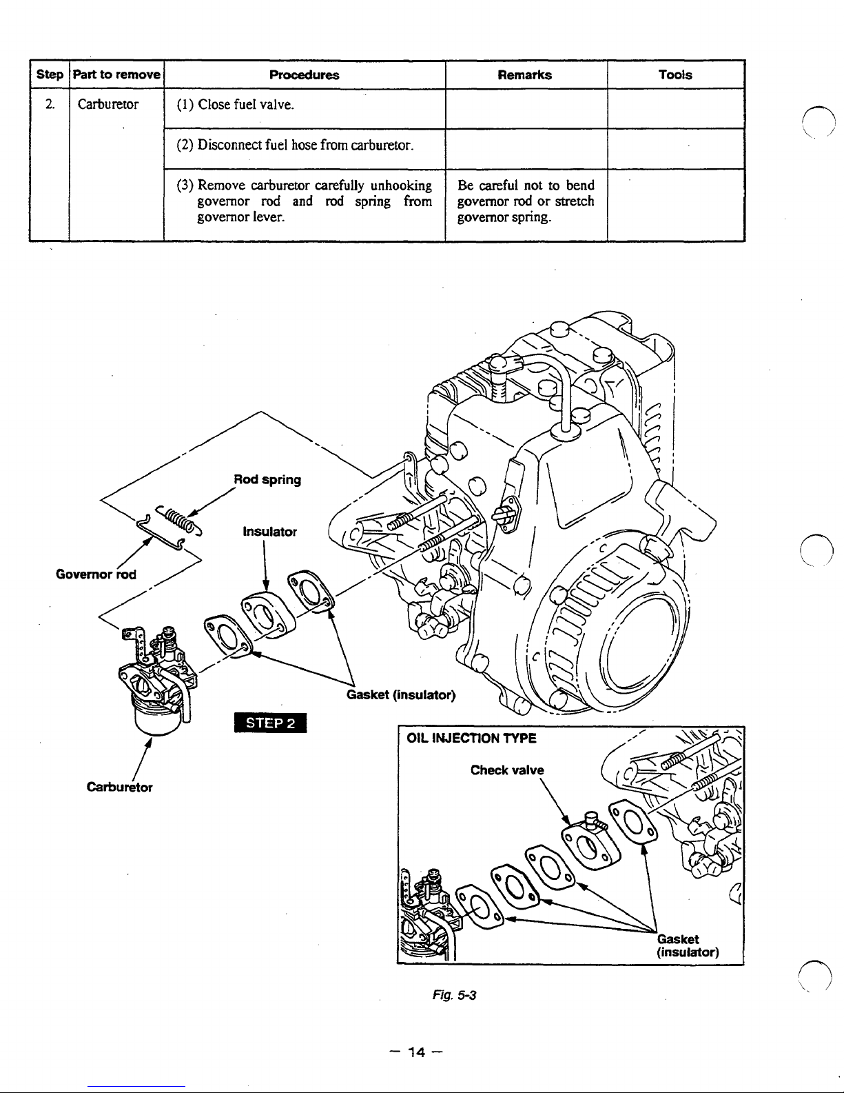
Part
to
remove
Procedures
1
(2)
Disconnect fuel hose
(3)
Remove carburetor carefully unhooking
governor
governor lever.
I
rod
and
from
rod
carburetor.
spring
from
I
Be careful
governor
governor
I
Remarks
not
rod
or
spring.
to
bend
stretch
Tools
I
Carburetor
I
-
OIL
lNJECTlON
Fig.
14
-
TYPE
(insulator)
5-3
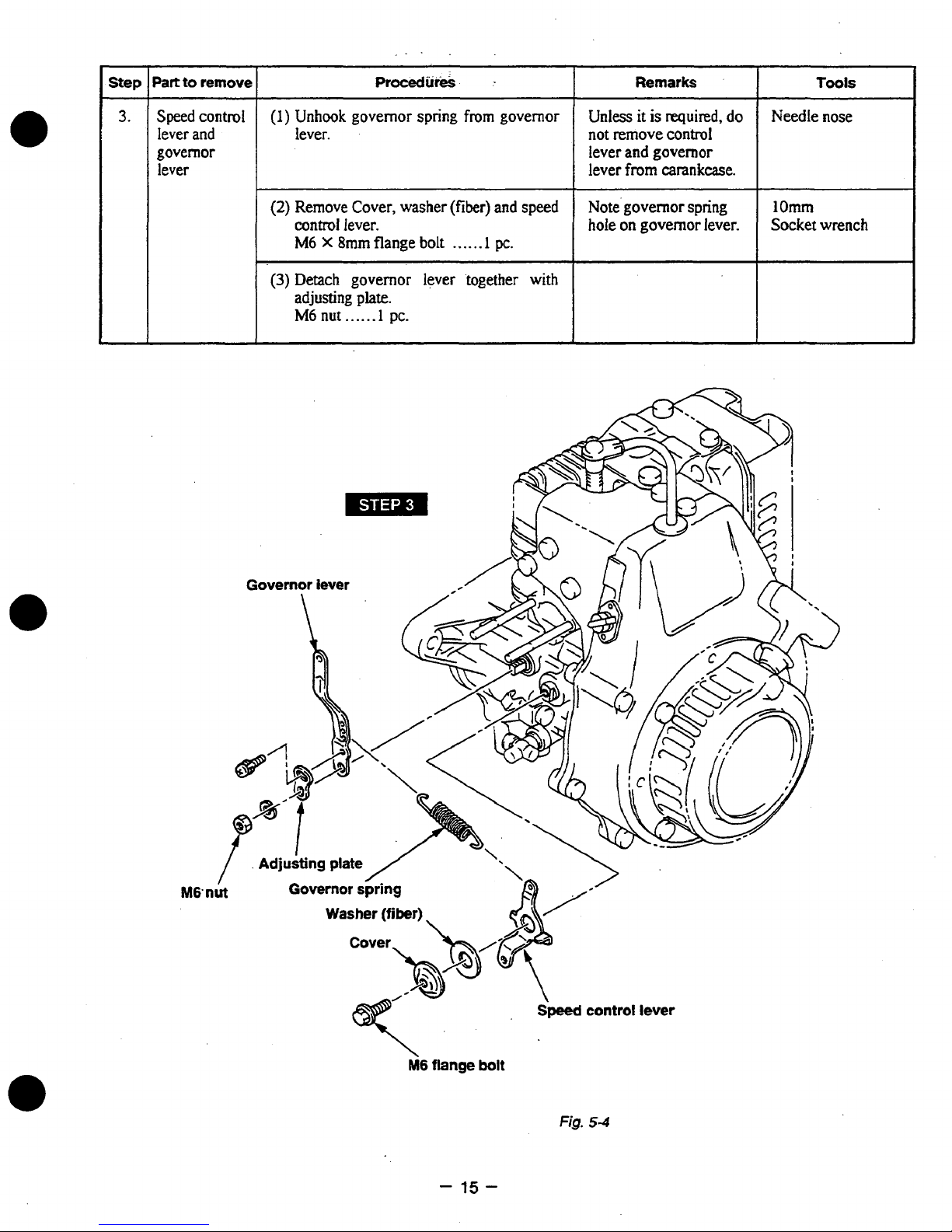
Page 18
%art
to
remove
ProcedureS
:
Remarks
Speed
control
lever
and
governor
lever
(1)
Unhook governor spring
lever. not
(2)
Remove Cover, washer
control
M6
(3)
Detach governor lever 'together with
adjusting
M6
X
8mm
nut
lever.
flange bolt
~~ ~
plate.
. . ..
.
-1
PC.
from
(fiber)
......
governor
and
1
pc.
speed
Unless
lever
lever
Note'governor spring
hole
it
is
required,
remove
on
and
governor
from
carankcase.
governor
control
do
lever.
Needle nose
1
1
Omm
Socket wrench
M6
-
15-
Fig.
5-4
Page 19
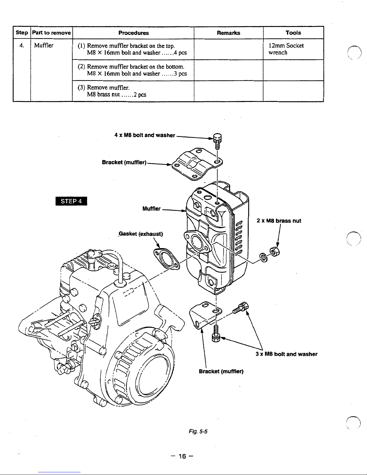
%art
to
remove
Muffler
Procedures
Tools
Remarks
~~ ~
(1)
Remove muffler bracket
on
the
top.
12mm
Socket
M8
X
16mm
bolt
and
washer
. .
..
.
.,4
pcs
wrench
(2)
Remove muffler bracket
on
the
bottom.
M8
X
16mm
bolt
and
washer
......
3
pcs
(3)
Remove muffler.
M8
brass
nut
......
2
pcs
fig.
5-5
-
16-
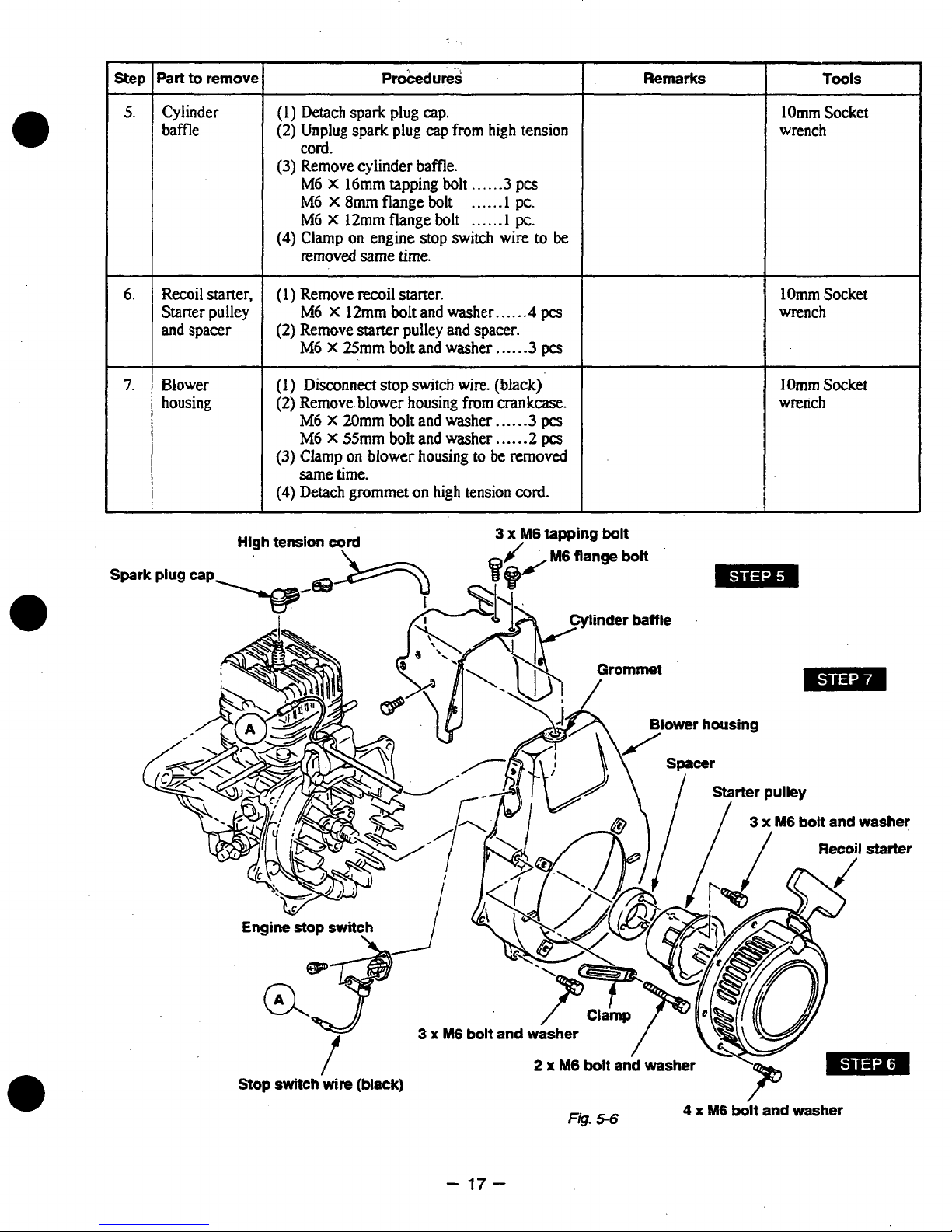
Page 20
Step
Part
to
remove
PtO&d"&!.
Remarks
Tools
5.
Cylinder
Recoil starter.
6.
Starter
7.
Blower
housing
pulley
(I)
Detach spark plug
(2)
Unplug spark plug cap
cap.
from
cord.
(3)
Remove cylinder baffle.
M6 X 16mm tapping
M6
X
8mm
flange
M6 X 12mm flange
(4)
Clamp
removed
(1)
Remove recoil starter.
(2)
Remove starter pulley
M6
(1)
(2)
Remove blower housing
M6
on
engine stop switch wire
same time.
X
12mm
bolt
X
25mm bolt and washer
Disconnect
X
stop switch
20mm
bolt
M6 X55mmboltandwasher
(3)
(4)
Clamp
Same
Detach
on
blower
time.
grommet
bolt
bolt
bolt
and washer
and
wire.
and washer
housing
on
high tension
high tension baffle
.....
......
......
spacer. and spacer
from
to
be
(black)
.3
pcs
1
pc.
1
pc.
to
be
......
4
pcs
.....
-3
pcs
crankcase.
.....
-3
pcs
......
2pcs
removed
cord.
lOmm
Socket
wrench
1
Omm Socket
wrench M6
I
Omm
Socket
wrench
-
17-
Page 21

'art
to
remove
Ignition
coil Remove ignition coil.
M6
X
20mm
Procedures
bolt
and washer
Remarks
,.
.
. .
.2
pcs
lOmm
wrench
Tools
Socket
Flywheel
Oil
L
pump
(1)
Remove flywheel nut. 19mm Socket
MI4
nut
and
spring
washer
(2)
Remove flywheel
(See Fig.
(3)
Remove the key from crankshaft. Be careful
(1)
Remove the body
crankcase.
M6
(2)
Take
which
5-8.)
X
20m bolt
out
fixed
the clip of
at
the
using
and
crankshaft.
. .
....
1
PC.
flywheel puller. Flywheel
of
oil
pump
washer
the
.
. . .
.
pump
from
.2
pcs
gear
can
removed
head
of
with
the
by
of
the center bolt
the flywheel puller
hammer.
key.
easily
striking
not
to
be
the
lose
wrench
Flywheel puller
209-95004-07
U
OIL
INJECTION
TYPE
Fig.
2 x M6
5-9
bolt
and
washer
-18-
Flywheel
I
-
Fig.
5-7
M14
flywheel
I
nut
Page 22

Step
1
I.
Part
to
remove
Cylinder
head
PTOCedUreS
(I)
Remove spark plug.
(2)
Remove cylinder head.
MSX35mm
*
2
pcs
bolt and washer
on
muffler side
are
.
. . .
-.
*4
special
-
pcs
bolt.
Remarks
Champion
NGK
Gasket, between
cylinder head and
cylinder.
US
BM6A
Tools
21
mm
Plug wrench
12mm
wrench
socket
4
12.
x
M8
bolt
Spark
and
Cylinder
Remove cylinder. Cylinder
M8
nut
......
4
pcs
plug
x
M8
/
head
p=
special
bolt
s-
I
\@
12mm
socket
wrench
GaskG
Cylinder
4xM8nut
BID
-
19-
Fig.
5-70
Page 23

Step
13.
Part
Piston
piston
to
remove
and
pin
Procedures
(1)
Remove
(2)
Remove piston
clips.
pin
to
remove piston
needle bearing.
(3)
Remove piston rings from piston.
and
Remarks
Be
careful
not
damage piston.
Be
careful
the
too
rings
by
much
or
not
twisting.
to
to
break
spreading
~~~ ~
Ring
expander
Piston
ring
~
-
20
Fig.
-
5-1
1
Page 24

14.
Crankcase
Remove
crankcase
and
M6
bolts
2
governor
X
40rnrn
M6 X 55mm
Procedures
fastening crankcase
1
together to remove crankshaft
sleeve
bolt
and
bolt
washer..
and
washer
. . . .
-. . . .
2pcs
.3pcs
and
Tools
1
Omm
Socket
wrench
Governor
plate
\
Governor
sleeve
bolt
and washer
-
21
-
2 x M6
Fig.
5-72
bolt
/
and
washer
Page 25

6.
REASSEMBLY
6-1
CLEANING
Check all sliding and rotating parts, such as piston, cylinder,crankshaft and bearings for defect.
Wash the disassembled parts
them twice, first time remove visible dirt roughly, and second time using fresh kerosene.
After washing, blow them thoroughly with compressed air.
Do
not wash electric parts. Wipe them with clean cloth and dry them.
Accumulated carbon on the cylinder-head, gasket, piston, cylinder and inside the muffler
carefully removed, and finish the piston with oil stone to get smooth surface.
Parts
of
air.
Check the cable for any damage.
Air-cleaner element shall be washed in
to 4 kerosene and 1 engine oil, and assemble it after squeezed well.
Take special care not to contaminate the parts with dust and apply mobile oil on the surface
to prevent rust.
6-2
CHECKS
After disassembling and cleaning the engine parts, check them and, if necessary, correct them according
to the section"CLEARANCE DATA
pipes shall
BEFORE
REASSEMBLY
in
kerosene to remove dust, dirt and contaminated oil thoroughly.
Wash
to
carburetor to be washed carefully with gasoline and blow them thoroughly with compressed
the
detergent and dry thoroughly. Then put it to mixture of
in
order
AND
CORRECTIONS BEFORE REASSEMBLY
and
be
replaced with new ones.
LIMITS
/
TORQUE
SPECIFICATIONS."
Gaskets and rubber
be
2
\.
I'
6-3
PRECAUTIONS
(1)
Clean
crankshaft, connecting rod and bearings.
(2)
Take care not
(3)
Check lip of oil seals. Replace oil seal if the lip
Apply
(4)
Replace all the gaskets with new ones. Use only designated sealing agent.
where packings or sealing agents are used.
(5)
Replace keys, pins, bolts, nuts, etc., if necessary.
(6)
Be sure to assemble those parts provided with alignment marks by bringing the marks in alignment.
(7)
Tighten
tighten them to torque readings appropriate to'the size.
Standard Tightening Torque for screws are as
If small screws are over torqued, they may get broken. When tightening several screws fastening
single part, tighten them all evenly, by alternately tightening diagonally located parts.
(8)
Apply oil to rotating and sliding parts.
(9)
Check and adjust clearances and end plays where specified in this manual.
(10)
During the assembly,
(11)
After the completion of reassembly, turn the engine by hand and check if there is any disorder or
loose members.
parts
oil
to
bolts,
6mm
gmrn
IOmm
.............................
.............................
.............................
FOR
REASSEMBLY
thoroughly before reassembly. Pay most attention to cleanliness of piston, cylinder,
to
contaminate the
the
lip before reassembly.
nuts and screws to the correct torque specified. When there is no torque specification,
parts
with dust during reassembly.
is
damaged.
Do
not apply oil to parts
follows:
90
turn
the moving part
250
370
kgf-cm
kgf-cm
kgf-cm
(6.5
ft. Ib)
(18
ft. Ib)
(26.7
ft. lb)
by
hand to check for friction and noise.
a
0
'\
1
n
'.
,)
-22-
Page 26

6-4
REASSEMBLY
6-4-1 CRANKCASE1
(1)
Before reassembling the crankcase, check bearing and
If
there
is
any
(2)
Put crankcase 2 with mounting flange down on a firm stand
PROCEDURES
damage, replace them with
new
ones.
installed.
(3)
Apply oil to the bearings of crankcase and ascertain that there
(4)
Put governor plate
Place the notch of governor plate to cylinder
(5)
Assuring that knock pin
crankshaft with press (or
and
governor sleeve
on
tap
it with a
on
crankshaft
soft
the
bearing of crankcase
(or
spark plug)
and
notch
hammer) taking
oil
seals.
so
that crankshaft move freely when
is
no
warp
on
the lip of oil seals.
2.
side.
on
governor plate are aligned, assemble the
care
not to damage the oil seal.
it
is
Governor
sleeve
-
23
Fig.
-
6-1
Page 27

6-4-2
ADJUST
CRANKSHAFT
END
PLAY
Select one spacer
so
that
the
crankshaft end play
to
be
0-
0.2mm(0”-
0.008
’
)
SPACER
THICKNESS
0.1
(0.004”
)
P/N
161-25001-03
0.3 (0.012”
)
P/N
161-25002-03
Crankcase
2
Crankcase
1
Fig.
6-2
6-44
CRANKCASE
2
(1)
Clean
the
join
of
both
crankcases and apply sealing agent (THREE
BOND
1215
or
equivalent).
Joint crankcase
1
with
press (or tap
it
with a
soft
hammer). Fasten
them
with
bolts.
M6
X
40
bolt and washer
Ass’y.
* *
2
pcs
M6
X
55
bolt and washer
Ass’y-
-
-
3
pcs
88
-
9.8
N
m
90
-
100
kgfocm
6.5
-
7.2
ft
Ib
CAUTION
:When reassembling
the
crankcase,
tighten the
diagonally
located
pairs
of
bolts
according
to
the specified tightening torque.
NOTE
:
After
reassembling the crankshaft
to
the
crankcase, check
if
the
crankshaft
rotates
smoothly.
0
‘\
.
’
-
24
-
Page 28

6-49
If
then spread the ring only
PISTON
an expander
RINGS
is
unavailable,
far
install
enough
the ring
to
slip over the piston and into
by
placing the open ends
of
the ring
the
correct groove.
on
first
land
of
piston,
CAUTION
E
\
/
:
1)
Be extremely careful not
2)
Put
the
(This
3)
Assemble
Top
ring
Second ring
is
open
to
ends
prevent
the
rings in
.---.-...-
------
f"\
I
Open Ends
Fig.
6-3
of
Piston
to
distort
of
piston rings
the
rings
the
from
order
Chromium
Parkerized surface
and break
to
the
rotation while operating
of
the
plated
surface
(looks
\
Ring
the
ring.
lock
pins in
second ring and then
(looks
the
white
grooves.
the
top
silver
dark in color)
lop
ring
Key
stone
Chromium
Plain
type
Parkerlrized
Second
engine.)
ring.
in
color)
type
plated
ring
-
25
-
Page 29

6-44
1)
2)
PISTON
Position the
with the needle bearing by gently striking the piston pin.
CAUTION : Apply oil to the needle bearing before reassembling
Assemble piston pin clip.
“F”
mark
of
piston top to flywheel side and reassemble the piston and connecting rod
it
to piston pin.
rl
0
CAUTION : Replace piston pin clip
3)
Be sure that piston and connecting
646
1)
2)
3)
4)
CYLINDER
Clean carbon deposit
CAUTION
Wipe oil from crankcase
Replace cylinder gasket with a new one.
Placing open ends
NOTES
:
If
carbon deposits are not removed
be
:
(1)
Apply
(2)
Mark
(3)
After assembling cylinder make
from
damaged
joint
of
piston
oil
to
sure
that
cylinder head and combustion chamber.
when reassembling.
surface
rings
piston
intake
M8nutandwasher
I
TIGHTENING
17.6
-
180
-
13.0
-
TORQUE
215
Nom
220
kgf
-
159.ft-Ib
I
cm
if
there
rod
move smoothly after reassembled.
and
to
the
lock
and
piston pin before reassembling.
and
exhaust
----.----
is
any looseness after reassembling
the
piston and inner
apply sealing agent
pins in the grooves. Install piston to the cylinder.
ports
are
facing
sure
the
crankshaft
4pcs.
(THREE
the
right
rotates
surface
BOND
side
smoothly.
it.
of
1215
or equivalent).
cylinder may
-
26
-
Page 30

0
6-4-7
1)
2)
CYLINDER
Clean carbon from combustion chamber and dirt from between the cooling fins
Check its mounting face for distortion.
Use
new
cylinder head gasket.
HEAD
of
cylinder head.
NOTE
3)
Install the cylinder head
M8
NOTE
I
Cylrider head
X
35
mm
bolt and washer
:
Special
~~~~ ~ ~~
17.6
-
21.5 N-m
180
-
220bf-cm
180
-
15.9
bolts
ft*
gasket
so
are
Ib
must
be
placed folded edge
that the alignment marks on the cylinder head and cylinder match.
*
- * -
4pcs.
to
be
instak?d
on
the mumer
side
up.
of
the
roward
cylinder
cylinder head)
head.
Fig.
6-5
6-44
Check Carbon deposits and wear
Replace spark plug with a new one
SPARK
Spark Plug
I
I
NEW
11.8
-
120
-
8.7
-
PLUG
:
CHAMPION
NGK
SPARK
14.7
10.8
BM6A
TIGHTENING
PLUG
N
150
kgfecm
ft
-
m
on
U8
TORQUE
I
Ib 18.0
the spark plug terminal.
if
necessary.
or
REllGHTENlNG
24.5
-
29.4
N
-
m
250
-
300
kgf
cm
-
21.7
ft
-
Ib
I
I
-
27
-
Page 31

64-9
1)
2)
OIL
PUMP
Worm gear
Mesh each gear at the proper position,
secure with C-clip.
Put grease
(equivalent to Shell Albania
After assembling pump,
be rotated a few times by hand to be spread the
grease.
How
to eliminate air from oil tube
Remove
Allow
out the remaining air.
After checking, reassemble the tube to the
inlet, then clamp securely.
the
the tube to
on
tube
(OIL
INJECTION
drive
from
fill
TYPE)
worm
gear about
#3)
the
crankshaft should
oil pump inlet.
with
oil, which will force
0.5
then
cc
fig.
r'
6-6
.
6410
1)
2)
3)
CAUTION
FLYWHEEL
Wipe
Put the
Install
off
the
M14
Nut with spring washer-
I
TlGfiTENlNG
:
1)
When air is
size will result.
2)
When air
Then
system. After running
No
oil
and
woodruff
flywheel to the crankshaft. Tighten the nut with spring washer.
mixed fuel/oil must be used
need
grease thoroughly from the tapered portion
key in the key way
TORQUE
in
is
observed
to
I
the
*
-
oil
tube, insufficient oil will
- -
in the
of
1
PC.
tube,
1
mixed
crankshaft.
air must
fuel/oil
be
be
eliminated by
until
air has been eliminated
tank,
you
of
the crankshaft and flywheel.
carried to the engine
the
above procedure.
may continue with gasoline only.
and
from
engine
entire
I
-
28
-
Page 32

6-4-1
1
IGNITION
COIL
When installing the ignition unit
on
the crankcase, use a non-metallic feeler gauge to measure the air gap
,
its hold down screws.
between the ignition coil and flywheel. The ignition coil
can
be moved to adjust the air-gap
by
loosening
M6
X
20mm
bolt and washer
-
*
-
- - -
2
pcs.
1
AIR
GAP
0.3
-
0.5mm
0.012
-
0.020
in
Fig.
6-7
6412
BLOWER
HOUSING
Through high tension
cord
from
inside the blower housing and put the .grommet
on
the cord to
the
blower
housing. Then install the blower housing
to
the crankcase. A clamp is fastened together
on
the air cleaner
side bolt.
M6
X
20mm bolt and washer
-
-
*
*
-
-
3
pcs.
M6
X
55mm bolt and washer.
- - -
-
2
P-
64-13
RECOJL
STARTER,
STARTER
PULLEY
AND
SPACER
I)
Install spacer and starter pulley
to
the flywheel.
2)
Install recoil starter. Make sure the recoil
knob
is pointing the right direction.
M6
X
25mm
bolt
and washer
- -
3
pcs.
M6
X
12mm bolt and washer
- - - -
-
4
pa.
64114
CYLINDER
BAFFLE
A
clamp
is
fastened together on the air cleaner side
of
the cylinder baffle.
M6
X
16mm tapping bolt
-
- * -
-
- - -
3
pcs.
M6
X
12mm flange bolt
- - - -
- - - -
I
PC.
M6
X
8mm
flange bolt
- - - - - - - -
*
-
I
PC.
6415
.MUFFLER
1)
Replace muffler gasket with a new one.
2)
Install muffler and muffler bracket. First temporary tighten nuts
and
bolts
on
the muffler
and
the
bracket.
Then
tighten the
nuts
on
?he muffler and the
bolts
on the bracket.
M8
brass nut
and
spring
washer
- - - - - - -
-
-
-
2
pcs.
M8 X 16mm
bolt and spring washer
- -
-
-
-
-
7
pcs.
-
29
-
Page 33

6416
SPEED
CONTROL
LEVER
AND
GOVERNOR
LEVER
1) Install governor lever
to
governor shaft with adjusting plate being temporary tightened.
M6nutandspringwasher-.-.----.--.-..-
1
PC.
M4
X
8mm
screw and spring washer
-
- -
-
1
PC.
2)
Install governor control lever, washer (fiber) and cover
to
the
crankcase
in
this sequence.
M6
X
8mmflangebolt
-.-....-..........
1
PC.
3)
Hook
governor
spring
to
the governor lever and speed control lever.
Governor lever
M4
screw
and spring washer
Speed
control
lever
Fig.
6-8
-
30
-
Page 34

6417
1)
2)
3)
CARBURETOR
Install packing and insulator
Connect governor lever and throttle lever
install carburetor together with air cleaner base plate.
M6selflocknut
Install air cleaner bracket.
M6
X
12mmboltandwasher---.--..--... 3 pa.
AND
AIR
CLEANER
to
the cylinder. Replace packing
........................
on
with
a new one.
the
carburetor by governor rod
2
pa.
and
rod spring. And then
6-4-18
Refer
6-4-19
1)
2)
GOVERNOR
to
section
WIRING
Connect wire from stop switch
Connect spark plug cap
-
End
of
the reassembly
ADJUSTMENT
“7-2
Governor Adjustment”
to
high
-
and
primary
tension cord then plug it
wire
from
ignition coil. Clamp wire to cylinder baffle.
to
spark plug.
-
31
-
Page 35

6-5
BREAK-IN
An
engine that has been completely overhauled by being fitted with a new piston,
assembly
should
Good bearing surfaces
operating the engine under reduced speed and loads for a
While the engine
OPERATION
be thoroughly
and
running clearances between the various
is
being tested, check
BREAK-IN
for
oil leaks.
before being put
short
back
period
into service.
parts
of
time.
Make final carburetor adjustment and regulate the engine operating speed.
Load
I
%PS
%PS
1
1
2
2
3
3
4
4
5
5
1.5
1.5
3.0
3.0
Hp
Hp
Hp
Hp
Load
No
No
No
No
No
No
or
or
or
or
load
load
load
load
load
load
40%
40%
75%
75%
Load
Load
Load
Load
Table
Table
Engine
Engine
61
61
2500
2500
3OOo
3OOo
3600
3600
3600
3600
3600
3600
Speeed
Speeed
rpm
rpm
rpm
rpm
rpm
rpm
rpm
rpm
rpm
rpm
I
Time
Time
IO
min
IO
min
10
min
10
min
10
min
10
min
30
min
30
min
60
min
60
min
rings
can
only be established
.
.
and crankshaft
by
.-
NOTE : Use
25
:
1
Oil
fuelmix
for
break-in
period.
-
32
-
Page 36

7.
-GOVERNOR
0
7-1
CONSTRUCTION
A
centrifugal flyweight type governor
installed
As
changes its opening angle and moves the governor sleeve, which in turn rotates the governor shaft
through the governor
and this governor lever is connected to the carburetor throttle lever through the governor rod at the other
end
When the crankshaft speed increases, all the relevant' members move in the direction indicated
C
marks and the carburetor throttle valve
speed and output. When the crankshaft speed decreases, the same members move
indicated by
recovering the failing speed and output.
in
the crankcase, and lubricated
the engine speed fluctuates, flyweights on the governor plate, rotating together with the crankshaft,
;
thus the throttle valve
r)
marks and the carburetor throttle valve
AND
yoke.
The governor lever is connected
is
OPERATION
is
used. The governor plate, governor sleeve and governor yoke are
by
the oil mixed fuel.
to
the extending part
opened or closed and engine speed and output are controlled.
closes,
reducing the fuel supply and consequently reducing the
opens,
increasing the fuel supply and consequently
of
the governor shaft
in
the direction
by
-
33
Fig.
-
7-1
Page 37

7-2
GOVERNOR ADJUSTMENT
The
governor system should be adjusted
1)
Connect governor rod and rod spring to carburetor throttle lever and governor lever, then install
at
reassembly
by
the following procedures.
governor lever to governor shaft.
NOTE
2)
Connect govemor lever and control lever
And the governor adjustment
a)
Attach the governor lever
:
Never tighten
plate, governor lever
the
on
set screw for the adjusting plate
and
governor
with
is
to be made in the following sequence:
the governor shaft.
b)To the governor shaft, fasten temporarily the
adjusting plate with nut and spring washer.
c)To
the governor lever, fasten temporarily
adjusting plate with screw
At
this
moment, the adjusting plate is free to
(1)
and nut
(2).
move. (See Fig.7-2.)
Push
d)
the adjusting plate clockwise.
(See Fig.7-3.)
e)
Set the governor lever
tighten the screw
(1)
at
the high position and
and nut
(2).
(See Fig.7-4.)
at
this
time,
and do
not
fix
adjusting
shaft.
governor spring, and install control lever to crankcase.
the
fig.
7-2
/
7-3
HIGH
7-3-1
Unless required
related parts from.
crankcase. (See
SPEED
WHEN
ADJUSTMENT
NO
TACHOMETER
in
the process
crankcase.
Fig.7-5.)
IS
AVAILABLE
of
disassembling,
If it is necessary
Fig.
7-4
do
not remove governor control lever and
to
remove them, never turn high speed stop bolt on
-
34
-
/
or
other
Page 38

7-3-2
WHEN A TACHOMETER
IS AVAIL;;ABI;E
i
1)
Install control lever and other related parts.
2)
By
turning control lever with governor spring
on
it, gradually increase the engine speed up
to
3)
Locate high speed
stop
bolt
on
the control lever and lock it
so
they it will stop control lever against
specified engine speed.
the stopper plate.
Make sure that the governor spring
is
hooked
in
the same hole
on
the governor lever
as
original.
There are
3
holes
on
the governor lever.
Normally, hook governor spring in the center hole.
Governor
lever
"-
"
Speed
control
lever
Fig.
7-5
-
35
-
Page 39

8.
MAGNETO
EC12
ignition divice which utilizes the power transister as an element for controlling electric unit.
This
efficiency because
mechanical parts.
8-1
This
As
ignition coil with built-in transistor, and lead wires to spark
engine is equipped with a pointless Solid State Ignition system. This is a circuit breaker type
system' is free from start-up failure due to dirty,
of
moisture, rough breaker point surface and incorrect timing resulting from worn
OPERATION
system is referred
illustrated
OF
in
Fig.S-l.,
Connector
ME
IGNITION
as
T.C.I.
this
SYSTEM
(Transistor Controlled Ignition) system.
is
a simple system, consisting
IGNITION
Black
COIL
Ignition
WITH
burnt
BUILT-IN TRANISITOR
Coil
plug
1
or
oxidized point surfaces, low ignition
of
a flywheel with magnetic fields,
and stop switch.
Spark
k
Plug
an
n
,.,
/
al
TST
Stop
Switch
Fig.
&I
Magneto
WRING
;
Flywheel
DIAGRAM
SOLID
STATE
IGNITION
-
36
-
Page 40

8-1-1
PRfNCIPLE
1)
Rotation
By this voltage, electric current
2)
With further rotation
flows
current
11’
3)
With further move rotation
it
(collector) and E (emitter) Terminals of signal transistor. Current
which induct SCR.
4)
Current
This
through power transistor base terminal
(b)
did.
passes its peak. Current
(h)
current change causes high voltage on secondary coil which produces sparks at spark plug.
OF
THE
OPERATION
of
the flywheel generates a voltage
(11)
flows
of
the flywheel, electric current
and
(14)
in
signal transistor. The current
of
the flywheel, the current generated by primary coil starts to decrease
(Is)
starts flowing because there is
turns into current
(16)
with induction
on
the primary side
and it charges condenser.
(h),
(B).
This actuates power transistor and results electric
(14)
charges the condenser reversely as the current
of
the
SCR,
of
the ignition device.
which is reversed of electric current
no
electric potential difference in the
(Is)
this cuts
flows into the gate
off
anent b abruptly.
(G)
of
(h),
as
C
SCR
0
Fig.
8-2
8-2
IGNITION
In
the event of malfunction of the ignition
Broken, frayed, loose
Faulty spark plug-wet, dirty, insulation broken
If difficulty
should be checked
Remove spark plug-then with the ignition cable connected to it, lay the spark plug
part
of
the engine
the recoil starter.
trouble.
1)
2)
Using a
ignition lead and the engine stop switch wire.
This resistance reading should
infinite, this indicates open winding in the ignition unit, a loose
failed high tension lead.
If a very low reading
itself is determined to
If
Check to make sure that the external magnet, mounted
Since the solid state ignition unit
secondary coil resistance..
good
SYSTEM
is
experienced in starting the engine or if engine misfires,
:
so
If
there is
a
quality ohm-meter, check the secondary coil resistance between the plug terminal of
CHECK
system,
or
disconnected ignition wires.
check the following first:
or
incorrect plug gap.
the
that the gap can be observed as
a good strong spark occurs, the ignition system
weak
spark or no spark at all, check the ignition system as follows:
is
self-contained, the only testing which
be
approximately
is
taken,the secondary coil
be
faulty, then it will
have
you
rotate the crankshaft several times by means of
on
the flywheel is in a good condition.
10,000
is
to be replaced.
to
probably shorted.
12,000
can
ohms.
or
broken spark plug connector or
If,
strength
be eliminated as the source
can
If
the
after testing, the ignition unit
of
the ignition spark
on a convenient metal
be performed
resistance reading
is
on
the
the
of
is
a
-
37
-
Page 41

9.
CARBURETOR
9-1
FLOAT
CARBURETO'R
9-1-1
1)
The float chamber
body and, with a float and a needle valve,
OPERATION
FLOAT
SYSTEM
is
AND
CONSTRUCTION
located below the carburetor
main-
tains a constant fuel level during engine operation.
Fig.9-2.)
(See
The
fuel
flows
chamber
to
through
a
specific level, the float rises,
from
the fuel
tank
.into the
float
needle valve. When the fuel rises
and
when
its
buoyancy and fuel pressure are balanced, the
needle valve closes to shut
off
the fuel, there
by
keeping the fuel at the predetermined level.
PI1
Fig.
9-2
-
30
-
Page 42

2)
PILOT
The pilot system feeds the fuel to the engine
The fuel is fed
the pilot
The fuel-air mixture
At idling speed,
3)
MAIN
The main system feeds the fuel to the engine at medium and high-speed operation.
The fuel is metered
mixed with the fuel through the bleed holes in the main nozzle, and the mixture is atomized out
main bore. It
which
4)
CHOKE
The choke is used
choke, the negative pressure applied to the
starting
SYSTEM
through
air
jet.
the
SYSTEM
is
mixed again with the air taken through the air cleaner into an optimum fuel-air mixture,
is
supplied
up
the engine more
to
during
the main jet to the pilot jet, where it
is
fed to the engine through the pilot outlet and the bypass.
fuel is
by
the engine.
for.
mainly
the main jet
easy starting when ' the engine is cold. When the starter
fed from
and
fed
the
to
main
idling and low-speed operation.
is
metered and mixed with the air metered by
pilot
outlet.
the main nozzle. .The air metered
nozzle increases and draws more fuel accordingly thus
easily.
by
the main air
is
operated with a closed
jet
of
is
the
-
39
-
Page 43

9-1-2
DISASSEMBLY
AND
REASSEMBLY
A
part from mechanical failures, most of the
carburetor troubles are caused by an incorrect
mixing
ratio, which may arise mainly due to a
clogged
up
air
or
fuel passage in the jets,
or
fuel
level variations.
In
order to assure proper
flow
of
air
and
fuel,
the
carburetor must be kept clean at all times.
The carburetor disassembly and reassembly procedures are
as
follows : (See Fig.9-3.)
1)
THROTTLE
SYSTEM
a)Remove the Phillips screw
(1)
and throttle
valve
(2),
and
pull
out the throttle shaft
(3).
b)The spring
(4)
can
be taken out
by
removing
the
throttle stop screw
(5).
*
Be
careful
not to damage the throttle valve
ends.
2)
CHOKE
SYSTEM
a) Remove the Phillips screw
(6)
and choke valve
(7),
and pull out the choke shaft
(8).
b)
When reassembling the choke shaft, make sure
that the cutout in the choke valve
faces
the
main air jet.
3)
MAlN
SYSTEM
a)Remove the bolt
(9)
and take out the float
chamber body
(10).
b)From the body remove the main nozzle
(11)
and then remove the main jet
(12)
from the
main nozzle
(11).
a)Fasten the main jet securely to the body.
Otherwise, the fuel may become too rich and
cause engine malfunction.
c)
Reassembly
b)The
bolt
tightening torque is
5
ft
lb
6
17
3
1
13
10
Fig.
9-3
n
'\
,)
(7Okgf-cm). Be sure to set
the
gasket
(13)
and
washer
(14)
for chamber
(10).
4)
FLOAT
SYSTEM
a) Pull out the float
pin
(15)
and remove the float
(16)
then the clip
(17)
and needle valve
(18).
CAUTlON
:
When cleaning the jets, use neither a drill
nor
a
wire (because
of
possible damage
to
the orifice
which
will adversely affect
fuel
flow).
Be
sure
to
use
compressed
air
to blow them
clean.
b)When
removing
the
needle valve and float, gently tap
on
the reverse side
using
the rod more slender
than the float pin and remove, since
the
float pin
is
calked to the carburetor body.
-
40
-
Page 44

9-2
DIAPHRAGM
CARBURETOR
9-2-1
1)
OPERATION
PUMP
AND
CONSTRUCTION
The diaphragm of the fuel pump is moved by
pressure fluctuations
in
the engine crankcase.
When it moves towards the engine, the inlet valve
(E)
of the pump opens and the outlet valve
shuts, and the pump sucks
diaphragm swings back, the
and the fuel is forced
A
compensating chamber
out
in
fuel. When the
inlet
valve
of
the outlet valve
(W),
situated between
(E)
the inlet and the outlet valves cushions the
(A)
closes
(A).
oscil-
lations of the fuel flowing past. The diaphragm of
the chamber
sphere fuel pressure builds up,
springs
upwards towards the atmo-
and
contracts again
when the pressure drops.
After the pump, the fuel flows through the fine
filter
(F).
This
traps
residual particles
of
dirt,
but
is
not a
substitute for the large-area filter, which must be
fitted
in the
fuel flow before the carburetor.
2)
PRESSURE
A
diaphragm pressure regulator ensures, almost
REGULATOR
independently of the pump pressure, a constant
vacuum before the jet systems.
If
the vacuum in the carburetor inlet pipe
mitted
moves the regulator lever
(M),
An
to
the pressure regulator via the jets, it
against a spring and
even
flow
of fuel then
(R)
opens
passes
via the diaphragm
the feed valve
through the valve
is
trans-
(N).
into the regulator and through the jets into the
carburetor port. The diaphragm
lever
(R)
and the feed valve
any
to
3)
If
given
HIGH
full power is required
flow
SPEED
quantity.
OPERATION
(M),
the regulator
(N)
constantly adjust
from
the engine, the
throttle valve and choke are fully opened.
The vacuum in the carburetor sucks fuel into
main system via main mixture screw
non-return valve
tem via idle mixture screw
drilling
The fuel
(LA)
flow
(V),
and through the idling
(L),
and the bypass drillings
can be altered by opening and
(H)
the idling outlet
(BP).
the
and the
sys-
closing main mixture screw and idle mixture
screw.
I1
L”7+
Fig.
9-4
3
High
speed
-
41
-
Page 45

4)
MID-RANGE
If
only
reduced engine output is required and the
throttle valve
vacuum
the
gine. The fuel now
system.
main system closes, thus preventing air
tering the pressure regulator, where it could im-
pede the fuel flow.
5)
IDLING
When the engine
far
the engine
(LA).
outlet drilling
drilling
out.
sufficient to
space between the throttle valve and the en-
As
closed that the vacuum between the valve and
While fuel is being sucked out
(BP),
OPERATION
is
accordingly portially closed,
suck
fuel
is
present only
only
a result,
flows
the
non-return valve
through the idling
(V)
from
OPERATION
is
idling, the throttle valve is
only
acts
on
the idling outlet drilling
of
the idling
(LA),
which mixes with the fuel coming
air
is
entering the bypass
in
in the
en-
so
a
N
The
idling speed
and
the matching fuel quantity with idle mixture
screw
6)
To
throttle valve
Each attempt to
uum
through
When starting
must first
must be flushed out of the carburetor systems.
Several attempts at starting-usually
essary before the first firing occurs.
The choke must then be opened and the next
attempt will
(L).
STARTING
start the engine, the choke
in the carburetor
both jet systems.
be
is
set with the stop screw
is
closed, with the
@>
roughly
start
a
hot or cold engine, the carburetor
filled with fuel,
half-open.
the engine produces a vac-
port,
which draws fuel
as
air
and fuel vapour
four,
start
the engine
running.
GAS)
are
nec-
n
-
42
-
Fig.
9-7
Page 46

9-2-2
DISASSEMBLY
I.
A
part from mechanical failures, most of the carburetor troubles are caused
by
an incorrect mixing ratio,
In order
to
assure proper
flow
of air and fuel; the carburetor must
be
kept clean at all times.
The carburetor disassembly
and
reassembly procedures are
as
follows : (See
Fig.9-8.)
which may arise mainly
due
to a clogged
up
air or fuel passage in the jets,
or
fuel level variations.
1)
FUEL
PUMP
a)
Remove the screw
(1)
and
pump
cover
(2).
b)
Remove pump gasket
(3)
and diaphragm
(4).
c)
Inspect diaphragm
(4),
replace
if
diaphragm
d)
Remove strainer
(5).
shows
any
signs
of
wear
and
curing.
2)
METERING
DIAPHRAGM
a) Remove the screws
(6)
and metering chamber
b) Remove metering diaphragm
(8)
and the
gas-
c)
Inspect metering diaphragm
(8)
for
dirt
and
cover
(7).
ket
(9).
foreign matter.
3)
INLET
NEEDLE
VALVE
a) Remove the
screw
(10)
of
metering lever
(11).
b)
Remove metering lever
(ll),
pin
(12)
and lever
spring
(13).
c)
Remove inlet needle valve
(14).
d) Inspect inlet needle valve
(14).
Rubber tip
should
not
be deformed where
it
contacts
the
seat.
4)
MIXTURE
SCREW
a) Remove idle
(15)
and main
(16)
mixture screw
and
washer
(17).
b)
Remove the spring
(18).
c)
Inspect each screw
(15,
16)
for damage, espe-
cially the needle
points
which should have.
no
deformation of the tapered surfaces.
5)
THROTT'LE
AND
CHOKE
a)
Remove the E-ring
(19)
and
the screw
(20)
and
throttle valve
(21),
and pull
out
the throttle
shaft
(22).
b)
Remove
the
screw
(23)
and
the choke valve
8
7
a
(24),
and pull
out
the choke shaft
(25).
-
43
-
Fig.
9-8
Page 47

9-2-3
Reassembly
and
Adjustment
Replace all
1)
MIXTURE
Install idle and main mixture screws.
a) For the nominal setting, tighten the screws
turns
In
accordance with the actual operation and fuel consumption condition, adjust the screws
2)
INLET
a)
Inspect
Assemble the lever onto the pin and rotate the
worn
with new ones. Make sure to clean all
parts
before reassembly.
SCREW
fulIy
and
then turn back counterclockwise at the following
;
Idle mixture screw Main mixture screw
2
turns
Turning
NEEDLE
the metering lever
back
for
nominal setting
One
turn
VALVE
the
and
the
Fig.
pin.
9-9
1
and
112
turns
Turning direction
air
fuel ratio adjustment
for
pin.
a
The lever should be
should
b)
Install the inlet needle valve, metering
metering lever,
c)
The free end of the metering lever should
to
gasket flange
If
the free end of the lever, then carefully push
down
is
the lever.
not
stick.
pin
0.3
rnm
(0
to
of
carburetor body.
the metering lever
on
the inlet needle. If the metering lever
too
low,
pry
up
(Fig.
9-11)
free fit
and
retaining
0.012”)
is
too
carefully
on
the
pin
and
spring,
screw.
be
below the metering
(Fig.
9-10}.
high,
push
down
on
the free end of
on
0
as
necessary.
Push
down
here
n
V
Then push
down
needle here
Fig.
-44-
9-1
1
Page 48

'
10.
1b-1
(1)
OiI
(2)
Mixture
I
I
OIL
SEPARATE
Idle
Load
NJECTION
I
flow
ratio
I
I
SYSTEM
OIL
INJECTION / FUEL
19
:
1
@
1600
25
to30
:
1
@3800
rpm
rpm
SYSTEM
I
I
10-2
BASIC
STRUCTURE
OF
THE
SEPARATE
OIL
ONJECTION 1 FUEL
2000
Fig.
10-1
SYSTEM
Gasoline
4000
r.p.m.
tank
-
45
F;g.
-
10-2
pTA
:
Gasoline
Page 49

Carburetor
Fig.
10-3
10-3
10-3-1
OIL PUMP OPERATION / FUNCTION
OIL PUMP
(1M64-01)
OPERATING
PRINCIPLE
(1)
The
crankshaft
turns
which rotates the
gear. The plinger which directly gose to the
worm rotates at
(2)
The plinger wilI
by
the spring.
Then
it
moves
motion due
1/17th
to
to
the configuration
be
left
of
pushed
and
engine speed.
down to the pins
right with a rotating
of
the edge
lead.
(3)
The
sub
plunger will be stabilized into the
plug
by
the spring via E ring.
By
above
stroke, pumping will occur.
worm
of
(2)
Oil
outlet
-46-
Fig.
10-4
Page 50

Sub
planger
oil
;nlet
I
Piuriger
V
ring
\
I
/
Pinion gear
Detail
A
&
Cam
top
A
mbase
0'.
90'
190'
270"
360"
'1
Lead
configuration
'1
Development
of
lead
height
(P
view)
Fig.
70-5
-
47
-
Page 51

10-3-2
OIL
INTAKE
AND
DISCHARGE
CYCLE
AT
OIL
PUMP
The plunger rotates
(1)
Intake
The plunger remains in the
The plunger strokes
The volume
of
360
oil
chamber
degree
to
the right.
with
a
closed
is
position.
expanded.
cycle. (Shared area means oil.)
Closed
Cam
top'&
Direction
of
position
Pin
plunger roatating
(2)
Discharge
The plunger
The plunger strokes
The
volume
of
is
raised
oil
to
the
to
the left.
chamber
open position
is
decreased.
Oil
inlet
ir'
/m
Fig.
70-6
by
the
pin.
funger
Cam
Direction
Closed
base
of
position
Pin
'A
plunger
m
top
roatating
piiiq
Fig.
70-7
-
48
-
Page 52

10-3-3
(1)
CHECK
Check valve
This
valve
VALVE
is
AND
composed
seat.
The
ball
is
stabilized
by
overrides the spring at time the pressure
ceeds
prevents air
its
setting load.
from
When
entering into oil tube due
vacuum.
Also
this prevents
oil
from
storage.
(2)
Floating switch
This
floating switch
is
located
FLOATING SWITCH
of a ball and body
a
spring. The
ball
ex-
engine stops, this
to
leaking when long
in
the oil
tank.
Lt
Body
Oil inlet
seat
I
t
Ball
Spring
Fig.
Washer
10-8
1.
Structure of floating
switch
(1)
Float located
(2)
Float
located
above
below
limit
This
illustration
shows on position
-
49
Fig.
-
10-3
-.
due
to
exciting
Page 53

11
-
RECOIL
STARTER
When
Tools
I
(1) Remove the recoil starter
(2) Pull the starter
repairing the recoil starter, disassemble and reassemble according
:
Needle nose pliers screw driver.
1
-{,'DISASSEMBLY
from
the engine.
knob
rope
about
on
the reel with the outlet hole
rope.
Hold the reel with your thumb and pull the
starter rope inside the starter case with a screw
driver. (See Fig.11-1.)
While rewinding the reel, control the rotation
by
holding the starter rope the notch
and pressing the reel with your
12
in.
.
and
(30cm)
pull
to
line
thumb.
out the starter
up
the notch
for
the starter
on
the reel
to
the following procedures.
(3)
Remove the
1.
Center
2.
Ratchet guide
3.
Friction plate
4.
Ratchet
5.
Return spring
6.
Reel
(4)
Untie the starter rope from the
move.
CAUTION
Take
towards the
spring
out
from
quickly
starter
Note
:
If
to
case.
power
section
:
or
parts in
screw
the reel
left
the
the
spHng
1
the
slowly
and
hook.
spring
escapes
1-2.
following
right
Do
may
order.
knob
and re-
turning it slightly
to
remove
not
remove
escape
from
the reel
from
i
housing
refer
the
the
Fig.
11-1
1
2
I
3-
-
50
-
Fig.
1
1-2
Page 54

11-2
REASSEMBLY
(1)
Put
the starter rope through the starter
knob
and tie it as
shown
in
Fig.11-3-1. (Tie the rope
tightly for safety sake.)
Put
the opposite side of the rope through starter
case and reel. Tie it securely as shown
in
Fig.11-3-2.
and put the knot
in
the reel
com-
pletely.
Then apply grease a little to starter shaft and
power spring.
(2)
Check that the spring
is
securely
set
in
the reel.
Adjust the position
of
the inner end
of
the
spring to
0.04
”
-
0.08
(1-
2mm)
from
the reel
bush
so
that
it
hooks
on
the hook
in
the starter
case securely.
The
shape
of
the power
spring
inner end can
be
adjusted with a plier
if
necessary.
(3)
Prior
to
installing
the
reel
in
the
starter case,
wind
the
starter rope in the reel for
2.5
turns
in
the arrowhead direction as
shown
in Fig.11-5.
Then let the
rope
out
of
the reel
from
the
reel
notch. Line up the
hook
on
the
starter case with
the
inner end
of
the
spring
and instal the reel
in the starter case.
Check that the inner end
of
the
spring
is
se-
curely hooked
on
the starter case
hook.
I
0.79 - 1.18
in
0.79
-
1
.f
8
in
Fig.
1
1-3-
1
Fig.
1
1-3-2
1.
position
of
the
per
end
Reel
\
n
of
the
inner
end
7
4.
0.04
-
0.08
in
Fig.
1
1-4
(4)
Hold
the starter rope as shown
in
Fig.11-5.
and
I
turn the reel
4
to
5
times
in
the arrowhead
direction.
Firmly press
the
reel not to allow reverse turn-
ing
and pull
the
starter
knob
to let the starter
rope out
of
the starter case.
Return the
knob’
slowly to let the starter rope
rewind
in
the reel.
(5)
Reassemble the parts
in
reverse order
of
disas-
sembly.
Apply- a small amount
of
lock-tight to
set
screw and torque it.
I
TIGHTENING
TORQUE
I
3.4
-
5.4
N
m
55
kgf
*crn
25.2
-
39.6
ft
Ib
w
Fig.
1
1-5
-
51
-
Page 55

11
-3
CHECK AFTER REASSEMBLY
(1)
Test the operation
and retract properly.
(2)
Pull the starter
If
there
is
once or twice. (See
If the starter rope return
grease or
If it does
(After doing
If the starter rope does not retract, the power spring is
from the first step.
not
of
the recoil starter to
knob
all
the way
starter rope left
Fig.11-1.)
mobile
oil
to rotating and sliding parts.
cure the
so
check that the power spring
problem,
and
in
the groove
is
weak
wind
see
if the rope recoils satisfactorily
check following.
of
the reel, the power spring
or
stops before it completely returns to original position, apply
the
starter rope
is
not
once
or
twice.
over loaded,
not
hooked. Reassemble the recoil starter
by
preceding paragraphs method.)
and
if the ratchets project
is
overloaded. Rewind the reel
,i
114
WHEN POWER SPRING ESCAPES
Make a spring holder
from
a
piece of
the spring assembly over the recess
over
the tension
wire ring-start with the outer loop of the spring and wind
Place
is
holder) and
into
12
the recess
or
tab
for
the power spring-form a ring a little smaller than power spring housing
16
ga.
soft
iron
on
the
reel.
(Fig.ll-4.)
in
the housing.
FROM
wire and twist
in
HOUSING
the
housing,
Carefully press the
the
ends together. Wind the power
in
a counter clockwise direction.
so
that
the
hook
in
the outer
spring
out
Fig.
of
the
7
7-6
spring
loop
wire
of
ring
inside
the
spring
(Spring
I.D.
the
-
52
-
Page 56

12.
TROUBLESHOOTING
For a gasoline engine to start and
1)
A
proper fuel-air mixture
2)
Appropriate compression in the cylinder.
3) Good spark at correct
If
all the three requirements are not met simultaneously, an engine
factors such as
contribute to hard
The
most common
12-1
STARTING
Defects in spark plug
Defects in high-tension
cord
Defects
heavy
Cause
in
magneto
starting.
causes
DIFFICULTIES
time
load
of
1)
2)
3)
If cord is burnt or damaged, replace
ignition coil unit.
1)
2)
run
satisfactorily, the following three requirements must be met:
is
supplied
to
at
starting
engine
ignite
to
the
or
too
troubles
the combustion chamber.
mixture.
long an exhaust pipe
are given below.
Remedy
If
contaminated, wash
remove foreign matters and dry.
If spark plug is broken or lost insulation,
replace plug.
Adjust spark gap to.025 (.65mm)
If
wire
or insulation is broken, replace
magneto.
If magnetism
the magneto maker) or replace
is
weak, re-magnetize (at
in
gasoline,
flywheel.
the
cannot
causing
be started. There are also other
a
high
back pressure,
Preventive measure
1)
Use spark plugs of specified heat range.
Do
not use poor grade
cleaner and avoid dust entry.
2)
Do not
of
insulator may get damaged.
hit
or bend the center electrode
the spark plug at adjusting or the
oil.
Clean
which
air
in
Other defects
system
Gas
leak
gasket or other pans
Defects in piston
assembly
Defects in fuel
system
Defects in carburetor
electric
through head
tank
1)
If
switch is faulty (short circuit), replace or
repair.
2)
If primary wire is grounded to the engine
body, insulate
1)
If head gasket
2)
ff head
3)
If spark plug
4)
If spark plug
1)
If piston is wom,replace.
2)
If cylinder is worn, rebore and use oversize
piston and piston ring.
3)
If piston rings are worn, replace.
4)
tf piston rings are stuck,clean or replace
rings.
1)
Clean clogged
2)
Clean clogged fuel strainer.
3)
If incorrect fuel is poured into
water is
fill
it with correct
4)
When fuel pipe
discharge
1)
If clogged with dust,clean.
2)
If defective, replace.
Clean jets and other orifices, if'they are
clogged.
bolts
mixed,.
air.
it
with insulating tape.
is
defective, replace.
are
loose,
tighten.
is
loose, tighten.
is
defective, replace.
tank
outlet.
drain
tank
completely and
fuel.
is
locked
'
tank
with
or
air,
1
)
Keep air cleaner always clean.
2)
Do not use poor grade
1)
Be sure to use a fitter when adding fuel.
2)
Use mixture (gasoline
fuel.
oil.
25
to
50:
1)
as
-
53
-
Page 57

1
Defects
Q
u
S
2!
Excess load
E
os
2%.
s3
uE
Piston
E'
Rod seized
o
e
12-2
SLOWSPEED
Cause
in
carburetor
Or
Connecting
1)
Start engine
and half open throttle valve.
2)
Remove drain
close fuel cock,repeat starting operation
several
If
fuel overflows, check needle valve seat for
wear. Replace, if necessary.
I
1)
If tension of transmission belt
reduce tension.
2)
If
1)
If piston seizes,repair or replace.
2)
If connecting rod large end or small end
seize,replace.
out
of
order
times
load is still
Remedy
with
fully open choke valve
plug
from crankcase, and
to discharge excess fuel.
is
too tight,
too
heavy,
install
a
clutch.
Preventive
1)
Never close choke valve when engine
warm.
2)
When stopping the engine, run
speed for a while. This practice not only
favorably affects next starting,
improves engine
3)
Clogged air-cleaner results in
airfuel mixture.
Clean
it
thoroughly.
Be
careful clogged carburetor.
measure
life.
I
1)
Do
not
use
poor grade
2)
Use fuel of proper mixing ratio.
oil.
it
but
too
at
1
is
siow
also
rich
Most defects listed
12-3
OVERHEATING
1)
If
2)
carbon
If
the heat range of the spark plug is too cool, replace it with
deposits have accumulated
CHAMPION
3)
If
the air-fuel mixture is too lean, clein jets
Clean the
4)
If the load is
124
POWER
1)
If
the cylinder, piston or piston rings are
piston and piston
2)
If
the carburetor
3)
If
the spark plug
4)
If
combustion gas leaks through
If
the gasket
5)
If
the
magneto
6)
If
the air cleaner
7)
If
the fuel system
8)
If
the oil seals at the crankshaft are
as
causes for starting difficulty are also causes for faulty slow-speed operating.
and
KNOCKING
CT8.
air
cleaner
in
DROP
is
faulty,replace it.
is
also.
excess, reduce it below the specified continuous load.
rings.
is
is
faulty,
is
Replace or clean piston rings
out of order, re-adjust or clean it.
faulty (contamination, gas leakage or faulty insulation), dean it or replace
replace
clogged, clean it.
is
clogged, clean it.
in
the combustion chamber, remove them.
correct
and
other passages in the carburetor.
worn,
the
head gasket, re-tighten the clamping screws.
it.
worn
and
replace them or re-bore the cylinder and
if
they are stuck in the grooves.
the compressed gas is leaking, replace them.
one, i.e.
NGR
fit
BM6A
oversize
it.
or
12-5
EXCESSIVE
1)
If
air-fuel mixture is too rich, clean jets and passages in carburetor.
2)
If
the throttle shaft
3)
If
fuel
is
leaking, re-tighten screws or replace faulty part.
4)
If the engine suffers power
following step
FUEL
of
7-4.
CONSUMPTION
carburetor
is
drop
worn,
replace throttle shaft. (carburetor)
accompanied with excessive fuel consumption, trouble-shoot by
-
54
-
Page 58

13.
INSTALLATION
0
Engine life, ease
depend
installing the engine.
13-1
When mounting the engine, carefully examine its position, the method of connecting it to a machine, the
foundation, and the method
Particularly, when determining
checked, the spark plug
13-2
Fresh air is necessary for cooling the engine and burning the fuel.
In case the engine is operated under a hood or
cause vapor lock,loss
the engine properly.
engine to prevent recirculation of the hot air used for engine cooling, and temperature rise of the
machine.
Keep the engine room temperature below
on
INSTALLING
VENTILATION
~
of
maintenance and inspection, frequency
the way in which the engine is installed. Carefully observe the following instructions for
of
supporting the engine.
its
mounting position, make sure that fuel can easily be supplied and
can
easily
of
power, piston seizure, shorter engine
It
is
necessary, therefore,
be
checked and the air cleaner can easily be serviced.
in
a small room, temperature rise in the engine room
to
provide a duct
50
"c
(122°F)
of
check and repairs, and operating costs all
life,
etc.,
making
or
baffle to
even in the hottest period
it
impossible to operate
guide
cooling air to the
of
the year.
can
13-3
Exhaust gas is
outdoors.
engine power. Thus the inside diameter
length.
EXHAUST
If
a
long
Exhaust pipe
GAS
DISCHARGE
noxious.
exhaust pipe is used in such a case, the internal resistance increases causing
:
Less
Less than
When operating the engine indoors, be sure to discharge the exhaust gas
than
3x11
(9.8
ft) long, pipe inside diameter 30mm
5.45m
(18
of
the pipe must
ft)
long, pipe inside diameter 33mm
be
increased
in
proportion to the exhaust pipe
(1.18
in)
(1.30
in)
loss
of
-
55
-
Page 59

13-4
POWER
TRANSMISSION TO
DRIVEN MACHINES
13-4-1
Take the following notes into consideration.
*
*
*
*
*
*
If
1342
When using a flexible coupling, runout and misalignment between the driven shaft and the engine shaft
must be minimized. Runout and misalignment tolerance are specified by
13-5
When remote mounting fuel
carburetor fuel inlet)
excessive head induces overflow
To
leak at
Make the hose length
BELT DRIVE
V-belts are preferable to flat belts.
The driving shaft of the engine must be parallel to the driven shaft
The driving pulley of the engine
Install the engine pulley as close to the engine
If
possible, span the belt horizontally.
Disengage the load when
no
clutch
FUEL
is
used, use a belt tension pulley or the like.
FLEXIBLE
SYSTEM
COUPUNG
to
avoid air lock and vapor lock,carefully examine diameter and car rature
starting
5
-
50cm
must
tank,
(2
of
be in line with the driven pulley
as
possible.
the
engine.
set
the fuel head (height difference between fuel
-
20
in).
Not
enough
carburetors.
fuel
of
the machine.
head causes a pour fuel supply and the
joints.
as
short
as
possible. Fuel filter must be installed in the fuel system.
of
the
machine.
the
coupling manufacturer.
tank
of
fuel hose, heat trasfer and
bottom and
-
56
\
-
Page 60

14.
CHECKS
After disassembling and cleaning the engine parts,check them, and if necessary,correct them according to
the
correction table.
The correction table applies whenever engines are repaired. Its contents should be thoroughly understood
by those who undertake the repairing.
Its specifications must be abided by to effect correct maintenance.
Following are the terms
1)
CORRECTION
All
operations performed on the engine
performance, consisting
2)
STANDARD
The design dimension
3)
CORRECTION TOLERANCE
The tolerance on the re-finished part dimension
4)
CORRECTION LIMIT
The
limit
on
wear,
bum,
AND
CORRECTIONS
employed
of
in the
repairs, readjustments, and replacements.
correction
table.
parts
for the purpose
SIZE
of
the part without
the part and adjustment, beyond which
and other causes will adversely affect
the
tolerance.
or
on
the
readjusted dimension.
any
dimensional and functional changes, due to
the
normal engine
of
improving or recovering the engine
performance.
5)
USE
LIMIT
The limit,beyond which the
part
is
no
longer usable,due to defects
in
function or strength.
-
57
-
Page 61

14-1
CORRECTION
TABLE
Uuit
:
rnm
(in)
ITEM
Flatness
of
cylinder
~
~
~
Roundness
’
(After rebored)
Cylindricity (After rebored)
Outside diameter
I
Piston in
head
hole
STANDARD
Less
Than
0.1
I
STD
0.S
0.S
STD
0.S
0.S
r-
(0.004)
454 (21260)
654.25
454.50 (21457)
453.96 (2.1244)
454.21 (2.1343)
454.46 (21441)
~
612
(0.4724)
SIZE
(21358)
TOLERANCE
0
0
0
0.01
1
-
0.01
0.01
(0.0004)
5
(0.0006)
(
1
CORRECTION
)
-0.004
)
I
454.1
.
454.40
454.65 (2151
453.86 (21
454.1
454.36 (2.1402)
1
+11.965(0.4711)
LIMIT
0.2
(0.008)
5
1
(2.1
31
9)
(21417)
6)
205)
(2.1
303)
U
Width
of
ring groove
Clearance between piston
ring
and
I
Clearance between piston
and cylinder
I
Frt
piston pin
I
B
cn
Ring width
ii
Piston pin
large
V
piston
~~ ~ ~~~ ~~ ~ ~ ~~~~~
between piston and
O.D.
end
I.D.
2s
Clearance
jS?
large
3Z
pin needle bearing
2
E
-
OS
Small
end
end
between
I.D.
I.D.
groove
and
crank
I
I
1
I
I
I
rod
TOP
(MAX.
WIDTH
(0.0039
1.59
OF
SECOND
1.5 (0.059)
TOP.
SECOND
0.1
-
7.5
(0.059)
4
12
(0.472)
424
(0.945)
4
16
(0.630)
(0.063)
KEYSTONE)
0.25
-
0.0098)
I
I
~~ ~
1
I
-0-003
-
+0.02
0
+
0.04
+0.06
0.05
(0.0002
0.040
(0.0002
~~___~_____
0.008
0.008
0.008
0
0.004
(0.0002
0
+0.011
f+0.0008
(0
(+;::::
-
0.1
-
0.004)
-
0.074
-
0.004)
0.0003
(
0.0003
(4.0001
-0.0003
-
0,022
-
0.0009)
(;0004
)
)
)
L
T
)
)
I
I
I
1.44
1.35
0.15
0.25
~1
I
-0.1
I
611.97 (0.471)
0.055
4
(0.057)
(0,053)
(0.0006)
(0.0098)
0.06
(0.0024)
1.5
(0.059)
(0.0039)
(0.002)
16.02
L
L
(0.631
)
-
58
-
Page 62

Unit
:
mm
(in)
ITEM
Clearance between
end
I.D.
and
needle bearing
Large end side clearance
Parallelism and Twist
between large end and
small
end bores
U
0
L
P
Large end small end
"
c.
roundness and cylindricity
g
c
c
'
rn
c
Q
%
c
c
E
"
Distance
end and
Crankpin
Crankpin
and
between large
small
0.0.
O.D.
Cylindricity
small
Piston pin
I.D.
end bore
Roundness
1
STANDARD
.
I
I
,
~
Parallelism
Twist
Roundness
Cylindricity
94
4
18
Roundness
Cylindricity
SIZE
CORRECTION
TOLERANCE
0.003 - 0.023
(0.0001
I I
I
MAX.
MAX.
MAX.
MAX.
-
0.0009)
0.1
-
0.5
(0.004
-
0.020)
0.05 (0.002)
0.1
(0.004)
0.004
(0.0002)
0.004
(0.0002)
0.005
(0.0002)
0,005
(0.0002)
\
I
I
-
LIMIT
0.055
0.7
0.1
0.3
+
0.25
-0.25
9
17.98
(0.0022)
(0.028)
(0.004)
(0.01
2)
0.01 0)
(0.01
0)
(0.708)
I
Crankshaft
I
Crankshaft end play
Crankshaft deviation
I
Diaof small end needle bearing
needle
Spark plug
c
W
Spark timing
-
(before
journal
T.D.C.)
O.D.
w"
0
spark Plug
L
Y
0
W
-
W
Ignition coil air gap
gap
I
I
Champion
1
4%
CJ8
8
O
62
or
NGK
(Fixed)
BM.6A
I
I
+o'003
-0.006
0
-
0.05
(0.024
(0.012
(+o*ool
-0.002
0.2
(0.008)
(0.002)
*
2"
0.6
-
0.7
-
0.028)
0.3
-
0.5
-
0.020)
)
I
I
424.97
0.6
0.1
2
i-
(0.983)
(0.024)
(0.0047)
5"
-
59
-
Page 63

14-2
TORQUE
SPECIFICATIONS
I
Crankcase
Cylinder
Cylinder head
1
Flywheel
Spark plug
I
M6
1
M8
M10
DESCRIPTION
Bok
and
Bok
and
Bolt
Nut
Nut
and
New
Retightening
Nut
spark
1
kgf
cm
90 - 100
180
-
220
180
-220
390
-
420
120
-150
250 - 300
90
250
370
TIGHTENING TORQUE
I
I
1
1
N*m
8.8
-
9.8
-
38
24.5
36.2
21.5
-21.5
-
41
-
29.4
8.8
17.6
17.6
11.7 -14.7
24.5
I
ft*lb
6.5
-
7.2
-
16
13
13
-
16
28
-
30
8.7 - 10.8
18
-22
6.5
18
26.7
bn
/'
.,
-
60
-
Page 64

15.
MAINTENANCE
AND
STORING
0
-
The following maintenance
The indicated maintenance intervals are by
these intervals.
For
example, if the
every day instead
15-1
DAILY CHECKS and MAINTENANCE
I
Checks and Maintenance
Remove dust from whatever parts which accumulated
dust.
Check external fuel leakage.
loose
part or replace fautty part.
Check screw tightening.
re-tighten.
15-2
EVERY
50
engine
of
every
HOURS
jobs
apply when the engine
is
operated
50
hours.
If
any, retighten the Danger
If
any
loose one
(10
DAYS)
no
means guarantees
in
extremely dusty conditions, the air cleaner
is
found,
CHECK and MAINTENANCE
is
operated correctly under normal conditions.
for
maintenance free operations during
should
i
Reasons
The governor linkage is especially susceptible
of
causing fire.
Loose screws
the engine damage.
and
~~ ~~
for
requiring them
nuts will cause vibration resulting
be
cleaned
to
dust
I
in
r---
1
I
Clean air cleaner
Check spark plug.
or polish
15-3
Clean fuel strainer and fuel tank. The carburetor
154
Remove cylinder head
Remove carbon deposit from exhaust port and
muffler.
with
EVERY
Checks and Maintenance
EVERY
Checks and Maintenance
If
contaminated,
emery paper.
100
to
200
500
to
600
and
wash
in gasoline
HOURS
HOURS
remove carbon deposit.
(MONTHLY)
(SEMIANNUAL) CHECKS and MAINTENANCE
Clogged air cleaner affects engine operation.
Output
CHECKS and MAINTENANCE
1
bad starting or poor operation.
The
engine
Reasons
power is reduced and starting is made difficult.
~~ ~ ~~
Reasons
will
Reasons
output
for
requiring them
for
requiring them
be clogged
for
power drops.
with
requiring them
dirt
or
dust
causing
I
Disassemble and clean carburetor.
I
-
61
poor operation.
-
Page 65

.
15-5
EVERY
1000
HOURS
(YEARLY) CHECKS
and
MAINTENANCE
Checks and Maintenance
Perform overhaul, clean, correct or replace
Change piston
Replace fuel
15-6
1)
2)
3)
PREPARATION
Perform the above
Drain fuel from the fuel tank, carburetor float chamber and fuel lines.
To
prevent rust
several turns
Turn
the starting pulley
4)
Clean
5)
Cover the engine
rings.
hose
once a year.
for
LONG
13-1
and
in
the cylinder bore, apply
by
hand. Re-install the
by
the
engine outside with oiled cloth.
and
store
STORAGE
13-2
hand and leave it where the resistance
in
dry
parts.
maintenance
oil
spark
plug.
place.
The engine output drops.
Rubber
ozone
jobs.
through the spark plug
Reasons
hoses
in
the
may
air.
for
requiring
be hardened and cracked by the
hole
and turn the crankshaft for
is
the greatest.
them
-
62
-
Page 66

Industrial
Engines
 Loading...