

Page 1
Page 2
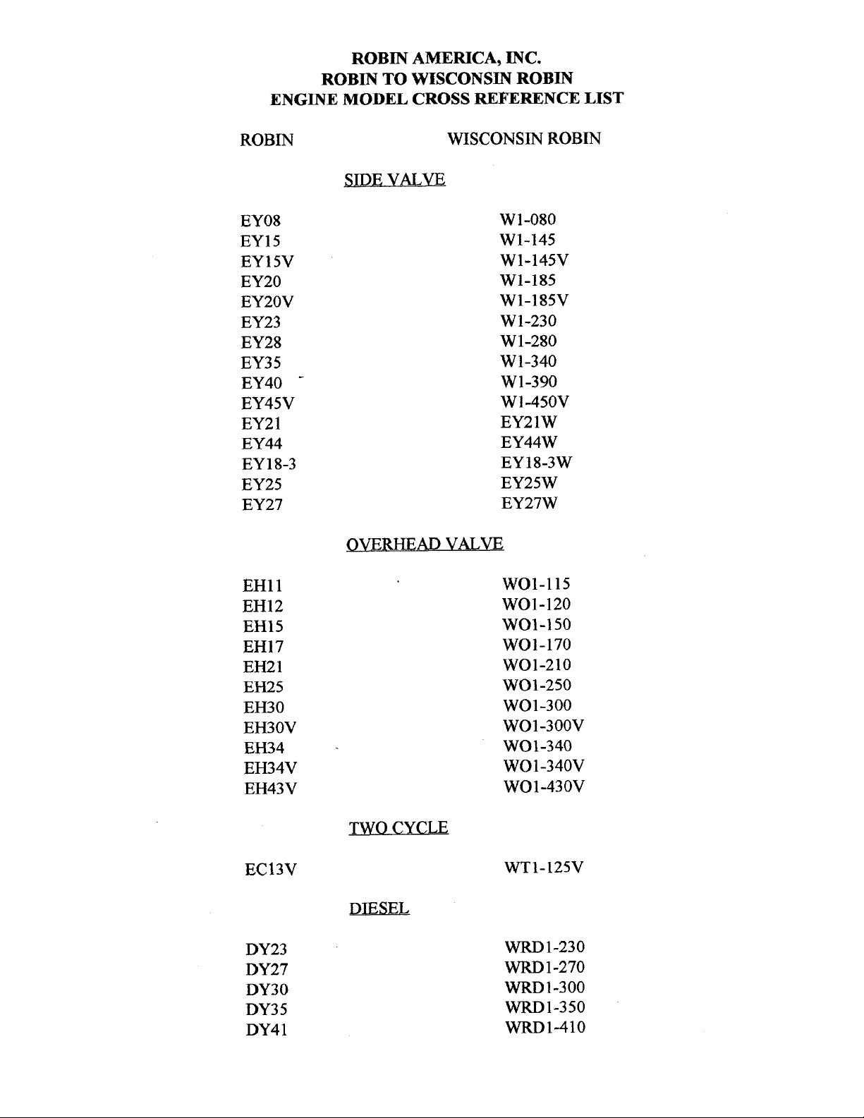
ROBIN
AMERICA, INC.
ROBIN
TO
WISCONSIN
ROBIN
ENGINE
MODEL
CROSS REFERENCE
LIST
ROBIN
EY08
EY15
EY 15V
EY20
EY2OV
EY23
EY28
EY3
5
EY40
-
EY45V
EY2
1
EY44
EY 18-3
EY25
EY27
EH11
EH12
EH15
EH17
EH21
EH25
EH30
EH30V
EH34
EH34V
EH43V
EC13V
DY23
DY27
DY30
DY3
5
DY4 1
WISCONSIN
ROBIN
SIDE
VALVE
W
1-080
W1-145
W1-145V
W1-185
W1-185V
W1-230
W 1-280
W
1-340
W 1-390
Wl-45OV
EY21W
EY44W
EY18-3W
EY25W
EY27W
OVERHEAD
VALVE
WO1-115
wo1-120
WO1-150
WO1-170
wo1-210
WOl-250
WO 1-300
WO1-300V
WO1-340
WO
1
-340V
WO 1-43 OV
TWO CYCLE
WT1-125V
DIESEL
WRD
1-230
WRD
1-270
-1-300
WRD1-350
WRD1-410
0
0
0
Page 3
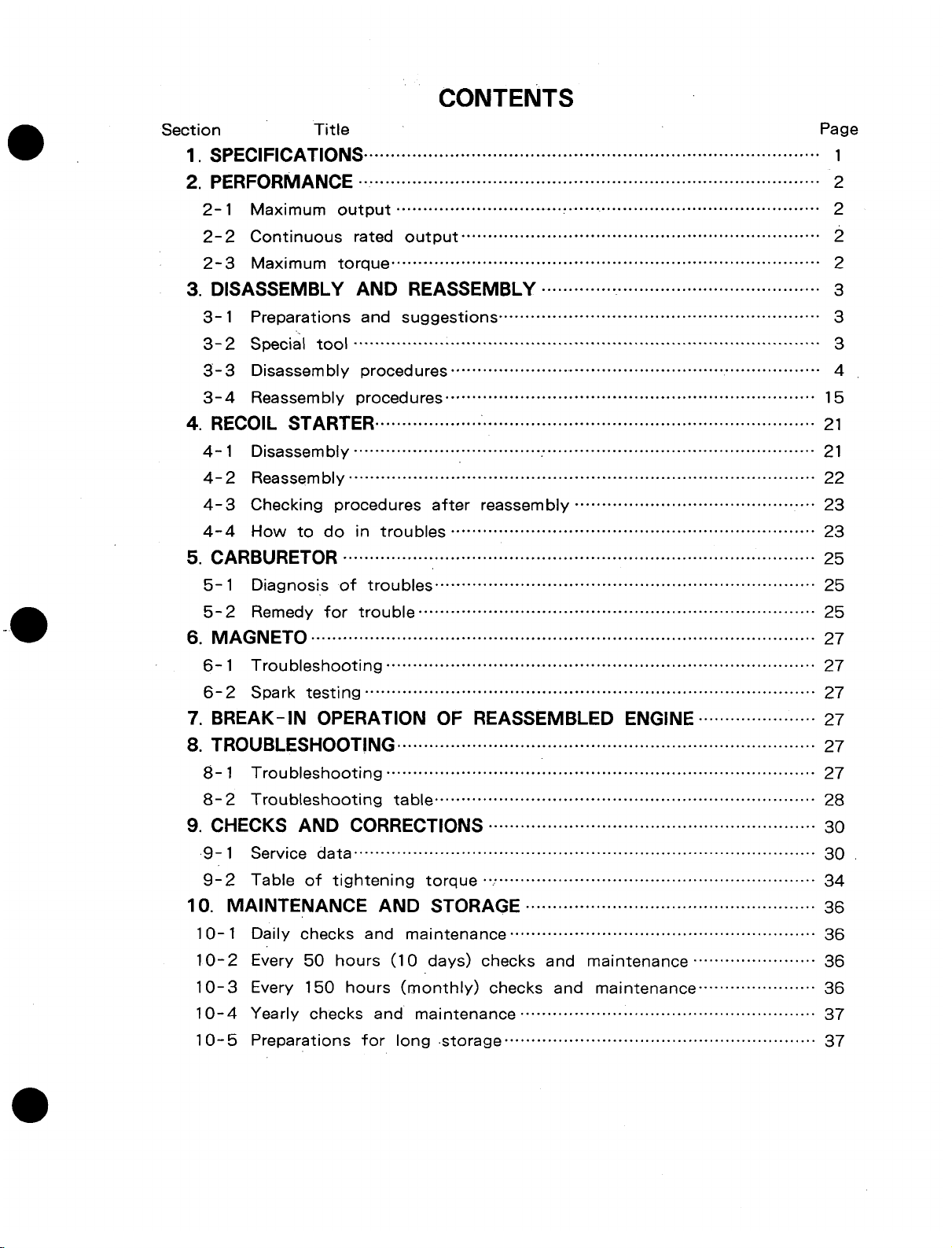
CONTENTS
Section
Title
Page
1.
SPECIFICATIONS" ""."O"""""•"O"O"C".O"""O"O"".O"""'"•""""""S""""""""""""."."""""".--"".--.-......C... 1
2. PERFORMANCE ..."...... ......".........""............ ......"......."".."............. ....."..C.". 2
2-1 Maximum output ...... C................................................"....".................. 2
2-2 Continuous rated output ...................................."............."................ 2
2-3 Maximum torque
................................................................................
2
3. DISASSEMBLY AND REASSEMBLY ......"."....................".."............"..... 3
3-1 Preparations and suggestions ...................................".....".................. 3
3-2 Special tool ............................................................... ........................ 3
3-3 Disassembly procedures .`..............".......................".. ".................."...... 4
3-4 Reassembly procedures .............."..............".. ".................................... 15
4. RECOIL STARTER ...."..... ...............................""................................... 21
4-1 Disassembly .."....."..............".............."... "............."............................. 21
4-2 Reassembly ."..............."............".................""".."............".................... 22
4-3 Checking procedures after reassembly ............................................. 23
4-4 How to do in troubles "........................"........................."................ 23
5. CARBURETOR ..........................".".............................. ....................... 25
5-1 Diagnosis of troubles ....................................................................... 25
5-2 Remedy for trouble ...................."................."................................... 25
6. MAGNETO .-.........."........-...."...."..............".. .........."""............."."............. 27
6-1 Troubleshooting ......"....."..........................................""....................... 27
6-2 Spark testing "".........................................."......................."... "".......... 27
7. BREAK-IN OPERATION OF REASSEMBLED ENGINE ... ................27
8. Troubleshooting ..................."".................• ........ ..................
27
8-1 Troubleshooting ............". "........................................."....................... 27
8-2 Troubleshooting table" ................"............"........................................ 28
9. CHECKS AND CORRECTIONS ..................... ...................... .... 30
9-1 Service data ...............".....................................................".........".".... 30
9-2 Table of tightening torque .... .................................."...................`.... 34
10. MAINTENANCE AND STORAGE ...................... .................. 36
10-1 Daily checks and maintenance ......".................................................. 36
10-2 Every 50 hours (10 days) checks and maintenance ....................... 36
10-3 Every 150 hours (monthly) checks and maintenance ...................... 36
10-4 Yearly checks and maintenance ....................................................... 37
10-5 Preparations for long .storage ......".. "........"....................................... 37
Page 4
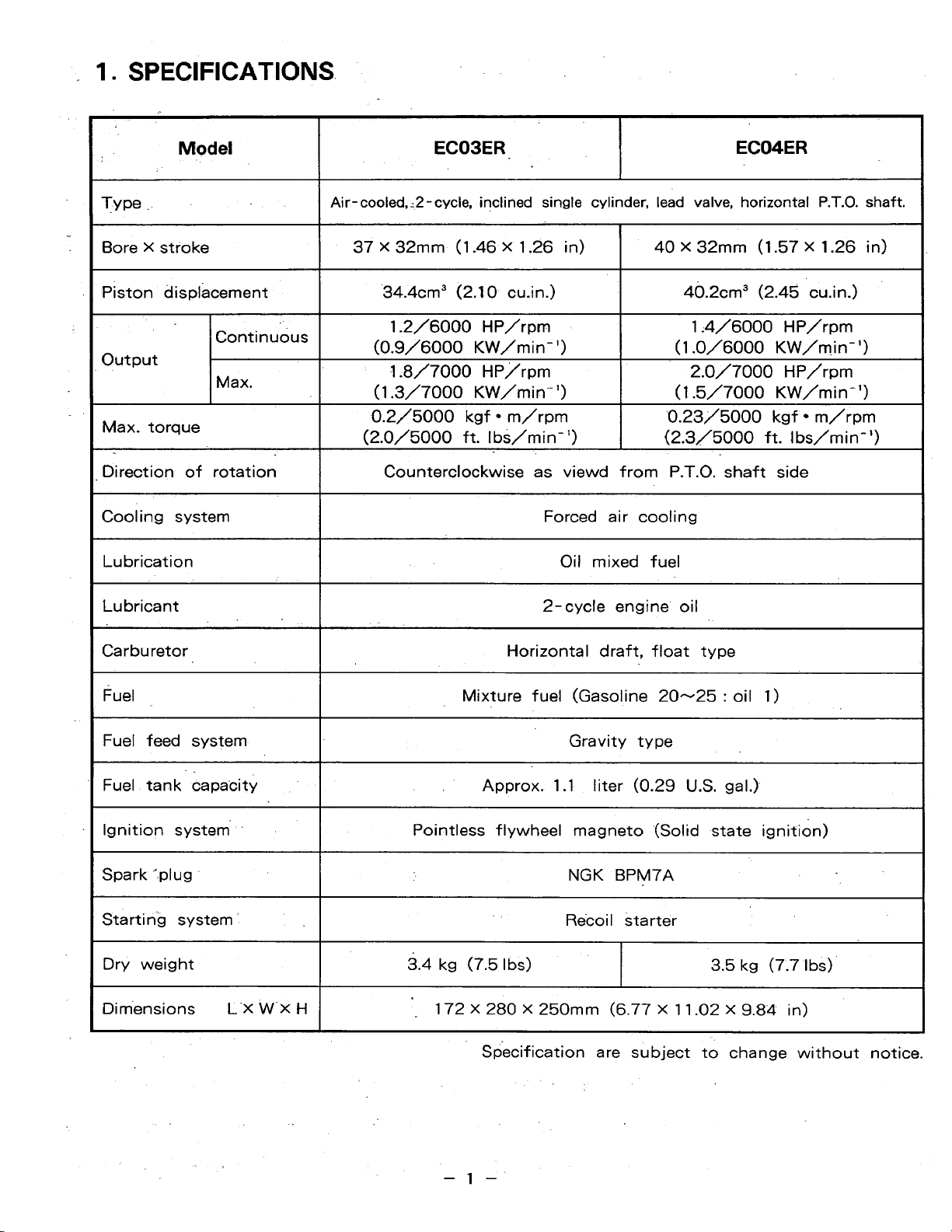
1.
SPECIFICATIONS.
I
I
Model
Type
:
Bore X stroke
Piston displacement
output
EC03ER
ECO4ER
1
Air-cooled,~2-cycle,
inclined
single
cylinder,
lead
valve,
horizontal
P.T.O.
shaft.
37
X
32mm
(1.46
X
1.26
in)
40.2cm3
(2.45
cu.in.)
34.4cm3
(2.1
0
cain.)
40
X
32mm (1.57
X
1.26
in)
1.2/6000
HP/rpm
1.4/6000
HP/rpm
(0.9/6000
KW/min")
(1.0/6000
KW/mi
n-
'1
.1.8/7000
HP/rpm
2.0/7000
HP/rpm
(1.3/7000
KW/min")
(1.5/7000
KW/min")
Max. torque
0.2/5000
kgf m/rpm
0.23/5000
kgf
m/rpm
I
(2.0/5000
ft.
Ibs/min")
I
(2.3/5000
ft.
Ibs/min")
Direction of rotation
I
Counterclockwise
as
viewd from P.T.O.'shaft side
Cooling system
I
Forced air cooling
Lubrication
I
Oil mixed fuel
Lubricant
Horizontal draft, float type Carburetor
2-cycle engine oil
Mixture fuel (Gasoline
20-25
:
oil
1)
Fuel
Fuel feed system
I-
Gravity type
Fuel tank capacity
Approx. 1.1 liter
(0.29
U.S.
gal.)
Ignition system
I
Pointless flywheel magneto (Solid state ignition)
Spark *.plug
NGK
BPM7A
Starting system
I
Recoi I starter
Dry weight
3.5
kg
(7.7
Ibs)
3.4
kg
(7.5
Ibs)
Dimensions
L-X
W-X
H
1
72 X 280
X
250mm (6.77
X
1
1.02
X
9.84 in)
a re subject
to
change without
-1-
Page 5
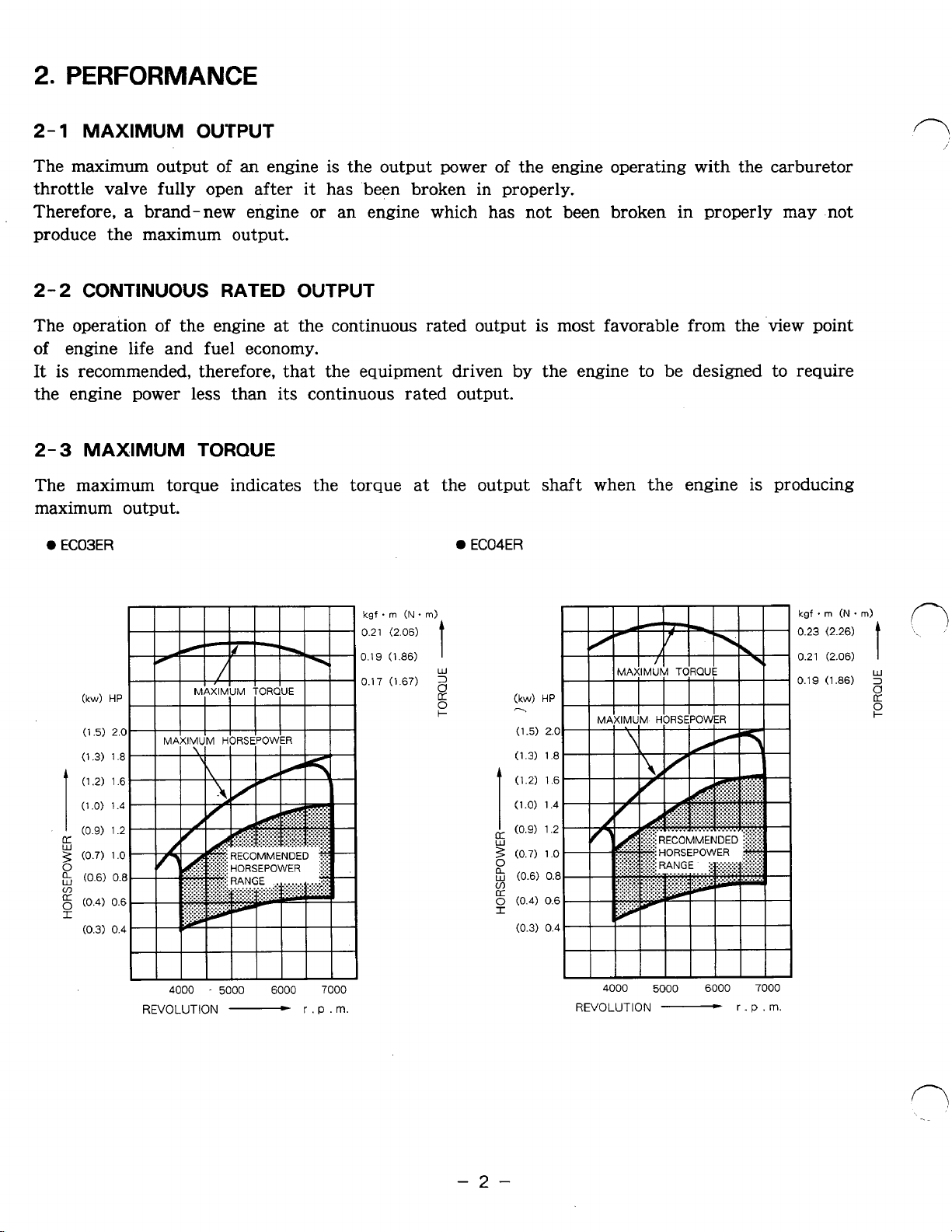
2.
PERFORMANCE
2-1
The maximum output
throttle valve fully open after
Therefore,
MAXIMUM OUTPUT
of
an
engine is the output power
a
brand-new engine
of
the engine operating with the carburetor
it
has .been broken in properly.
or
an engine which has not been broken in properly may not
produce the maximum output.
2-2
The operation of the engine at the continuous rated output
CONTINUOUS
RATED
OUTPUT
is
most favorable from the view point
of engine life and fuel economy.
It
is
recommended, therefore, that the equipment driven
by
the engine to
be
designed to require
the engine power less than its continuous rated output.
2-3
MAXIMUM
TORQUE
The maximum torque indicates the torque at the output shaft when the engine is producing
maximum output.
0
EC03ER
0
EC04ER
4000
.
REVOLUTION
5000
-
6000
kgf
*
m
(N
(2.26)
(2.06)
(1
36)
.
f-?
kgf
.
rn
(N
.
m)
0.21
(2.06)
0.19
(1.86)
0.17 (1.67)
7000
r
.
P .
m.
t
W
3
2
0
F
4000
REVOLUTION
5000
-
6000
r
.P
0.23
0.21
0.19
7000
.m.
-2-
Page 6
3.
DISASSEMBLY AND REASSEMBLY
3-
1
PREPARATIONS
AND
SUGGESTIONS
(1)
When disassembling an engine , memorize well the locations
of
individual
parts
so
that they
can be reassembled correctly.
If
you are uncertain of identifying some
parts,
it is suggested
that tags to be attached to them.
(2)
Have boxes ready to keep disassembled parts by group.
(3)
To
prevent missing and misplacing small parts such
as
bolts and nuts, etc., temporarily
assemble
as
much as possible in each group
or
set.
(4)
Carefully handle disassembled parts, and clean them with washing oil.
(5)
Use correct tools in correct way.
(6)
Standard tools required
for
disassembling and reassembling
:
a) Work table
b) Washing pan
c) Disassembling tools
d)
Washing oil (kerosene
or
light oil)
e) Emery paper, waste '.cloth
(7)
Before starting disassembly
of
the engine, drain fuel.
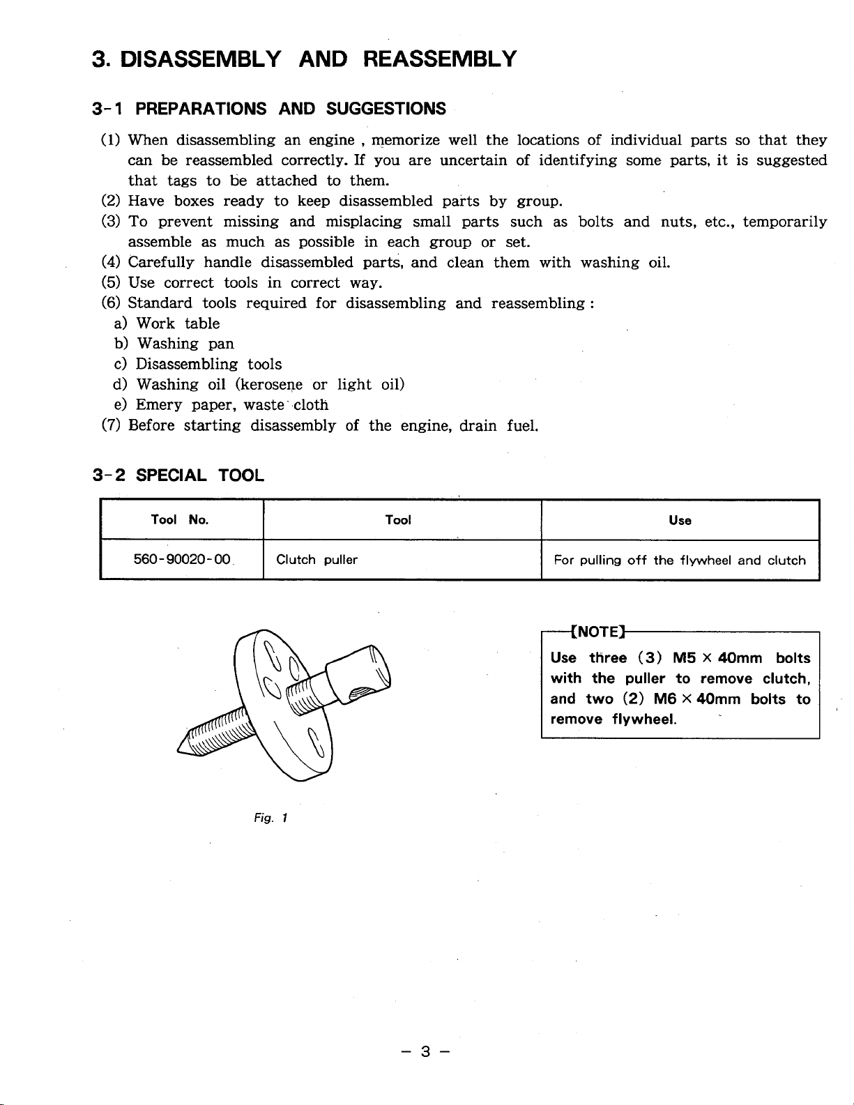
3-2
SPECIAL
TOOL
Tool
No.
Use
Tool
560
-
90020
-
00
For
pulling
off
the flywheel
and
clutch
Clutch puller
"--(NOTE]-
Use tKree
(3)
M5
X
40mm bolts
with the puller to remove clutch,
and
two
(2)
M6
X
4Omm bolts to
remove
flywheel.
Fig.
1
-3-
Page 7
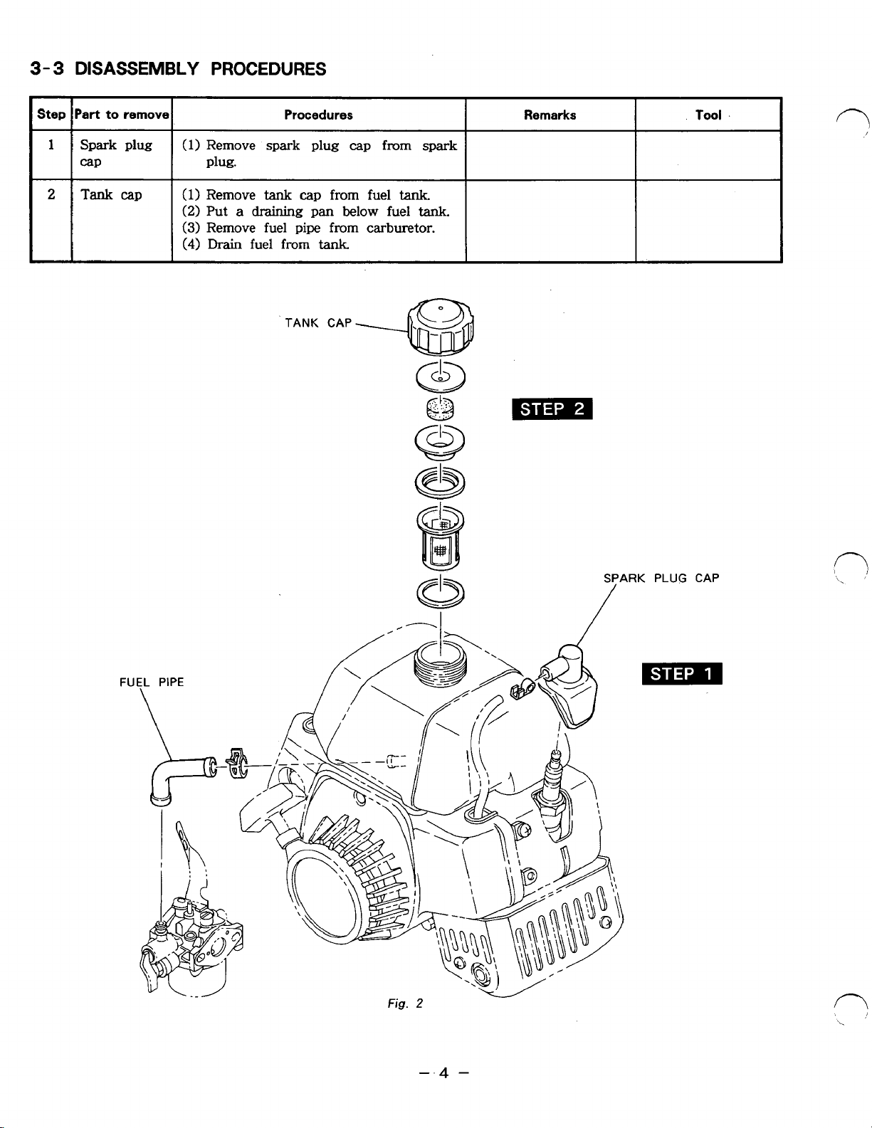
3-
3
Step
DISASSEMBLY
Part
to
remove
PROCEDURES
Procedures
Remarks
Tool
1
2
Spark plug
cap
Tank
cap
(1)
Remove spark plug cap from spark
plug.
(1)
Remove
(2)
Put
(3)
Remove fuel pipe from carburetor.
(4)
Drain
tank
a
draining
fuel from
cap
pan
tank.
TANK CAP
from
below fuel
~ ~ ~~ ~
fuel
tank.
tank.
*
~
SPARK PLUG CAP
Fig.
2
Page 8
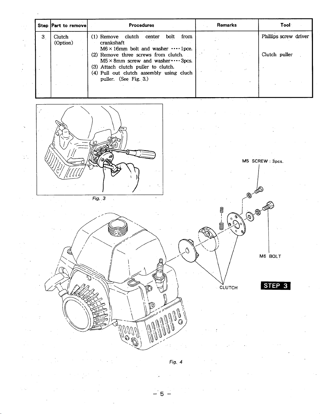
(Option)
Procedures
(1)
Remove clutch center bolt from
crankshaft
M6
x
16mm
bolt
and
washer
-
*-*
lpce.
(2)
Remove
ki-ee
screws
from clutch.
M5
x
8mm
screw
and
washer
*e*
Spa.
(3)
Attach clutch puller to clutch.
(4)
Pull
out clutch
assembly
using
cluch
,,
puller.
(See
Fig.
3.)
Fig.
.3
~mps
screw
driver
Clutch puller
M5
SCREW
:
3pcs.
Fig.
4
-5-
Page 9
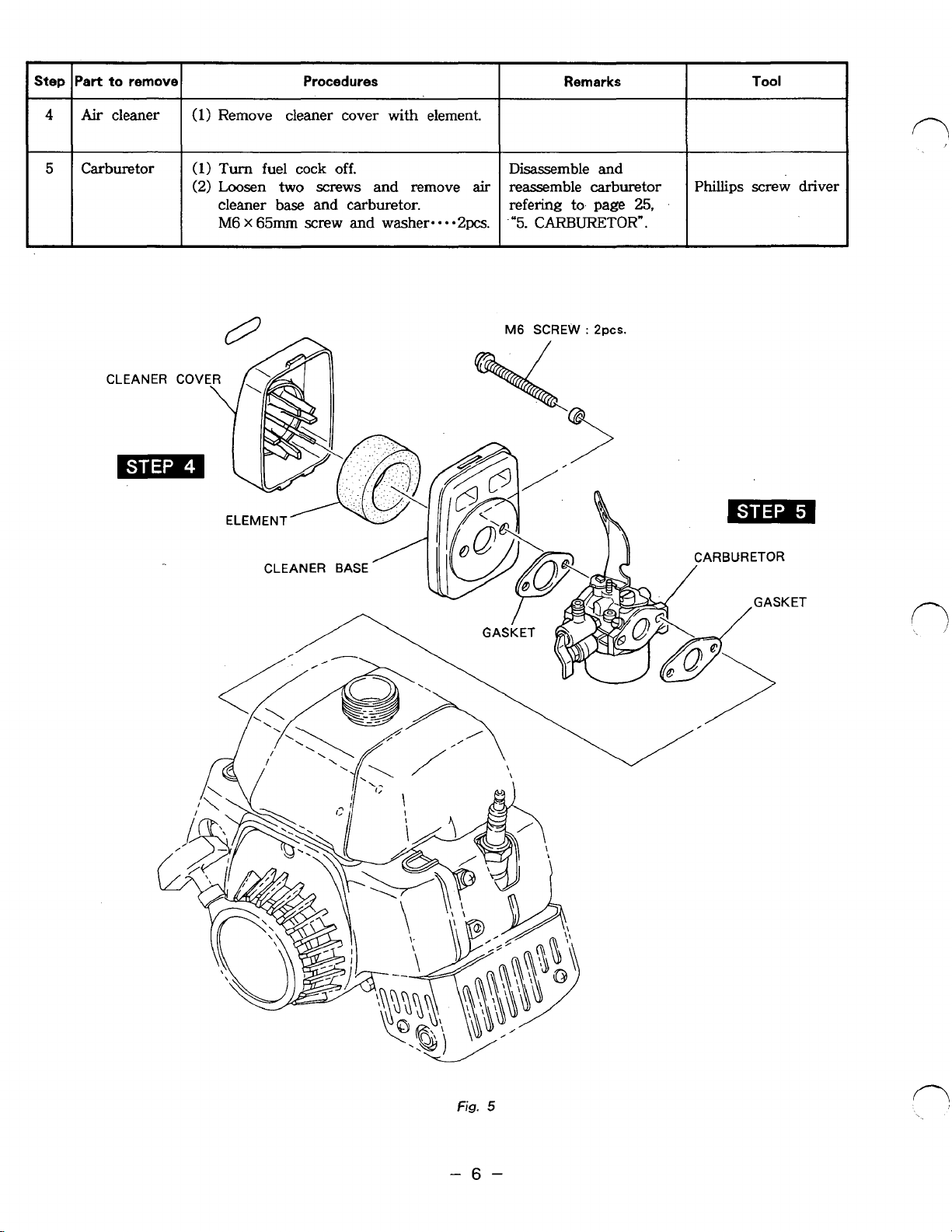
Step
4
Part
Air
to
remove
cleaner
Procedures
(1)
Remove cleaner cover with element.
Remarks
Tool
rl
5
Carburetor
(1)
Turn
(2)
Loosen
cleaner base
M6 x 65mm
fuel
cock
off.
two
screws
and
carburetor.
screw and washer....2
and
remove
Disassemble
air
reassemble carburetor
refering
pcs.
.'5.
CARBURETOR".
to.
and
page
25,
Phillips
screw driver
Page 10
-
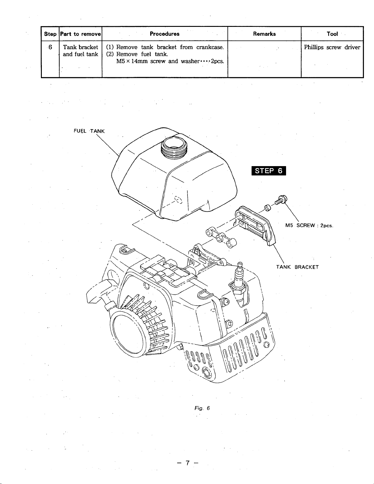
Step
6
-
Part
to
remove
Tank
bracket
and
fuel
tank
Procedures
I
I
Remarks
Tool
.
I
(1)
Remove
tank
bracket
from
crankcase.
(2)
Remove fuel
tank,
M5
x
14mm
screw
and
washer---.2pcs.
Phillips
screw driver
I
I
I
Fig.
6
-7-
Page 11
I
Step lPart
to
remove1 Procedures
I
Remarks
I
Tool
I
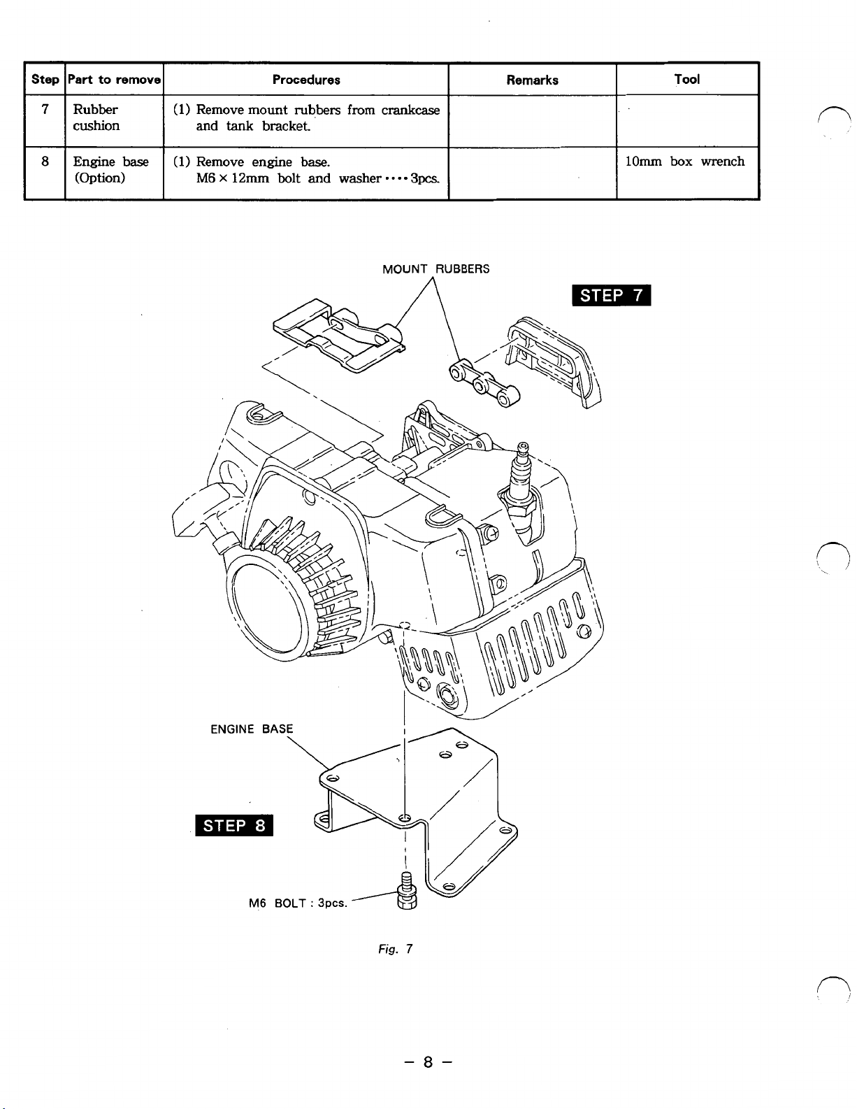
7
8
Rubber
cushion
(Option)
(1)
(1)
Remove
and
tank
Remove engine base. Engine base
M6
x
12mm
mount
bracket.
bolt
rubbers
and
from
washer
crank-
*
- -
-
3pcs.
MOUNT
RUBBERS
lOmm
box
fl
wrench
M6
BOLT
:
3pcs.
I
Fig.
7
-8-
Page 12
&=
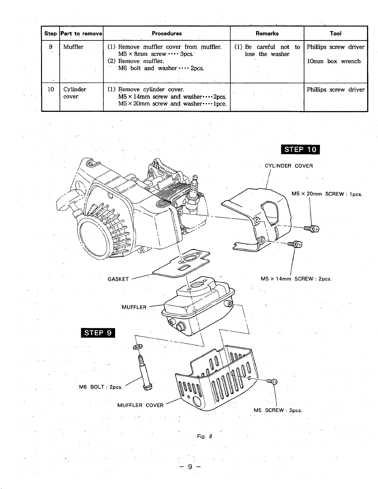
Step
Part
to
remove
*
cover
Procedures
(1)
Remove muffler cover from muffler.
(2) Remove muffler.
M5
x
8mm
screw
***a
3pc~:
'
M6
bolt and
washer
-
:
*-2pcs.
(1)
Remove cylinder cover.
M5
X
14mm
screw
and
waSher****2pcs..
M5
X
20mm screw
and
washer-.
0.
lpce.
Remarks
(1)
Be
careful
not
to
lose
the washer
Tool
Phillips
screw driver
lOmm
box
wrench
Phillips
scniw driver
.
..
Fig.
8
..
-9-
Page 13
Step
lpart to
remove1
Procedures
I
Remarks
I
Tool
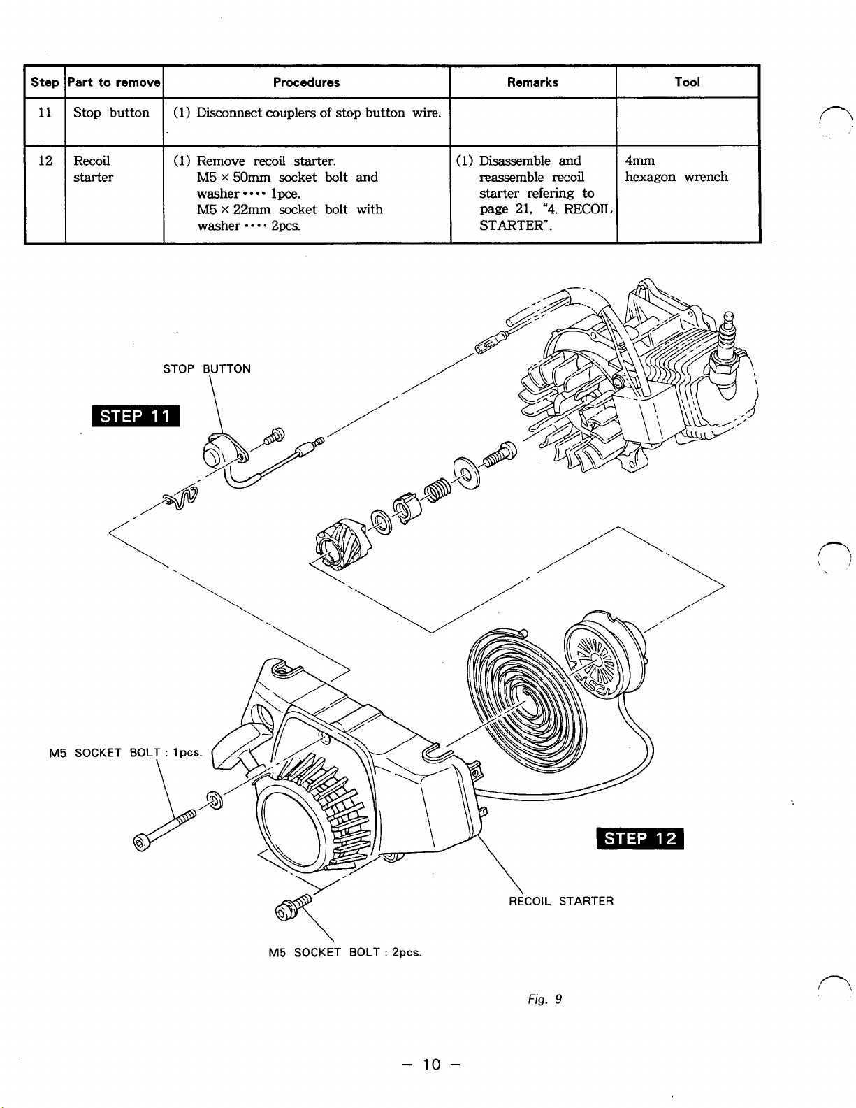
12
Stop button
Recoil
starter
(1)
Disconnect couplers
I.
(1
1
Remove
M5
X
50mm
washer
M5
X
22mm
washer
recoil
socket bolt
lpce.
socket bolt with
- - -
2pcs.
of
starter.
stop button
and
wire.
(1)
Disassemble
reassemble
starter
page 21,
STARTER".
and
recoil
refering
"4.
RECOIL
4mm
hexagon wrench
to
M5
SOCKET
BOLT
:
Ppcs.
-
10
Fig.
n
9
-
Page 14

-
Step
13
-
14
-
Part
to
remove
Procedures
lgnition
coil
Flywheel
magneto
(1)
Remove ignition
coil
from crankcase.
M5
x
2Omm
SCEW
**e*
2pcs.
(1)
Remove flywheel
bolt,
M6
X
16mm
bolt,
spring
washer and
washer
1
pce.
(2)
Set
clutch puller
to
flywheel.
(See
Fig.
10.1
Turn
center bolt clockwise to
pull
out
flywheeL
Remarks
I
Tool
1
Phillips screw driver
(1)
Be
careful
not
to
Clutch puller
lose washer
sd
spring
washer.
(2)
Flywheel
caq
easily
be
removed by
striking with a
hammer
the head
of
center
bolt
of
clutch puller.
Fig.
11
M5
SCREW
:
ZPCS.
.
IGNITION
COIL
-
11
-
Page 15

'art to rernova
Procedures
Remarks
Tool
Woodruff
key
Insulator
and lead
valve
M5
X
SCREW
22mm
:
2pcs.
I
(1)
Remove woodruff key
shaft.
(1)
Remove insulator and lead valve from
Crankcase.
M5
M5
X
20mm
x
22mm
(See
Fig.
12.)
screw and washerscrew and washer-
from
(NOTE1
Lead valve
Replace lead valve
if
necessaly.
$
is
unreplaceable.
~ ~~
WIRE BRACKET
in
completion from
crank
0.
-2pcs.
*a
-2pcs.
-
(1)
Use
a soft hammer
and aluminum stick.
(2)
Be careful not to
lose
key.
(3)
Be
careful not to
damage key and
crankshaft keyway.
Phillips
screw driver
M5
X
20mm
SCREW : 2pcs.
/
INSULATOR
v
PACKINGS
LEAD
VALVE
Fig.
12
Fig.
13
-
12
-
Page 16

..
.,
1-
..
step
Tool
Remarks
Procedures
Part
to
remove'
"1
9mm
(l).Remove spark
plug.
from cylinder.
'Spark plug
17'
plug
wrench
*.
r
..
.L
,
..
18
5mm
(1)
-Remove cylinder from
crankcase.
Cylinder
M6 X 18mm
socket
bolt
*-*a
4pcs.
hexagon wrench
..
..
...
.-
I
PACKING
I
CYLINDER
..
.
.
"_
-
13"
Page 17

Step
-
19
-
20
’art to remove
Crank-
Piston and
piston ring
Procedures
(1)
Disassemble front
M5
x
30mm
(1)
Remove two clips from
piston pin.
(2)
Remove piston pin from piston.
(3)
Remove piston from connecting rod.
(4)
Remove piston ring from piston.
[NOTE]
Connecting rod
Replace connecting rod and crankshaft
in assembly form
PISTON RING
and
socket bolt
is
unreplaceable.
if
necessaly.
mar
both
crankcases.
e
PISTON
4pcs.
ends
Remarks
(1)
Be
careful
damage
of
(1)
Be
careful not to
lose
clips.
(2)
Be
careful
give damage to the
piston
connecting
(3)
Be
careful not to
break piston rings
by spreading, too
much
them.
oil
and
or
not to
sed
not to
rod
twisting
4mm.
hexagon wrench
Long nose pliers
Tool
f7
PISTON
NEEDLE BEARING
CRANKSHAFT
PIN
I
GASKET
OIL
SEAL
\
M5
CRANKCASE (REAR)
SOCKET
BOLT
:
4pcs.
\
OIL
SEAL
CRANKCASE(FRONT1
Fig.
15
-
14
-
Page 18

3-
4
REASSEMBLY PROCEDURES
0
PRECAUTIONS FOR REASSEMBLY
(1)
Clean parts thoroughly before reassembly.
(2)
Scrape off all carbon deposits from cylinder head, piston top
and
piston ring grooves.
(3)
Check lips
of
oil seals. Replace oil seal if I a lip is damaged.
(4)
Replace all gaskets with new ones.
(6)
Torque bolts and. nuts
to
specification refering. to page
34,
“9-2
TABLE
OF
TIGHTENING
(7)
Apply oil to rotating and sliding
parts.
(8)
Check and adjust clearances
and
end plays where specified in this manual.
Pay most attention to cleanliness of piston, cylinder, crankshaft, connecting rod and bearings.
Apply oil to lips before reassembly.
(5)
Replace keys, pins, bolts, nuts, etc., if necessary.
TORQUE”.
3-4-1
PISTON
AND
PISTON RING
(1)
If piston ring expander is unavailable, install piston rings by placing the open ends over the
top land of piston and. spreading the ring ends only far enough
to
slip them into the correct
ring grooves.
-[NOTES]
1.
Pay attention not to break piston ring
by
twisting.
2. Top
ring and second ring are common parts.
3.
Set piston ring ends to location pin as shown in Fig.
16.
Fig.
16
!
TOP
RING
AND
SECOND
RING
TAPER
-
15
-
Page 19

(2)
Install needle bearing to small end of
connecting rod.
(3)
Assemble piston and connecting
piston pin and clips. (See page
14,
rod
Fig.
with
15.)
Set the
flywheel
3-4-2
(1)
(2)
(3)
(4)
(5)
"M"
mark stamped on piston top to
side
of
piston.
CRANKCASE
Insert magneto end of crankshaft into front crankcase bearing.
Put gasket on the fitting surfaces
Insert
Tighten
M5
Insert key to crankshaft.
FTO
end of crankshaft into rear crankcase bearing. (See Fig.
four
(4)
bolts evenly to join rear crankcase to front crankcase.
X
30mm socket bolt
TIGHTENING TORQUE
60
-
80
kgf
590
-
780
N
55
-
65
IN-LB
*cm
crn
0.
4pcs.
of
crankcase. (Use new gasket.)
Fig.
17
17.)
n
,
i
3-4-3
(1)
3-4-4
(1) Put cylinder gasket on the fitting surface of crankcase. (Use new gasket.)
(2) Insert piston to cylinder.
(3)
ENGINE
Install engine base to crankcase.
Tighten three
M6
x
12mm bolt and washer
TIGHTENING TORQUE
590
55
I
CYLINDER
Put cylinder
M6
X
18mm socket bolt
1080
-
-
-
BASE
80
780
65
to
1270
(OPTION)
(3)
bolts evenly
kgf
*cm
N
-
cm
IN-LB
crankcase.
N*cm
-0
-0
*e*
4pcs.
to
join engine base to crankcase.
3pcs.
-
16
-
Page 20

3-4-5
CYLINDER COVER
(1) Install cylinder cover to cylinder.
M5
X
14mm screw and washer 2pcs.
M5 X 20mm
screw and washer
* * *
lpce.
I
.TIGHTENING
TORQUE
I
30
-
40
kgf
cm
295 - 390
N
cm
30
-
35
IN-LB
3-4-6
LEAD VALVE AND INSULATOR
(1) Install gasket lead valve, with gasket, insulator and wire bracket
to
crankc
M5
X
20mm screw and washer 2pcs.
M5
X
22mm screw and washer 2pcs.
395 - 490
N
cm
ase.
r
Apply
sealant
(THREE BOND
#
1360)
to
screws.
I
I
3-4-7
CARBURETOR AND
AIR
CLEANER
(1)
Install carburetor gasket and carburetor, then mount air cleaner base.
(2)
Set cleaner element
to
cleaner cover.
(3)
Set cleaner cover to cleaner base. (See page 6, Fig.
5.)
M6
X
65mm screw and washer 2pcs.
TIGHTENING
TORQUE
40
-
50
kgf
cm
395
-
490
N
cm
35
-
40
IN-LB
3-4-8
MAGNETO
(C.D.I.)
(1)
Install woodruff key
to
crankshaft.
(2)
Install flywheel
to
crankshaft.
M6 X 16mm bolt, spring washer and washer 1 pce.
I
TIGHTENING
TORQUE
I
110
-
130
kgf
*cm
1080
-
1270
N-cm
95
-
110
IN-LB
I
I
(3)
Install ignition coil
to
crankcase.
M5
X
20mm screw 2pcs.
-
17
-
Page 21

(4)
Adjusting air gap between ignition coil
and flywheel. (See Fig.
18.)
I
I
(5)
Tighten ignition coil to crankcase.
I
TIGHTENING TORQUE
Before installing flywheel, wipe out oil from crankshaft and the tapered center hole of flywheel.
r
3-4-9
(1)
Install
0.0079
40
-
395
-
35
-
SPARK
spark
AIR
GAP
-
0.0157
50
kgf
*cm
490 N
40
PLUG
cm
IN-LB
plug to cylinder.
IN
1
I
(NGK
BPM7A
or
the equivalent)
Fig.
18
n
/
I
TIGHTENING TORQUE
1470
130
3-
4-
10
CLUTCH (OPTION)
(1)
Assemble clutch.
M5
X
8mm
30
295
30
(2)
Install clutch
M6 X 16mm
I
TIGHTENING TORQUE
100
-
-
-
-
-
-
2055 N
screw
390
210
kgf
cm
180 IN-LB
and
40
kgf
N
cm
35
IN-LB
to
crankshaft.
bolt
and washer
120
kgf
*cm
crn
washer
cm
I
**
**a*
3pcs.
lpce.
980
90
-
-
1175
100
N
cm
IN-LB
-
18
-
Page 22

3-4-1 1
FUEL TANK
(1)
Set tank cap to fuel tank. (See page 4,
Fig.
2.)
(2) Install mount rubbers to crankcase.
(4)
Put fuel tank
on
crankcase.
I
(3)
Connect fuel pipe to carburetor.
3-4-12
TANK
BRACKET
(1) Attach tank bracket to crankcase.
M5
X
14mm screw and washer
-0
2pcs.
I
TIGHTENING TORQUE
I
40
-
50
kgf
cm
395 - 490
N
cm
35
-
I
40
IN-LB
-
3-
4-
13
MUFFLER
.(
1)
Install muffler to crankcase using muffler gasket. (See Fig.
19.)
-.
M6
muffler bolt and washer
0.
2pcs.
I
TIGHTENING TORQUE
I
00°
CYLINDER
SIDE
'
-
*MUFFLER
SIDE
Fig.
19
[NOTES]
Use new muffler
gasket.
Apply
sealant
(THREE
BOND
#
.1360)
to
muffler bolt and washer.
-
19
-
Page 23

3-4-
14
MUFFLER COVER
(1)
Install muffler cover
M5 X 8mm
I
TIGHTENING
35
345
-
-
screw
440
TORQUE
45
kgf-cm
N-cm
to
3pcs.
I
muffler.
30 - 35
I
3-4-15
(1)
(2)
3-4-
(1)
STOP BUTTON
Connect wire from ignition coil to stop
button.
Check earth spring to protrude from the
mounting surface
(See Fig.
16
Install recoil starter to crankcase.
M5
X
M5
X
20.)
RECOIL STARTER
22mm socket bolt with washer 2pcs.
50mm socket bolt and washer
IN-LB
of
I
recoil starter.
Fig.
20
0.
-0
lpce.
I
'
TIGHTENING TORQUE
35
-
55
345 - 535
30
-
45
3-4-17
(1)
SPARK PLUG CAP
Connect spark plug cap
kgf
*cm
N-cm
IN-LB
I
to
spark plug.
-
20
-
Page 24

4.
RECOIL
STARTER
When repairing recoil starter, disassemble and reassemble in the following procedures.
Tools
:
Socket. wrench, Needle nose pliers, Screw driver.
4-
1
DISASSEMBLY
(1)
Remove recoil starter from engine.
(2)
Pull starting knob to pull out starter rope.
(See
Fig. 21.)
Fig.
21
(3)
Hold reel with thumb and pull starter rope
inside case. (See Fig. 22.)
(4)
Rewind
rope
clockwise until rotation stops
by holding starter rope using the notch on
the reel.
When rewinding the rope, control rotation by
pressing the
reel
with thumb.
Fig.
22
Remove parts in the following
1.
Screw
2:
Washer
3.
Friction spring
4.
Ratchet guide
5.
Thrust washer
6.
Ratchet
Fig.
23
-
21
-
Page 25

(6)
Remove reel from starter case as shown in
24.
Fig.
Take out .reel slowly turning it lightly
toward left and right
to
remove spring from
hook.
-
[NOTE]
Do
not remove reel quickly or the spring may
escape from starter case.
If
the spring escapes, put
as
instructed in page
TROUBLES.
(7)
Untie starter rope from the
23,
it
in the starter case
4-4
HOW
TO
DO'
knob
IN
and
remove.
4-
2
REASSEMBLY
(1) Check that spring is securely set in the reel.
(2)
Adjust the position
spring
so
it catches hook
of
inner end
of
the reel securely.
of
the
Fig.
n
24
[NOTE]
The shape
adjusted with plier
(3)
Prior
of
starter spring inner end can be
if
necessary.
to installing reel in starter case, wind
starter rope in reel for 2.5 turns in
arrowhead direction as shown in Fig. 25.
(4)
Then let rope out
reel. Line up reel
spring
as
shown in Fig.
of
reel from notch
hook
with inner end of
26
and install reel
in starter case.
(5)
Hold starter rope, as
reel
3
times in arrowhead direction.
(6)
Firmly press the reel not
shown
Fig. 27 and turn
to
allow reverse
turn.
on
I
f-7
\
,'
Fig.
25
I
OUTER END
OF
SPRING
INNER
END OF
-
22
-
SPRING
Fig.
26
f-7
Page 26

(7)
Reassemble parts in reverse order
of
disassembly. (See Fig. 23.)
Screw
*****
1
pce.
TIGHTENING
TORQUE
295
-
390
kgf
cm
30
-
40
N*cm
30
-
35
IN-LB
0
This ,is the end of the disassembly and
reassembly procedures.
Test the reassembled recoil starter by the
following checking procedures in the next
section.
Fig.
27
4-
3
CHECKING PROCEDURES AFTER REASSEMBLY
(1)
Pull starting knob
2
or
3
times, and pull out starter rope a little.
a) If starting knob
is
felt heavy to pull
or
cannot be pulled, check whether all the
parts
are
b)
If ratchet does not function, check whether spring is hooked properly.
a)
If
starter rope remains left in reel or starter rope does not return at all, immoderate strain
is imposed on the
spring.
So
rewind starter rope 1 or 2 times as per instruction in
Fig.
22.
b)
If'
return power of
starter
rope is weak
or
starter rope cannot be fully rewind, inject a few
drops
of
mobile oil to the frictional portions.
If
it does not recover yet, wind the rope 1
or
2
times.
(In
this
case, refer to the instructions explained
in
paragraph a) above and confirm whether
or not immoderate strain is imposed on spring.)
c)
If a sound is heard that spring is falling off, and starter rope does not return, reassemble
once again from the biginning.
installed correctly.
(2) Pull starting knob, and pull out starter rope all the way long.
(3)
Push the washer
a)
If
washer
is
loose, retighten the bolts.
4-4
HOW
TO
DO
IN
TROUBLES
(1)
IN
CASE THE
SPRING
JUMPS
OUT
AT DISASSEMBLING.
Remove starter knob
from
rope.
0
Remove reel from starter case.
0
Hook outer end of spring
to
the reel. (See Fig.
26.)
0
Wind spring into the reel.
0
After winding
3
or
4
turns, tape spring
to
the reel
to
prevent the spring from jumping
out.
r
Prass outer end
of
spring
by
a
thumb
or
spiral spring jumps out
from
reel.
-
23
-
Page 27

(2)
Wind
0
Hook
Remove
IN
spring completely.
inner end
tape
CASE
OF
Lubricate the rotating
oil at the time
of
spring to reel.
from
reel.
LUBRICATING
parts,
of
disassembly
frictional
or
at the end
parts
Fig.
28
and spring with heat resistant grease,
of
season
for
use.
or
mobile
-
24
-
Page 28

5.
CARBURETOR
-
b
.
-.
. .-
5-1
-
DIAGNOSIS OF TROUBLES
0
Engine does not. start.
,.
Carburetor needle valve- is held open by dirt
or
gum.
(See remedy
1)
'
.
Pilot, jet is partially clogged. (See' remedy.
2)
..
..
.
..
..
@
Unstable engine operation.
,.
Carburetor needle valve is held open by dirt
or
gum. (See remedy
1.)
Main jet is partially clogged. (See remedy
3)
Pilot
jet
is partially clogged. (See remedy
2)
Main jet is partially clogged. (See remedy
3)
.
-
,
-
@
Carburetor floods.
..
Carburetor needle valve is held open by dirt or
gum:
(See remedy-
1)-
..
@
Idling speed is high or slow.
..
..
Adjust. the slow speed screw. (See remedy
4)
"
@
Engine exhausts white smoke.
5-2
REMEDY
FOR
TROUBLES
L"
..
Remedy
1
(2)
Remove float chamber from body.
"
(1)
Remove' fuel strainer' from body.'
:
(3)
If
needle valve. is . held open, disassemble
float and clean needle valve and fuel line
;in kerosene and blow the remai.nings with
compressed air. (See Fig.
29.)
'
(4)
Clean fuel strainer in kerosene.
(5)
Attach needle valve and float
to
body.
(6)
Attach float chamber
to
body.
I
TIGHTENING
TORQUE
I
70
kgf
cm
685
N'..'
cm
..
(7)
Attach ,fuel strainer
to.
body.
FUEL
STRAINER
4
T
..
Fig.
29
TIGHTENING TORQUE
35
kgf
cm
.
.
..
.I
345
N
cm
-
30
LB
':+
..
..
,_
..
.
I,.
.
.
.
..
.I
..
,-
Page 29

Rznnsdy
(1)
Remove pilot screw from body.
(2)
Clean pilot screw
2
and
vent of screw by
blowing compressed air.
(3)
Clean pilot vent
in
kerosene and blow
compressed air. (See Fig. 30.)
(4)
Reset pilot screw at 1% turns from full
closed position.
Remedy
(1)
Remove float chamber from body.
(2)
Remove main jet from body.
(3)
Clean
(4)
Clean main nozzle in kerosene and blow
3
main
jet
in
kerosene.
compressed air.
(5)
Clean main air vent in kerosene and blow
compressed air. (See Fig.
(6)
Attach float chamber to body.
TIGHTENING TORQUE
70
kgf
crn
685
N
cm
60
IN-LB
Remedy
(1)
Start the engine.
(2)
Check r.p.m.
(3)
Ajust the slow speed
4
by
tachometer.
(2800min”) by turning slow
at
30.)
2800
r.p.m.
set
screw.
(See Fig. 31.)
I
PiLoT
VENT
Fig.
I
30
[NOTE]
Slow
Check the specification
slow
(4)
speed is different
speed.
Stop the engine.
by
,each specification.
of
machinery and ajust
Fig.
31
-
26
-
Page 30

6.
MAGNETO
6-
1
MAGNETO TROUBLESHOOTING
When engine does not
start
or
starts
with difficulty,
or
when its operation is unstable, the following
.tests will clarify if they are caused by a defect in magneto.
(1)
Check ignition cable for possible corrosion, broken, worn insulation or loose connection.
(2)
Check sparks as described in the following - section.
(3)
If
no spark flys, replace ignition coil.
..
6-2
SPARK
TESTING
Remove spark plug from cylinder head and place it on cylinder, with the ignition cable
connected to it.
Crank
the engine several times by recoil starter and observe sparks at the spark gap of spark
plug.
If
spark
is
strong, the ignition system .can be eliminated as the source
of
trouble.
If
the spark
is
weak
or
there is no spark. at all, repeat the checks. according to the trouble-
shooting chart "Ignition system problems caused by" (Refer to section
"
8
TROUBLE
-
SHOOTING").
BREAK-
IN
OPERATION
OF
REASSEMBLED ENGINE
overhauled engine must be operated carefully
to
break-in the parts.
A
thorough break-in is indispensable particularly when the cylinder, piston
or
piston ring are
replaced with new ones.
.For
break-in of' overhauled engines; use mixture fuel
of
gasoline
20
:
1
part
oil for the first
ten
(1
0)
hours
of
operation.
8.
TROUBLESHOOTING
8-
1
TROUBLESHOOTING
The following three conditions must be fulfilled for satisfactory engine starting.
1.
The cylinder filled with a proper fuel- air mixture.
2.
Good compression in the cylinder.
3.
Good spark, properly timed, to ignite the mixture.
The engine cannot be started unless these three coditions are met. There are also other factors
which make engine start difficult, such as
a
heavy load initially applied
to
the engine, and
a high back pressure due
to
a long exhaust pipe.
The most common causes of engine troubles are given in
the
tables in the following pages.
..
.
-
27
-
Page 31

8- 2 TROUBLESHOOTING
TABLE
POSSIBLE
CAUSES
\
Fuel tank empty
Improper or contaminated fuel
Loose fittings or defective fuel
Carburetor not choked enough (cold
engine)
External fuel leaks
Clogged
Vapor lock (Fuel evaporating
lines due to excessive heat around
engine)
Carburetor needle valve held open
dirt
Incorrect mixtuer ratio of gasoline and
two cycle oil
Air
plugged or clogged
High speed jet
clogged
fuel
filters or
or gum.
vent
hole of the fuel tank cap is
in
dirty
carburetor partially
lines
in
lines
fuel
0
by
Clogged air cleaner
Faulty carburetor
Loose or corroded electrical
connections
Faulty ignition coil
Ignition wires disconnected or broken
plug
Spark
cable wet or broken
0
0
0
0
f
-
28
-
Page 32

SYMPTOMS
'
;
P
b
"$
.cn
4-
0
0
4-
4-
0
c
-
-
.-
3r
ma
a,
POSSIBLE
CAUSES
.-
C.t;
15$
Spark
plug
wet
or
dirty
Spark plug gap incorrect
I
'0
Spark timing incorrect
-I
~~~~ ~~~ ~
Incorrect air gap of ignition coil
Lack of lubrication 'on moving parts
due to long storage
Loose or broken spark plug
0
Worn
piston
or
piston ring
0
Scored
or
worn cylinder walls
0
Carbon
or
lead deposits
in
cylinder
or
on piston
Worn
or
damaged piston
-pin
or
needle
bearing
Worn
or
damaged crankshaft bearing
Low
cranking speed
Engine overloaded
Heavy load at low engine speed
I.
Cooling air restricted by dirt
or
debris
I
Engine operated
in
confined space where
cooling air
is
confinually recirculated
Clogged exhaust
Engine cold
TO.
USE
CHART
. ..
1.
Find problem under problem listing.
.2.
Foilow down column to a black dot.
..
'.
,
,"
1-
-.
:$.
3.
Refer to left
of
dot
for
probable cause.
4.
If first probable cause does not solve problem,
go
to next black dot.
-
29
-
Page 33

9.
CHECKS
AND
CORRECTIONS
After disassembling and cleaning engine, check and repair, if necessary, according to the correction
table. The correction table applies whenever engines are repaired.
It
is important
Correct maintenance
The meanings
(1
CORRECTION
Repair, adjustment
(2)
CORRECTION
The limit on wear, damage
engine performance cannot be expected without repairing such
(3)
USE
LIMIT
The limit beyond which parts can no longer be used in respect
(4)
STANDARD
for
the servicemen
is
recommended by observing the correction standards specified.
of
the terms used in correction table are as follows
or
replacement of any engine
LIMIT
DIMENSIONS
to
be familiar with contents of this table.
parts.
or
functional deterioration of engine
:
parts
parts.
of
performance
beyond which normal
or
strength.
The design dimensions of new parts minus tolerance.
(5)
CORRECTION TOLERANCE
of
Tolerance on. dimensions
9-
1
SERVICE
DATA
engine parts refinished
or
adjusted.
Unit : mm
(in)
f-7
/J
I
CYLINDER
0
Inside dia. (average)
PISTON
Piston
(thrust direction)
Ring groove width
(maximum)
size.
ITEM
TOP
TOP
,ECOSER
37.000-37.01 6
36.95-36.98
1.63- 1.65
(0.0642-0.0650)
I
37.035
(1
;4581) (1.4567-1.4573)
1.73
)
40.01 4-40.030
(1.5754-1.5760)
39.95-39.98 36.93
(1.5728- 1.5740) (1.4539) (1.4547- 1.4559)
1.63- 1.65
(0.0642-0.0650) (0.0681
EC04ER
Limit
40.049
(1.5767)
39.93
(1.5720)
1.73
(0.068
1
)
2nd
mt
2nd
1.60- 1.62
(0.0630-0.0638)
1.60- 1.62 1.73
(0.0681
-
30
-
)
(0.0630-0.0638)
1.73
(0.068
1
)
Page 34

Unit
:
rnm
(in)
ITEM
Piston
pin
hole
(maximum)
n
0
Clearance between piston
and cylinder
20mm (0.7874)
-
,
Ring groove side
clearance
0
Clearance between piston
pin
hole and piston
pin
E3
::a::*
...
:..
.*:,
.
.....
TOD
2nd
ECOSER
STD
9.99
1 - 1
0.002
0.3933-0.3938)
0.020-0.066
0.0008-0.0026)
0.07-0.1
1
0.0028-0.0043)
0.04-0.08
0.001
6-0.0031
)
-
0.009-0.008
-
0.0004-0.0003:
Limit
10.03
(0.3949)
0.1
05
(0.0041
0.1 5
(0.0059)
0.15
(0.0059)
i
0.044
(0.001
7)
EC04ER
~~
STD
9.99
1
-
1
0.002
(0.3933-0.3938)
0.034-0.080
(0.001 3-0.0031
0.07-0.1
1
(0.0028-0.0043)
0.04-0.08
(0.001 6-0.0031
-
0.009-0.008
(-
0.0004-0.00031
Limit
10.03
(0.3949)
0.1 19
(0.0047)
0.1 5
(0.0059)
0.1 5
(0.0059)
0.044
(0.001
7)
-
31
-
Page 35

Unit : mm (in)
ITEM
Piston ring end
Piston ring
(minimum)
0
Piston pin outside dia.
(maximum)
gap
width
TOP
2nd
I
TOP
2nd
ECOSER
STD
I
0.1
-0.3 0.8
(0.0039-0.01
0.1 -0.3
(0.0039-0.01 18)
1.54- 1 -56
(0.0606-0.061 4)
1.54- 1 56
(0.0606-0.061 4)
Limit
I
1
8) (0.031 5)
’
(0.031 5)
(0.0591
0.8
1.5
(0.0039-0.01 18)
(0.0039-0.01 18)
<0.0606-0.0614)
(0.0606-0.061 4)
)
EC04ER
STD
0.1
-0.3
0.1 -0.3
1.54-1 -56
1.54- 1.56
Limit
1
.o
(0.0394)
1
.o
(0.0394)
1.5
(0.059
1.5
(0.0591
1
1
CONNECTING
Big
end
Small end inside dia.
ROD
side
ITEM
clearance
9.994- 1 0.000
(0.3935-0.3937)
9.986
(0.3931
)
STD
0-0.’023
(0-0.0009>
9.994-
(0.3935-0.3937)
EC03ER,
1
O.Ob0
EC04ER
9.986
(0.3931
Unit : mm, (in)
Limit
0.7
(0.0276)
)
14.000- 1 4.01
(0.551 2-0.551
-
32
-
1
6)
14.026
(0.5522)
Page 36

Unit
:
mm
(in)
ITEM
XANK
SHAFT
D
Journal dia.
_.
uu
Side clearance between crankcase and crankshaft
(at assembled)
Gasket has a thickness
of
0.4mm (0.0157
in)
(when tighting)
0
Runout of shaft
18.5mm
CARBURETOR
Pilot screw
Spark plug type
Spark timing
Air gap
Spark plug gap
ECOBER
STD
1
4.994- 1 5.002
(0.5903-0.5906)
0.48
(0.01 89)
0.05
(0.0020)
iC04ER. .
..
Limit
..
14.98
(0.5898)
0.8
(0.03
1
5)
0.1
(0.0039)
Return the pilot screw
1
X
turns form
full
closed
position
NGK
BPM7A
B.T.D.C
23.5"
"B.T.D.C.28.5"
0.2-0.4
(0.0079-0.01
57)
0.5-0.8
(0.01
97-0.031
5)
-.33
-
Page 37

9-2
TABLE
OF
TIGHTENING
TORQUE
Description
Bolts for joining crankcase
Bolts for joining cylinder
Screw for joining cylinder cover
Screw for joining insulator and lead valve
Screw for joining carburetor and air cleaner
Bolt for joining flywheel
Tightening torque
60
-
80
kgf
cm
590
-
780 N cm
55-
110"; 130 kgf *cm
1080- 1270
9530
295
30- 35 IN-LB
40-
395
3540
395
35-
110- 130
1080- 1270
95- 110 IN-LB
65 IN-LB
110
-
40 kgf cm
-
390 N cm
50
-.
490
40
-
50
-
490 N cm
40
N
cm
IN-LB
kgf
N
cm
IN-LB
kgf
IN-LB
kgf
-cm
N
cm
cm
cm
Screw for joining ignition coil
Spark plug
Screw for joining tank bracket
Bolts for joining muffler
Screw for joining muffler cover
Screw for
Bolt for joining recoil starter
stop
button
40-
395
35- 40 IN-LB
150- 210 kgf-cm
1470
130- 180 IN-LB
40-
395
35-
100- 120 kgfocm
980-1175 N-cm
90-
35
345
30- 35 IN-LB
12- 18 kgf-cm
115- 175 N-cm
10- 15 IN-LB
35
345
30- 45 IN-LB
50 kgf cm
-
490 N cm
-
2055 N cm
.
50 kgf-cm
-
490 N cm
40
IN-LB
100
IN-LB
-
45
kgf
-
440
N cm
-
55 kgf crn
-
535 N cm
cm
-
34
-
Page 38

OPTION
Description
Tightening torque
60
-
80
kgf
cm
Bolts
for
joining engine
base
590
-
780
N cm
55-
65 IN-LB
30
-
40
kgf
cm
Screw for joining clutch
295
-
390 N cm
100-
120
kgf-cm
30-
35 IN-LB
Bolts
for
joining clutch to engine
980-
1175 N *cm
90-
100 IN-LB
-
35
-
Page 39

10.
MAINTENANCE AND STORAGE
The following maintenance schedule applies to the engines operated correctly under normal
conditions.
The indicated maintenance schedule does not necessarily guarantee maintenance- free operations
during the intervals.
For
example, if an engine
every day instead of every
10-
1
DAILY CHECKS AND MAINTENANCE
is
operated
50
hours.
in
extremely dusty condition,
its
air cleaner should be cleaned
Checks and maintenance works
Remove dust, dirt, .debris, grass and any foreign
obstacles from cylinder, cylinder head, and
carburetor.
Check fuel leakage.
the
loose
joint
Check
Tighten the loose bolt and/or
Check oil level and
10-2
Clean air cleaner.
(See instruction for
I
bolts
and nuts for looseness.
EVERY
Checks and maintenance works Reasons for requiring the maintenance work
If
leakage is found, tighten
and/or replace leaking part.
nut
if
fill
up as necessary. Insufficient oil causes engine seizure.
50
HOURS
use)
(10
DAYS) CHECK AND MAINTENANCE
any.
Reasons for requiring the maintenance work
(1
)
Engine., overheats,
(2)
Engine does not operate properly.
Danger
Engine malfunctions causing damages
and/or
Clogged air cleaner causes poor engine operation.
of
the
fire.
equipment.
to
the engine
Clean
I
10-3
I~-~
I
the
spark
plug.
(See instruction for use)
EVERY
Checks and maintenance works
Checks and maintenance works
Clean the fuel filter.
Clean the fuel filter.
Clean and/or adjust
Clean and/or adjust
(See instruction
(See instruction
Remove
Remove
port.
the
the
150
~
for
for
carbon deposit from the exhaust
carbon deposit from the exhaust
Durty sparkplug causing poor engine operation and
~~~ ~ ~~~~~ ~~
/or poor starting.
HOURS (MONTHLY) CHECKS AND MAINTENANCE
Reasons for requiring the maintenance work
Reasons for requiring the maintenance work
The engine will be out of order.
The engine will be out of order.
the
spark plug.
the
use)
use)
spark plug.
Power drop and hard starting.
Power drop and hard starting.
Power drop.
Power drop.
-
36
36
-
-
-
Page 40

I
0-4
YEARLY
CHECKS
'
AND
MAINTENANCE
I
I
Checks and maintenance works
I
Reasons for requiring the maintenance work
I
Remove
the
carbon deposit, from
the
exhaust
port
and muffler.
Poor operation
of
the engine.
Clean the carburetor.
Poor operation
of
the engine.
10-5
PREPARATION FOR LONG STORAGE
(1) Perform the above maintenance works
10
-
1 through 10
-
4.
(2) Drain fuel from' the tank.
(3)
To
protect cylinder bore from rusting,
pour
a
small amount (2cc)
of
engine oil thr
spark plug hole into the cylinder and pull the recoil starter slowly
2
to 3 times.
ough the
(Do
not
start the engine.)
[NOTE]
Do
.not pour'
too
much oil
or
the oil remaines in the combustion chamber
of
cylinder.
(4)
Pull the recoil starter slowly and
stop
it. at the compression point.
(5)
Clean the engine outside with a oily cloth.
'(6)
Put a cover over the engine and store it in a dry and well ventilated area.
"
37
-
Page 41

Page 42

Industrial
Engines
 Loading...