

Page 1
Page 2
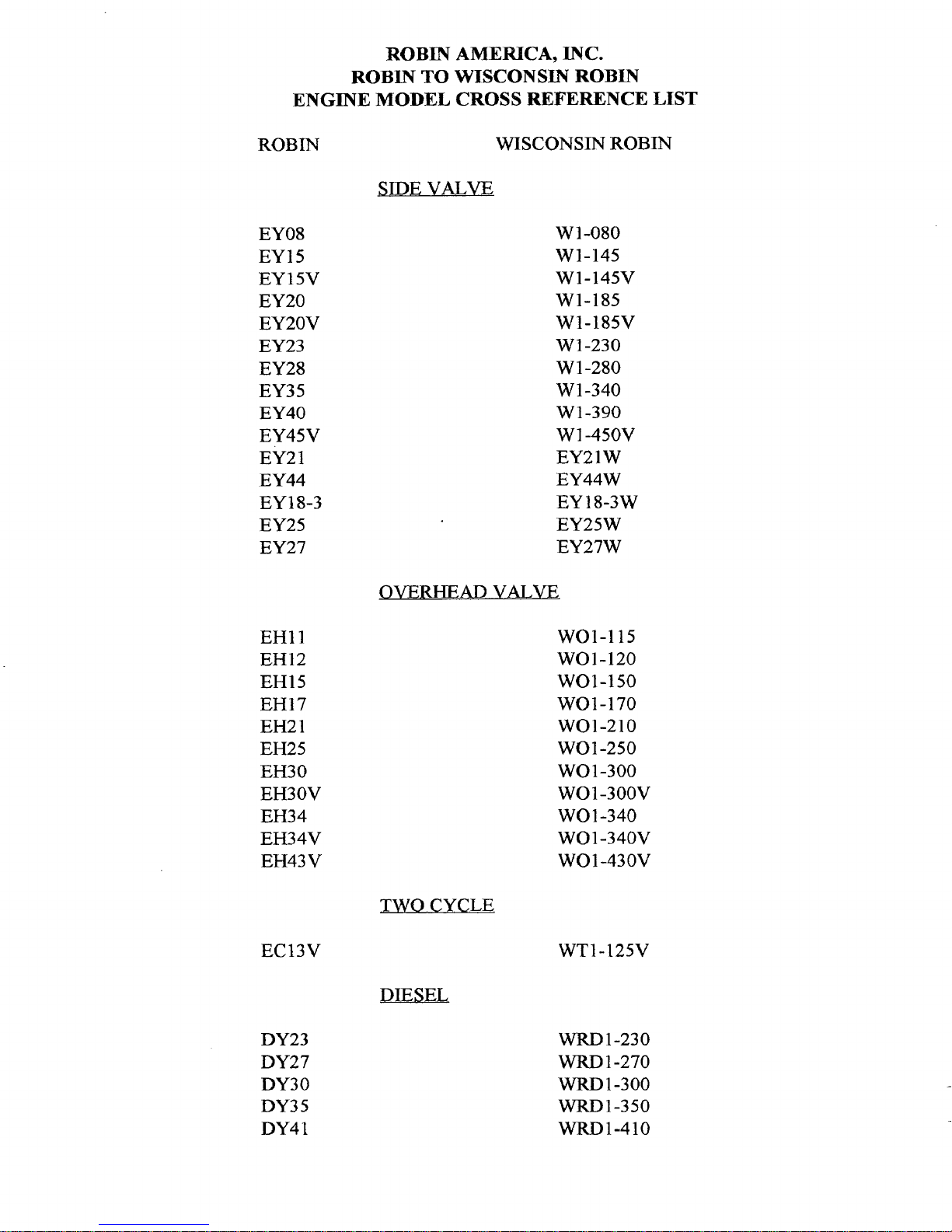
ROBIN
ENGINE
ROBIN
TO
MODEL
AMERICA,
WISCONSIN
INC.
ROBIN
CROSS REFERENCE LIST
ROBIN
EY 08
EY15
EY 15V
EY 20
EY20V
EY23
EY28
EY35
EY40
EY45V
EY2
1
EY44
18-3
EY
EY25
EY27
SIDE
VALVE
OVERHEAD
WISCONSIN
W 1-080
W1-145
W1-145V
W1-185
W1-185V
Wl-230
W 1-280
W 1-340
W
1-390
W
1
-450V
EY21W
EY44W
EY 18-3W
EY25W
EY27W
VALVE
ROBIN
EH11
EH12
EHl5
EHI
7
EH2
1
EH25
EH30
EH30V
EH34
EH34V
EH43 V
EC13V
DY23
DY27
DY30
DY3
5
DY4
1
TWO
CYCLE
DIESEL
WOI-115
WOI-120
WO1-150
WOI-170
wo1-210
WO1-250
WO
1-300
WO 1 -300v
WO1-340
WO
1
-340V
WO1-430V
WT1-125V
WRD
WRD
WRD
1-230
1-270
1-300
WRD1-350
WRD1-410
Page 3
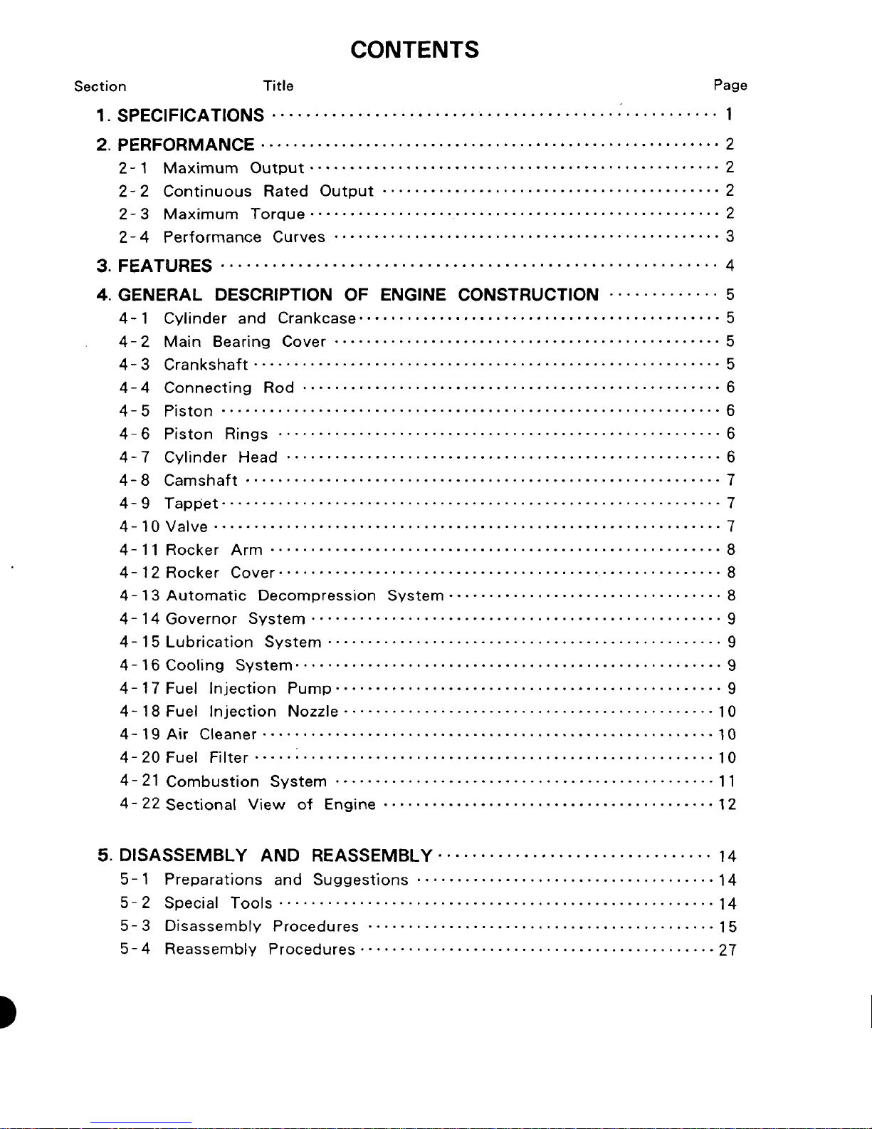
CONTENTS
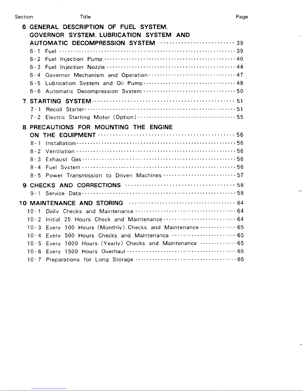
Section Title Page
Page 4
r
Page 5
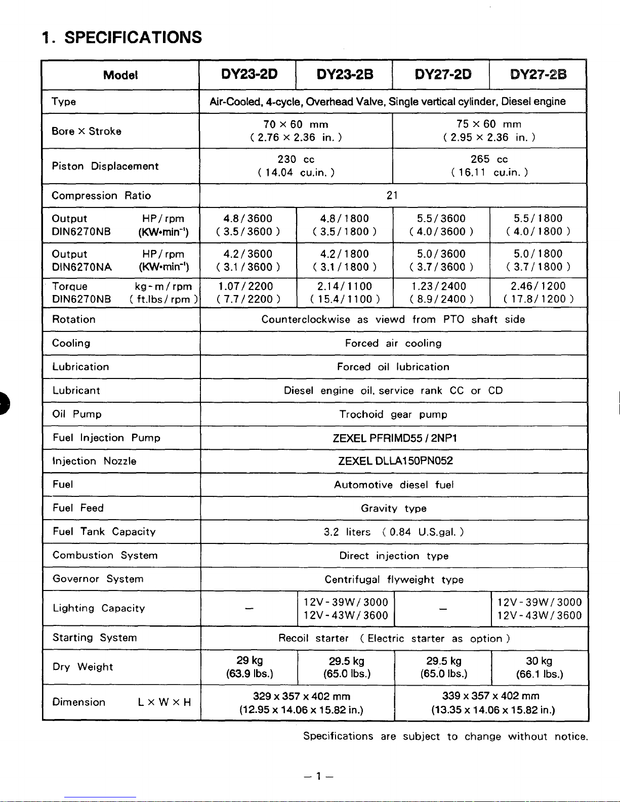
1.
SPECIFICATIONS
Model
Type
Bore X Stroke
Piston Displacement
Compression Ratio
output
DIN6270NB
output
DIN6270NA
Torque kg
DlN6270NB
Rotation
Cool
in
g
Lubrication
(
HP/ rpm
(Warnin”)
HP/ rpm
(KW-min”)
-
m
/
rpm
ft.lbs/
rpm
DY23-2D
DY23-2B
DY27-2
Air-Cooled. 4-cycle, Overhead Valve, Single vertical cylinder, Diesel engine
I
75 X 60 mm
(
2.95 X 2.36
(
16.1 1 cain.
/
3600
/
3600
/
2400
2400
265 cc
1
1
1
in.
1
)
5.5
/
1
800
(
4.0/ 1800
5.0
/
1
800
(
3.7/
1800
2.46/ 1200
(
17.W 1200
(
(
1.07/ 2200
1
(
I
I
I
70
(
2.76 X 2.36
(
14.04 cu.in.
4.8 / 3600
3.5 / 3600
/
3600
4.2
3.1
/
3600
7.7/
2200
Counterclockwise as viewd from PTO shaft side
X
230 cc
)
)
)
60
rnrn
in.
)
4.8
/
(
3.5/ 1800
4.2 / 1800
(3.1
/1800
2.14/ 1100
(15.4/11001
Forced oil lubrication
)
21
1
800
1
1
Forced air cooling
5.5
(
4.0/ 3600
5.0 / 3600
(
3.7
1.23
(
8.9/
1
1
1
Lubricant
Oil Pump
Fuel Injection Pump
Injection Nozzle
Fuel
Fuel Feed
Fuel Tank Capacity
Combustion System
Governor System
Lighting Capacity
Starting System
Dry Weight
I
I
I
(63.9
Diesel engine oil. service rank CC or CD
Recoil starter
Ibs.)
Trochoid gear pump
ZEXEL
ZEXEL
Automotive diesel
3.2 liters ( 0.84 U.S.gal.
Direct injection type
Centrifugal flyweight type
1
2V- 39W/
12V-43W/ 3600
(65.0
PFRIMD55
DLLAI
Gravity
3000
(
Electric starter as option
50PN052
type
Ibs.)
/
2NP1
fuel
(65.0
1
12V
-
39W
/
3000
12V - 43W / 3600
)
30
kg
lbs.) (66.1 Ibs.)
Dimension
LXWXH
329
x
357
x
402
mm
(1
2.95 x 14.06 x 15.82 in.)
Specifications are subject to change without notice.
-1-
339 x 357
(13.35 x 14.06
x
402
x
15.82
mm
in.)
Page 6
2-
1
MAXIMUM OUTPUT
The maximum output
of
an
engine is the output power
of
the engine operating with
its
throttle valve fully open after it has been broken in properly.
Therefore, a brand-new engine
or
an engine which has not been broken in properly may
not produce the maximum output.
2-2
CONTINUOUS RATED OUTPUT
The continuous rated output of an engine is the output power
of
the engine running
at the rated engine speed controlled by its governor system.
The operation of the engine at the continuous rated output
is
most
favorable
from
the
view point
of
engine life and fuel economy.
It
is
recommended, therefore, that the- equipment driven by the engine to be designed
to
require the engine power less than its continuous rated output.
2-3
MAXIMUM
TORQUE
The maximum torque indicates the torque at the output shaft when the engine
is
producing the maximum output.
-2-
Page 7
2
-
4
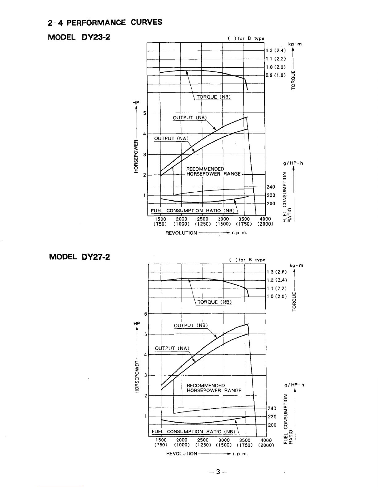
PERFORMANCE
CURVES
MODEL
DY23-2
HP
I
5
4
!z
23
W
v)
IT
0
I
2
1
MODEL
DY27-2
6
HP
I
5
4
9
5
P
0-3
W
v)
I1I
2
1
\
TORQUE
(NB)
kg
-
m
1.2 (2.4)
1.1
(2.2)
1
.o
(2.0)
i
3.9
(1.8)
2
c1:
I-
O
W
g/HP-h
240
220
y
200
g
z
0
I-
FUEL CONSUMPTION
RATIO
(NB)
\
I
I
L
L
I
&
-
1500
2000
2500
3000
3500 4/00
22
(750)
(1000)
(1250) (1500) (1750) (2000)
REVOLUTION
"----+
r.
p.
rn.
(
1
for
B
type
(750)
(1000)
(1250) (1500)
(1
750)
(21
1500 2000
2500
3000
3500
41
REVOLUTION
c
r. D.
rn.
kg-
m
.3
(2.6)
.2 (2.4)
.1
(2.2)
.o
(2.0)
Y
2
g/
HP-
h
h
-3-
Page 8
3.
FEATURES
3-
1
ECONOMICAL RUNNING
The direct injection system using the newly developed micro fuel injection pump assures
superior combustion efficiency and minimized fuel consumption.
3-
2
EXTREMELY QUIET OPERATION
0
The precisely synchronized fuel injection and refined combustion chamber allow lower
combustion pressure which results in reduced combustion noise.
Q
Blower housing and cylinder baffle are made from “DUMPING
SHEET”,
a special
material for insulating noise and vibration.
0
Larger super silent muffler and double element air cleaner reduce the exhaust and
intake noise.
3-
3
EASY STARTING
8
Light pull recoil starter and centrifugal automatic decompressor allow effortless
starting similar to a gasoline engine.
0
An auxiliary fuel inlet is provided for easy starting in cold weather.
An
3-
0
air check valve
4
LESS
In
addition to the reduced weight
VIBRATION
for
easy
air
bleeding
from
the fuel line.
of
reciprocating parts, a balancer shaft has been
adopted for extremely smooth running with less vibration.
a
The automatic decompressor prevents shaky vibration at stopping.
3-
5
HIGH PERFORMANCE
Die-cast cylinder head generates
a
stable swirl of air-fuel mixture which results in the
high output power and an exceptional fuel economy.
Its
flat torque characteristic provides tenacious running from slow speed to high speed.
3-
6
SUPERB RELIABILITY
The advanced Robin technology, such as well proven crankcase design, tension bolt
system
for
joining cylinder and cylinder head, and forced lubrication system, for longer
service life under the toughest operating conditions.
3-7
SMALL AND LIGHTWEIGHT
The newly developed micro fuel injection pump and crankcase structure originated in
the gasoline engine have .minimized the size and weight of the engine.
3-8
WIDE RANGE
OF
APPLICATIONS
Robin’s new air - cooled diesel engine series assures maximum adaptability to any
application.
0
Direct output type
Selection
of
P.T.O.
(D
type) and reduction type
shafts for various applications.
(B
type) are available.
Variable muffler exhaust direction.
0
Recoil starter and optional electric starter.
0
Strong power from small and lightweight body.
Q
Lower noise and less vibration.
-4-
Page 9
4.
GENERAL DESCRIPTION
OF
ENGINE
CONST
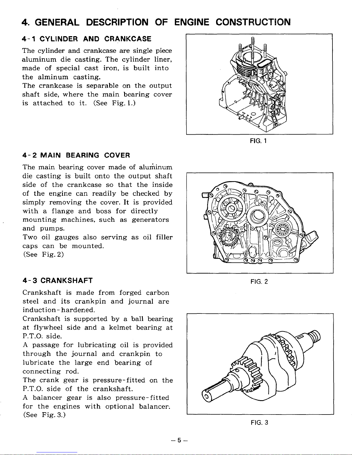
4-1
The cylinder and crankcase are single piece
aluminum die casting. The cylinder liner,
made of special cast iron, is built into
the alminum casting.
The crankcase is separable
shaft side, where the main bearing cover
is
CYLINDER
attached to
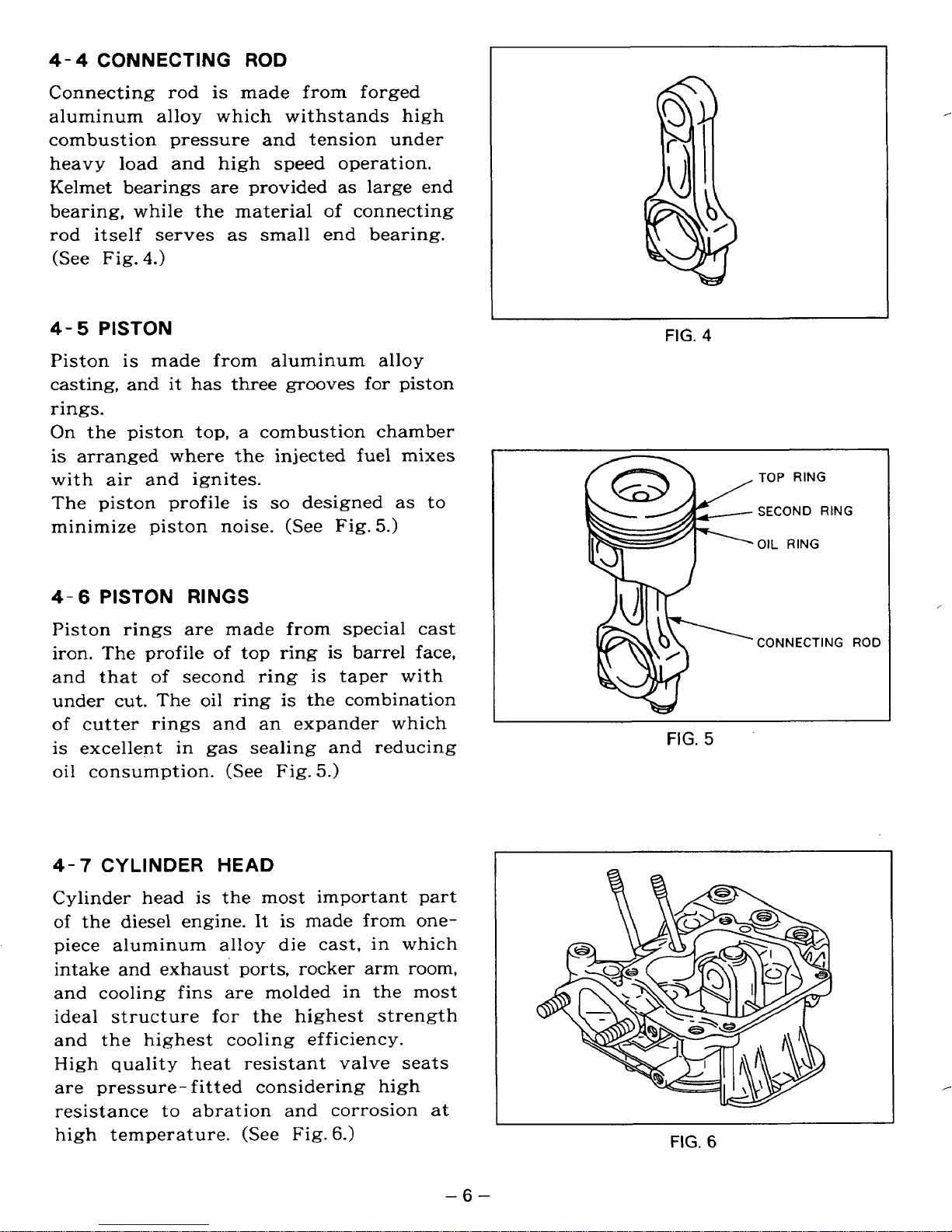
4-2
The main bearing cover made
die casting is built onto the output shaft
side of the crankcase
of the engine can readily be checked by
simply removing the cover. It is provided
with a flange and
mounting machines, such
and pumps.
Two oil gauges also serving
caps can be mounted.
MAIN
(See Fig.
2)
AND
it.
BEARING COVER
CRANKCASE
(See
so
boss
Fig.
for directly
on
the output
1.)
of
aluminum
that the inside
as
generators
as
oil filler
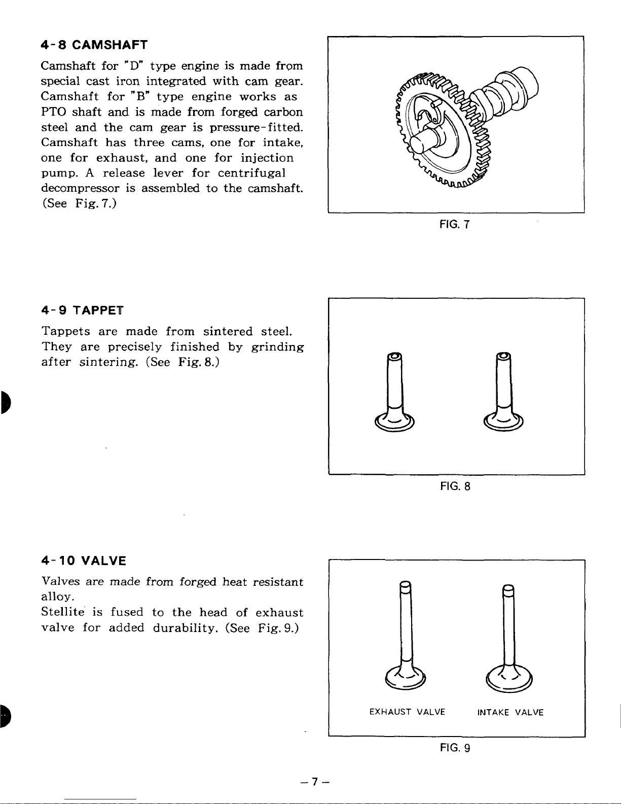
4-
3
CRANKSHAFT
Crankshaft is made from forged carbon
steel and its crankpin and journal are
induct ion
Crankshaft
at flywheel side and a kelmet bearing at
P.T.0:
A
passage for lubricating oil is provided
through the journal and crankpin to
lubricate the large end bearing of
connecting rod.
The crank gear is pressure-fitted
P.T.O. side of the crankshaft.
A
balancer gear is also pressure-fitted
for the engines with optional balancer.
(See Fig.
-
side.
3.)
hardened.
is
supported
by
a ball bearing
on
the
~~
FIG.
FIG.
2
3
-5-
Page 10
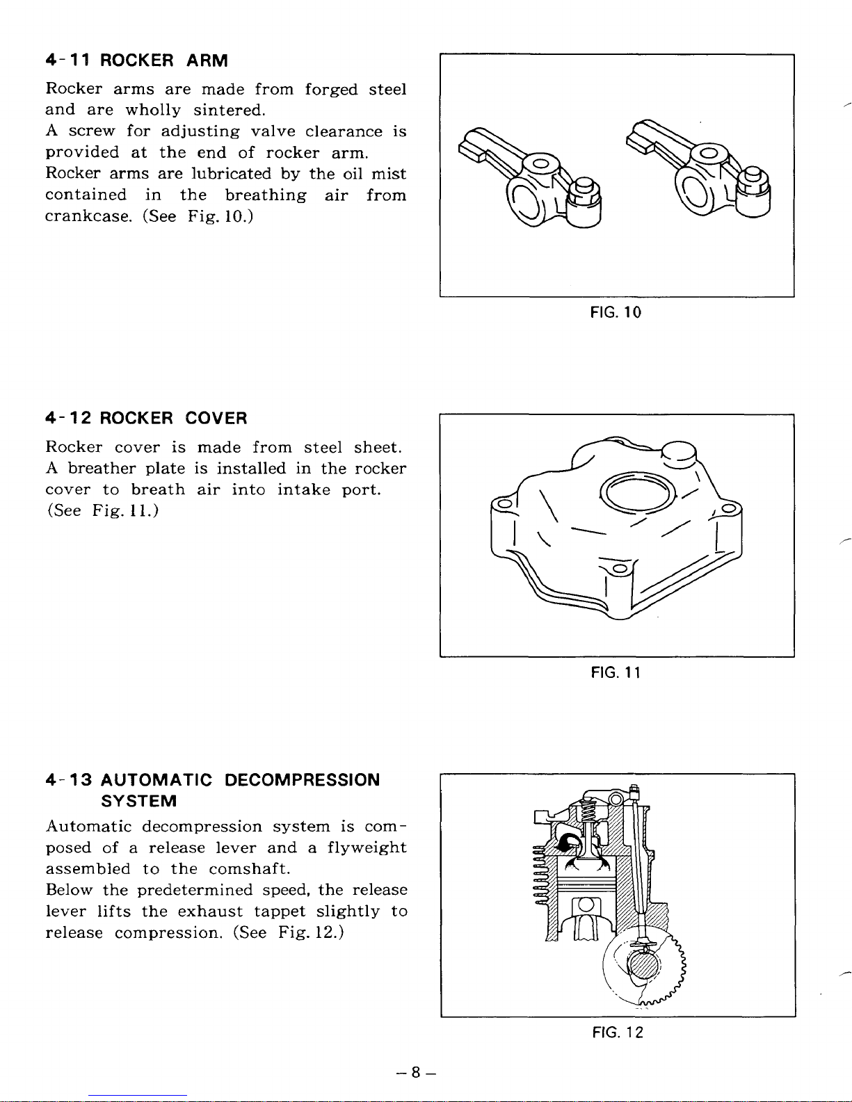
4-4
CONNECTING
ROD
Connecting
rod
is made from forged
aluminum alloy which withstands high
combustion pressure and tension under
heavy load and high speed operation.
Kelmet bearings are provided as large end
bearing, while the material
rod itself serves
(See Fig.
4-
5
Piston
4.)
PISTON
is
casting, and
made from aluminum alloy
it
as
has three grooves
small end bearing.
of
connecting
for
piston
rings.
On
the piston top, a combustion chamber
is arranged where the injected fuel mixes
with air and ignites.
so
The piston profile is
minimize piston noise. (See Fig.
designed as to
5.)
FIG.
,
4
TOP RING
SECOND RING
OIL RING
4-6
PISTON
RINGS
Piston rings are made from special cast
of
iron. The profile
and that
of
second ring is taper with
top ring is barrel face,
under cut. The oil ring is the combination
of cutter rings and an expander which
is
excellent in gas sealing and reducing
oil
consumption. (See Fig.
4-7
Cylinder head
of
CYLINDER
HEAD
is
the most important part
the diesel engine. It
5.)
is
made from onepiece aluminum alloy die cast, in which
intake and exhaust ports, rocker arm room,
and cooling fins are molded in the most
ideal structure
for
the highest strength
and the highest cooling efficiency.
High quality heat resistant valve seats
are pressure- fitted considering high
resistance to abration and corrosion at
high temperature. (See Fig.
6.)
FIG.
FIG.
,
CONNECTING ROD
5
,-
6
-6-
Page 11
4- 8 CAMSHAFT
Camshaft for
"D"
type engine is made
from
special cast
iron
integrated with cam gear.
Camshaft for
"B"
type engine
works
as
PTO
shaft and is made from forged carbon
steel and the cam gear
is
pressure-fitted.
Camshaft has three cams, one for intake,
one
for
exhaust, and one
€or
injection
pump.
A
release lever for centrifugal
decompressor
is
assembled to the camshaft.
(See Fig.
7.)
I
FIG.
7
4-
9
TAPPEU
Tappets are made from sintered steel.
They are precisely finished
by
grinding
after
sintering.
(See
Fig.
8.)
FIG.
8
4-
10
VALVE
Valves are made from
forged
heat resistant
alloy.
Stellite
is
fused to the head
of
exhaust
valve for added durability. (See
Fig.
9.)
EXHAUST VALVE INTAKE VALVE
FIG.
9
-7-
Page 12
4-
11
ROCKER ARM
Rocker arms are made from forged steel
and are wholly sintered.
A
screw for adjusting valve clearance is
of
provided at the end
Rocker arms are lubricated
in
contained
crankcase.
4-
12
ROCKER COVER
the breathing air from
(See
Fig. lo.)
rocker arm.
by
the oil mist
Rocker cover is made from steel sheet.
A
breather plate
is
installed in the rocker
cover to breath air into intake port.
(See Fig.
1
1.)
I
FIG.
10
4-
13
AUTOMATIC DECOMPRESSION
SYSTEM
Automatic decompression system
posed
of
a release lever and a flyweight
assembled to the comshaft.
Below
lever
release compression.
the predetermined speed, the release
lifts
the exhaust tappet slightly to
(See
Fig. 12.)
is
com-
-8-
FIG.
FIG.
11
/-
12
Page 13
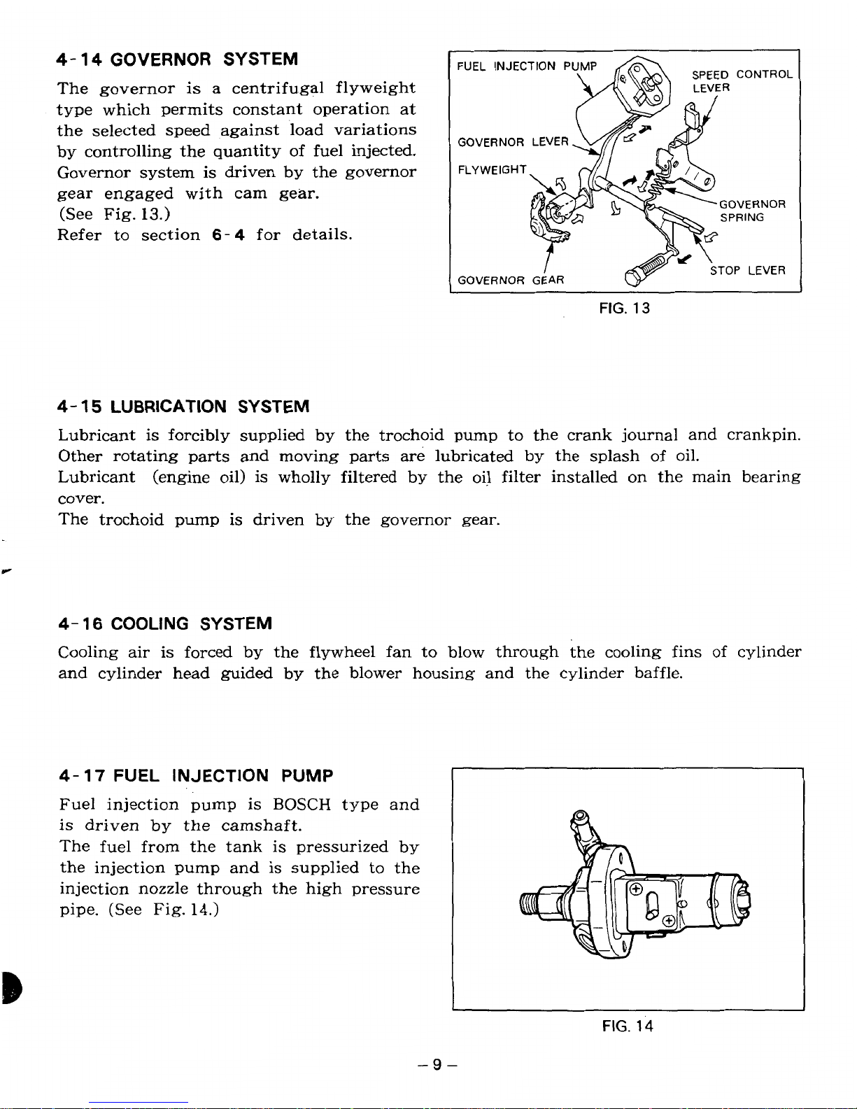
4-
14
GOVERNOR
SYSTEM
The governor is
a
centrifugal flyweight
type which permits constant operation at
the selected speed against load variations
by controlling the quantity of fuel injected.
Governor system
is
driven by the governor
gear engaged with cam gear.
(See Fig.
13.)
Refer
to
section
6-
4
for details.
GOVERNOR LEVER
FIG.
13
4-
15
LUBRICATION
SYSTEM
Lubricant is forcibly supplied by the trochoid pump to the crank journal and crankpin.
Other rotating
parts
and moving parts are lubricated by the splash
of
oil.
Lubricant (engine oil) is wholly filtered by the oil filter installed on the main bearing
cover.
The trochoid pump
is
driven by the governor gear.
c
4-
16
COOLING
SYSTEM
Cooling air
is
forced
by
the flywheel fan to blow through
the
cooling fins of cylinder
and cylinder head guided
by
the blower housing and the cylinder baffle.
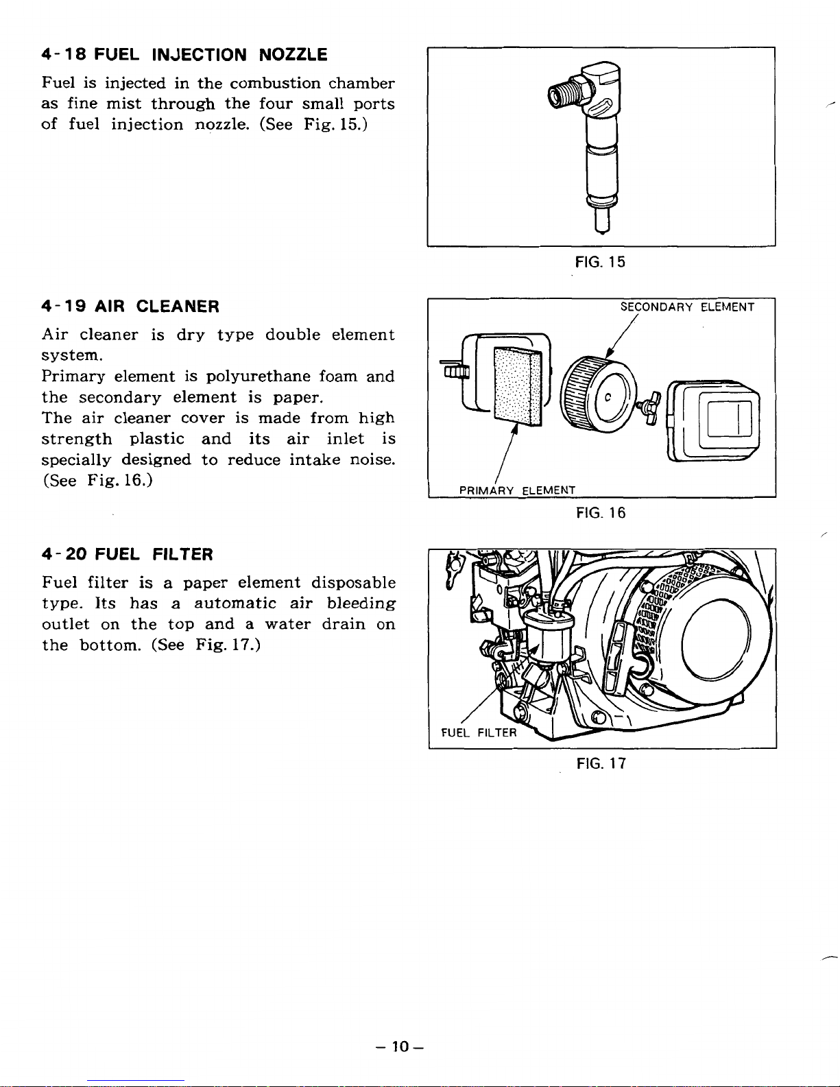
Fuel injection pump is
BOSCH
type and
is
driven
by
the camshaft.
The fuel from the tank is pressurized by
the injection pump and is supplied
to
the
injection nozzle through the high pressure
pipe. (See Fig.
14.)
FIG.
14
-9-
Page 14
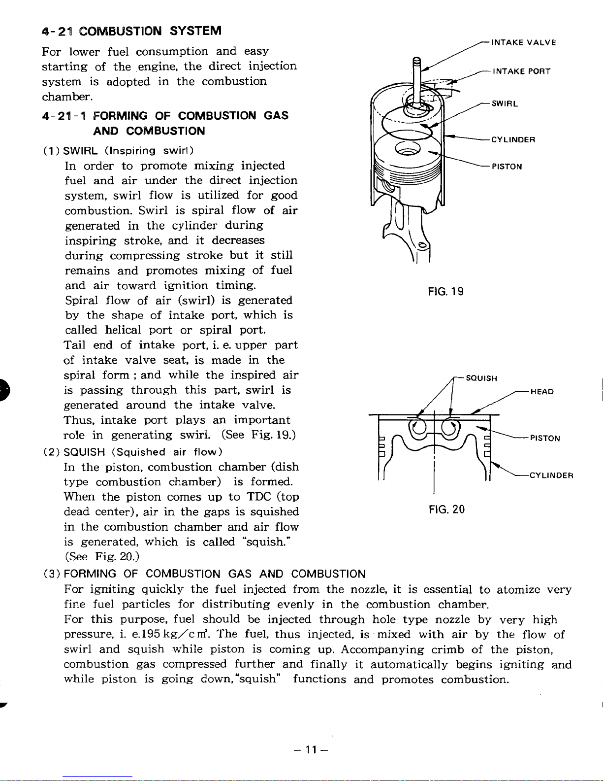
4-18
FUEL
INJECTION NOZZLE
Fuel is injected in the combustion chamber
as fine mist through the
four
small ports
of
fuel injection nozzle. (See Fig.
15.)
4- 19
AIR
CLEANER
Air
cleaner is
dry
type double element
system.
Primary element is polyurethane foam and
the secondary element is paper.
The air cleaner cover
is
made from high
strength plastic and its air inlet is
specially designed to reduce intake noise.
(See Fig.
16.)
4-
20
FUEL
FILTER
Fuel filter
is
a
paper element disposable
type.
Its
has
a
automatic air bleeding
outlet
on
the top and
a
water drain on
the bottom. (See Fig.
17.)
FIG.
15
SECONDARY
ELEMENT
/
PRIMARY ELEMENT
FIG.
16
/
FIG.
17
-
10-
Page 15
4-
21
COMBUSTION
SYSTEM
For
lower fuel consumption and easy
starting
of
the .engine, the
direct
injection
system is adopted in the combustion
chamber.
4-21-4
FORMING
OF
COMBUSTION
GAS
AND
COMBUSTION
(1
1
SWIRL
(Inspiring swirl)
In order to promote mixing injected
fuel and air under the direct injection
system, swirl flow is utilized for good
combustion. Swirl is spiral flow
of
air
generated in the cylinder during
inspiring stroke, and it decreases
during compressing stroke but it still
remains and promotes mixing of fuel
and
air
toward ignition timing.
Spiral flow
of
air (swirl) is generated
by the shape of intake
port,
which is
called helical port
or
spiral port.
Tail end of intake port, i. e. upper part
of
intake valve seat, is made in the
/INTAKE
VALVE
INTAKE
PORT
SWIRL
CY
LlNDER
PISTON
FIG.
19
/c
SQUISH
FIG.
20
spiral forrn : and while the inspired air
is
passing through this part, swirl is
generated around the intake valve.
Thus, intake port plays an important
role
in
generating swirl.
(See
Fig.
19.)
SQUISH
(Squished
air
flow)
In the piston, combustion chamber (dish
type combustion chamber)
is
formed.
When the piston comes up to
TDC
(top
dead center), air in the
gaps
is squished
in the combustion chamber and air flow
is generated, which is called “squish.”
(See Fig.
20.)
FORMING
OF
COMBUSTION GAS AND COMBUSTION
For igniting quickly the fuel injected from the nozzle, it is essential to atomize very
fine fuel particles for distributing evenly in the combustion chamber.
For
this purpose, fuel should be injected through hole type nozzle by very high
pressure, i. e. 195 kg/c
m’.
The fuel, thus injected, is ‘mixed with air by the flow of
swirl and squish while piston is coming up. Accompanying crimb of the piston,
combustion gas compressed further and finally it automatically begins igniting and
while piston
is
going down,“squish” functions and promotes combustion.
-
11
-
Page 16
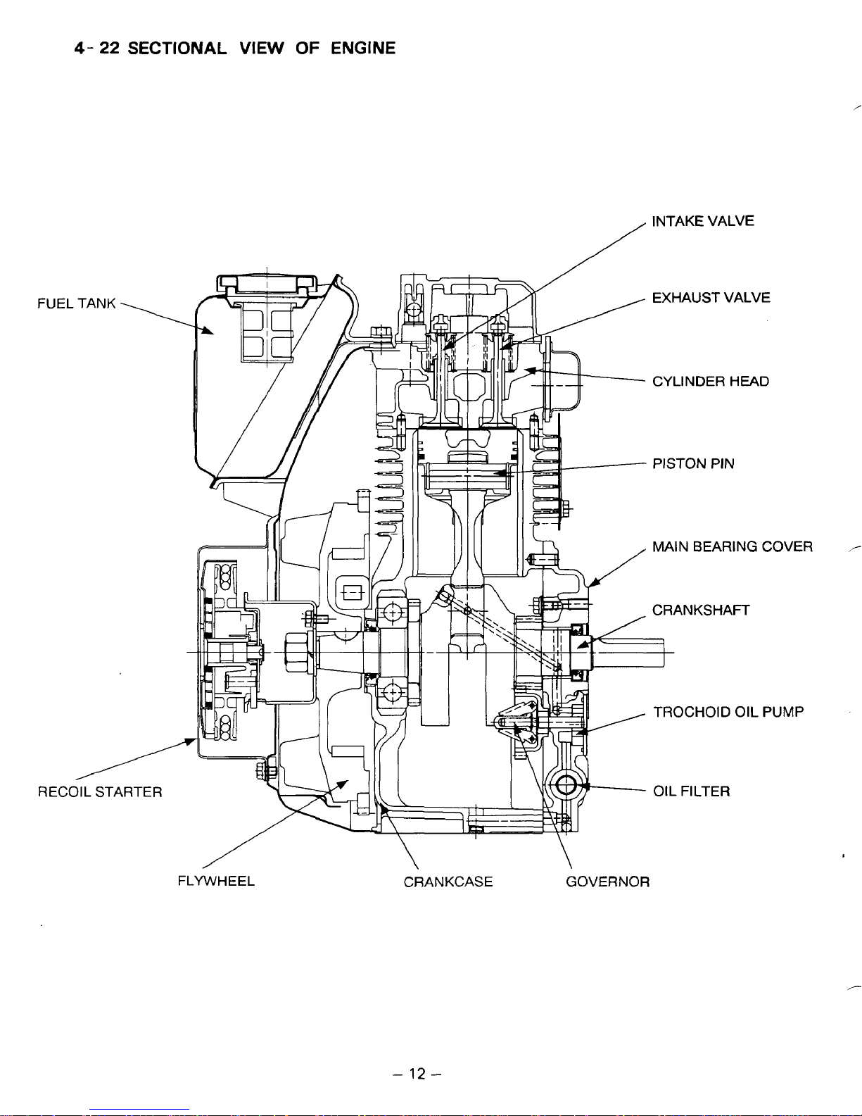
4-
22
SECTIONAL VIEW
OF
ENGINE
INTAKE VALVE
/
EXHAUST VALVE
k/
CYLINDER
PISTON
MA‘N
CRANKSHAFT
TROCHOID
HEAD
PIN
BEARING
OIL
COVER
PI
JMP
/
FLYWHEEL
\
CRANKCASE
-
12
-
\
GOVERNOR
Page 17
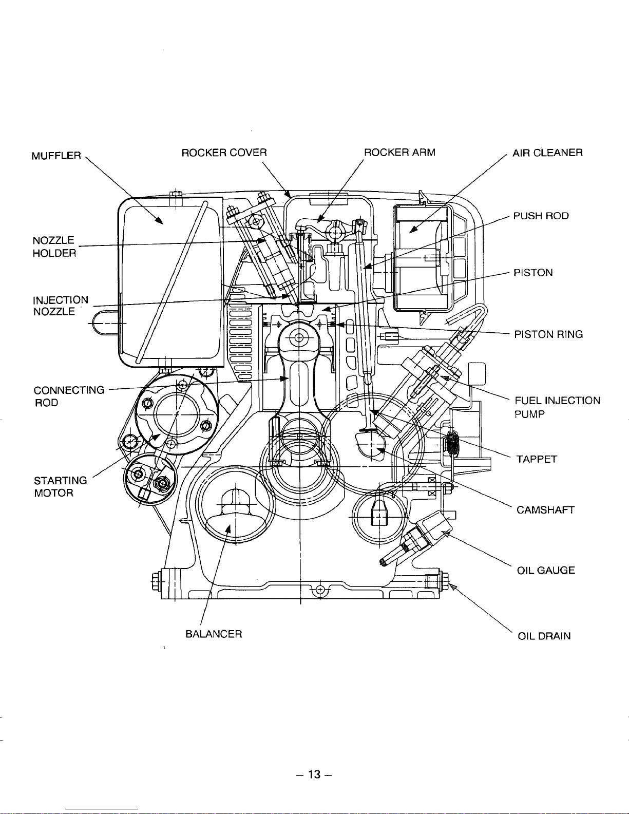
ROCKER COVER
AIR CLEANER
MUFFLER
\
\
/
PUSH
PISTON
PISTON RING
PUMP
ROD
FUEL
INJECTION
TAPPET
BALANCER
'
CAMSHAFT
OIL
GAUGE
\
OIL
DRAIN
-
13
-
Page 18
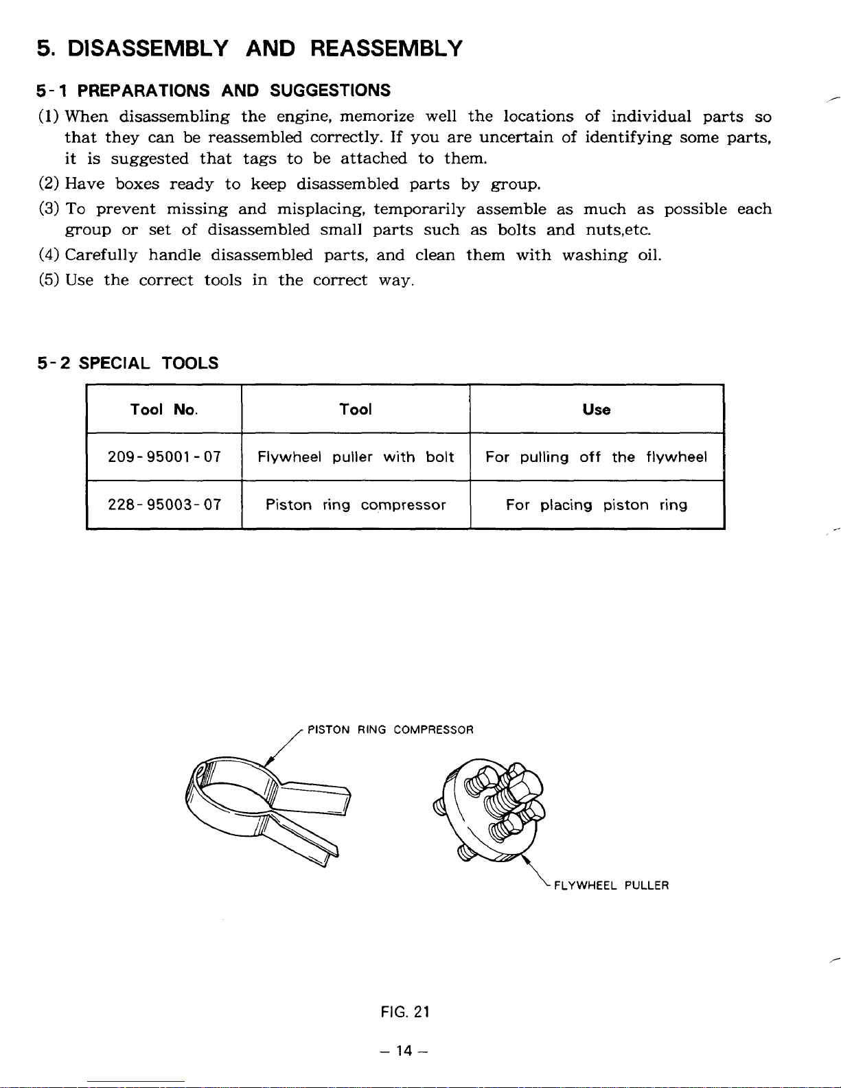
5.
DISASSEMBLY
5-
1
PREPARATIONS AND
(1)
When disassembling the engine, memorize well the locations of individual parts
that they can be reassembled correctly.
AND
REASSEMBLY
SUGGESTIONS
If
you
are uncertain
of
identifying some parts,
it is suggested that tags to be attached to them.
(2)
Have boxes ready to
(3)
To
prevent missing and misplacing, temporarily assemble as much as possible each
group
(4)
Carefully handle disassembled parts, and clean them with washing oil.
(5)
Use the correct tools in the correct way.
5-2
SPECIAL
or
set
of
TOOLS
disassembled small parts such as bolts and nuts,etc.
keep
disassembled parts by
group.
/-
so
Tool
209-
95001 - 07
228-
95003-
No.
07
Tool
Flywheel puller with
Piston ring cqmpressor
PISTON
RING
COMPRESSOR
f
bolt
Use
For pulling
For placing piston ring
off
the
flywheel
.
FIG.
-
14
21
-
FLYWHEEL
PULLER
/-
Page 19
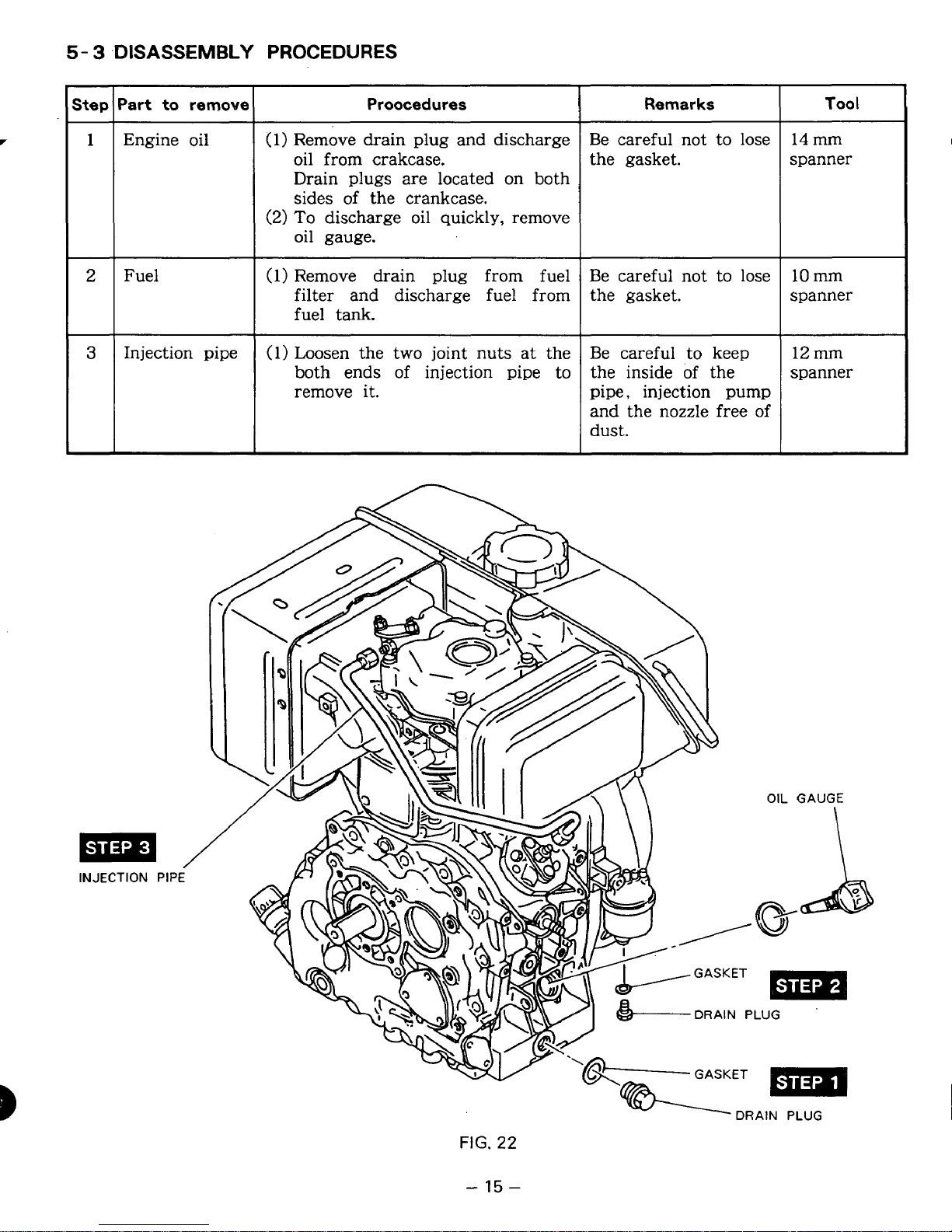
5-
3
-DISASSEMBLY PROCEDURES
-
Step
-
1
Engine oil
2
Fuel
-
3
Injection pipe
(1)
(2)
(1)
(1)
Proocedures
Remove drain plug and discharge
oil from crakcase.
Drain plugs are located on both
sides of the crankcase.
To
discharge oil quickly, remove
oil gauge.
Remove drain plug from fuel
filter and discharge fuel from
fuel tank.
Loosen the two joint nuts at the
both ends of injection pipe
to
remove it.
Remarks
Be careful not to lose
the gasket.
Be careful not to lose
the gasket.
Be careful
to
keep
the inside of the
pipe, injection pump
and the nozzle free of
dust.
Tool
14
mm
spanner
10
mm
spanner
12 mm
spanner
INJECTION
/
PIPE
-
15
-
Page 20
Step lPart to remove
’
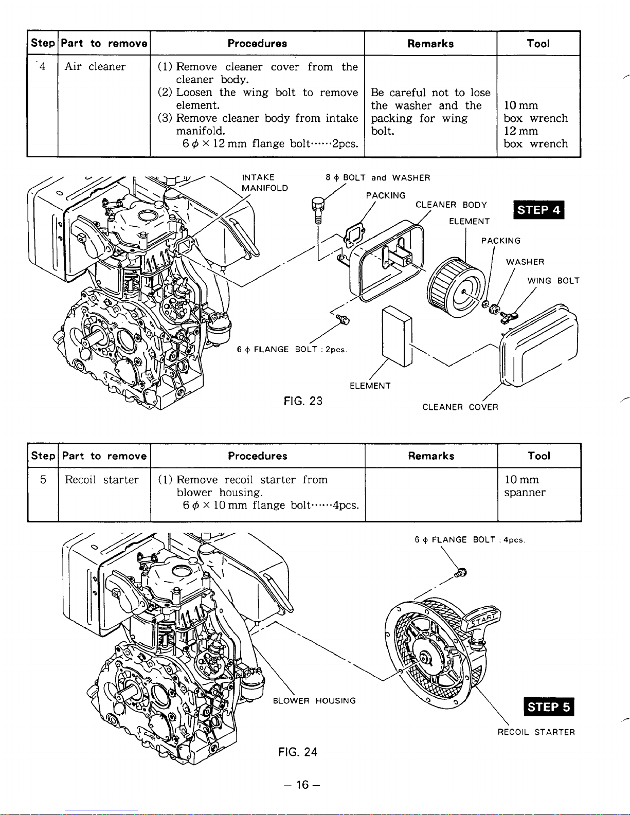
4
Air cleaner
Procedures
(1)
Remove cleaner cover from the
cleaner body.
(2) Loosen the wing bolt to remove
element.
(3)
Remove cleaner body from intake
manifold.
6
4
X
12
mm flange bolt...-..2pcs
8
0
BOLT and WASHER
Remarks
Be careful not to lose
the washer and the
for
packing
bolt.
wing
.
Tool
10 mm
box wrench
12 mm
box wrench
I
Step I Part
5
Recoil
to
remove
starter
I
(1) Remove
blower housing.
6
4
Procedures
recoil
x
10
mm flange bolt**..**4pcs.
starter
from
PACKING
ELEMENT
I
CLEANER BODY
Remarks
3
spanner
FIG.
-
16
HOUSING
24
-
6
0
FLANGE BOLT
:
4pcs.
m
RECOIL STARTER
Page 21
step
I
Part
to
remove
Procedures
I
Remarks
Tool
6
7
Fuel
tank
Muffler
6
+
BOLT
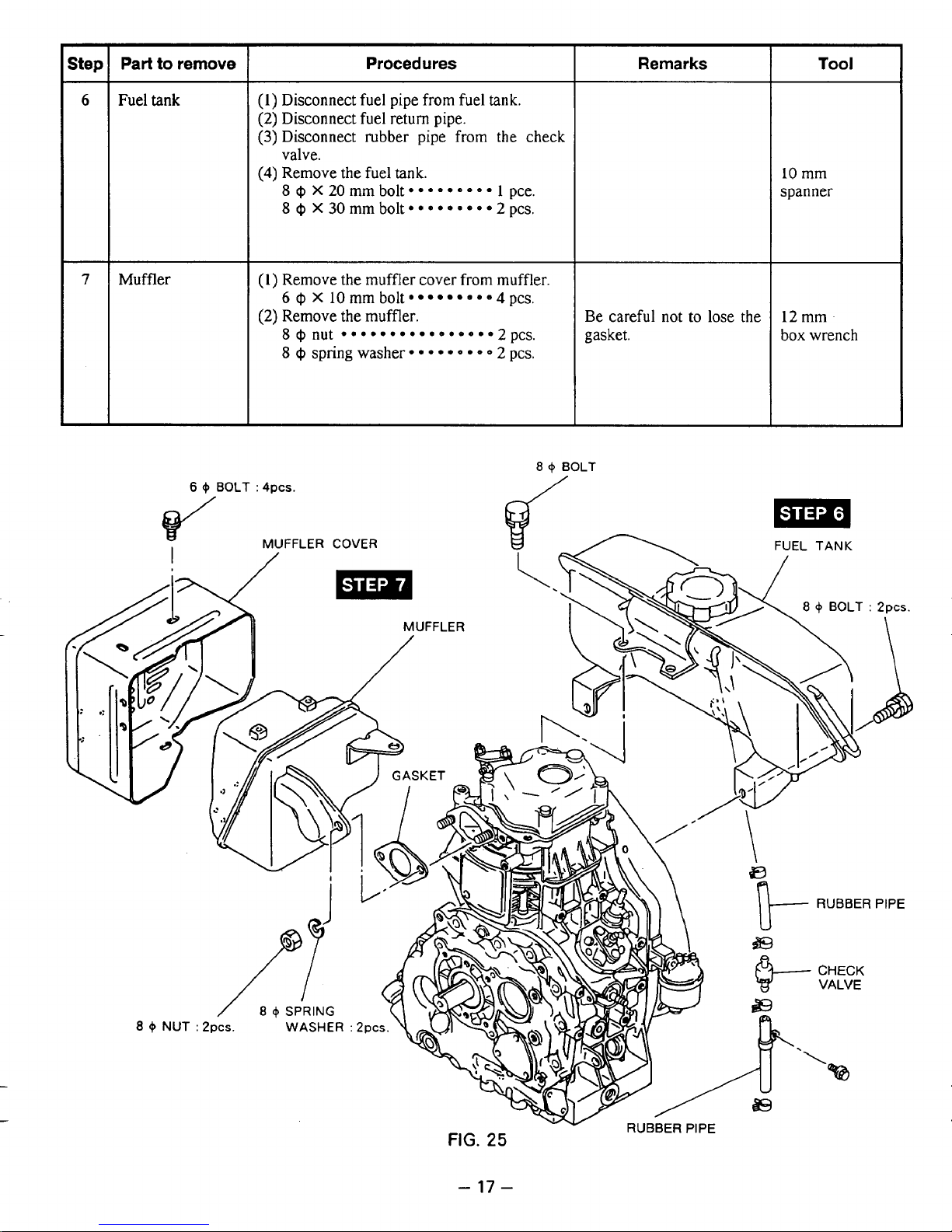
(1)
Disconnect fuel pipe from fuel
(2)
Disconnect fuel return pipe.
(3)
Disconnect rubber pipe from the check
tank.
valve.
(4)
Remove
8
8
(1)
Remove the muffler cover from muffler.
6
(2)
Remove the muffler.
8
8
:
4pcs.
the
fuel
tank.
Q
X
20mmbolt*****e.e* 1 pce.
@
X30mmbolt*****~***2pcs.
@
X
10
mm bolt
@nut
9
e
*
*
4
pcs.
Qspringwasher*****~*~~2pcs.
a
/
+
BOLT
Be careful
gasket.
not
to
lose the
10
mm
spanner
12
mm
box wrench
-
17
-
Page 22
Step Part to remove Procedures Remarks Tool
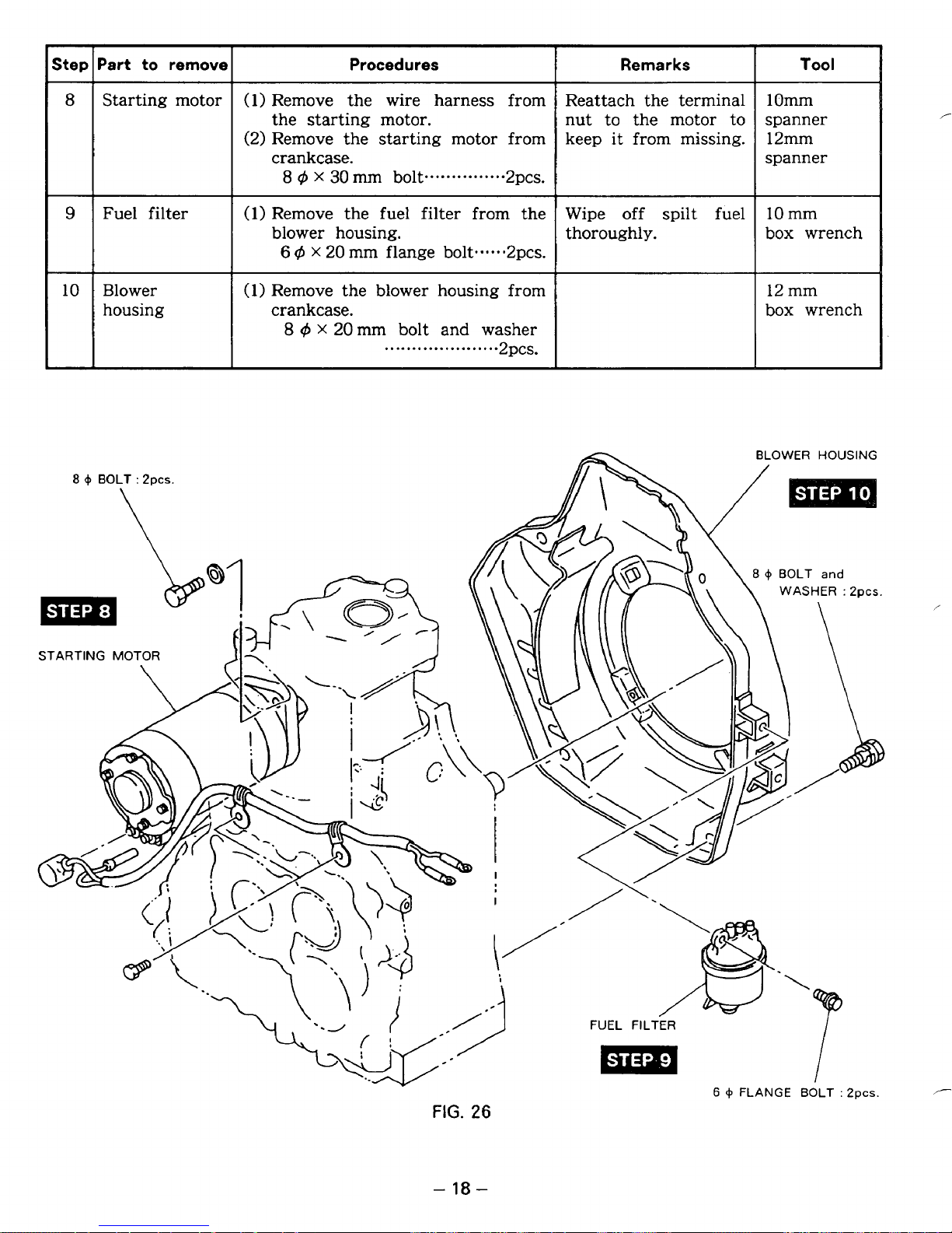
8
Starting motor
(1)
Remove the wire harness from Reattach the terminal 1Omm
the starting motor. nut to the motor to spanner
(2)
9
Fuel filter
Remove the starting motor from keep
crankcase.
8
4
x
30
mm bolt
(1)
Remove the fuel filter from the Wipe off spilt fuel
...............
2pcs.
it
from missing. 12mm
spanner
10
mm
blower housing. thoroughly. box wrench
6
q-5
X
20
10
Blower
housing
mm flange bolt.....*2pcs
(1)
Remove the blower housing from
crankcase.
8
q5
x
20
mm bolt and washer
.....................
.
12 mm
box wrench
2pcs.
-
18
-
Page 23
-
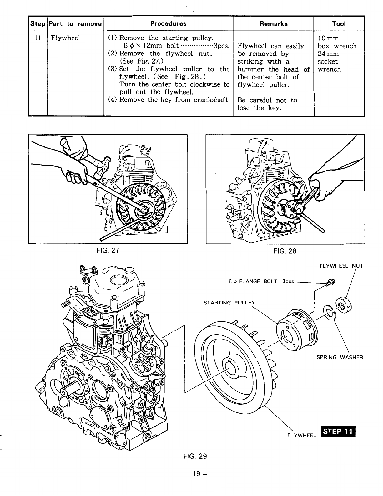
Step
11
Part
to
remove
Flywheel
Procedures
Remarks
(1)
Remove the starting pulley.
(2)
Remove the flywheel nut.
striking with a
(See Fig.
27.)
be removed
by
(3)
Set the flywheel puller to the
hammer the head of
flywheel. ( See Fig.
28.
)
the center bolt of
Turn the center bolt clockwise to
flywheel puller.
pull out the flywheel.
(4)
Remove the key from crankshaft.
Be careful not to
6
,$
X
12m
bolt
.......
.....
...
3pcs.
Flywheel can easily
lose the key.
FIG.
27
Tool
10
mm
box wrench
24
mm
socket
wrench
v
FIG.
28
FLYWHEEL
NUT
6
+
FLANGE BOLT
:
3pcs.-@
STARTING PULLEY
SPRING WASHER
FLYWHEEL
FIG.
29
-
19
-
Page 24

Step
-
12
13
Part
to
remove
Cylinder
baffle
Rocker cover
Procedures
Remarks
Tool
(1) Remove the cylinder baffle from
cylinder.
6
q5
X
10
~~
(I)
Remove the rocker cover from
cylinder head.
6
4
mm flange bolt-.-..-lpce.
X
40
mm flange bolt-......lpcs
.
10
box
mm
wrench
Fuel injection
nozzle
6
4
NUT
:
NOZZLE BRAC
FUEL
INJECTION
2pcs.
”-e9
NOZZ
(1)
Remove the bracket, nozzle.
6
4
(2)
Remove the fuel injection nozzle
from
I
..............................
nut 2pcs.
cylinder head.
Be careful not to lose
the gasket at the
bottom end of the
nozzle.
-6
ROCKER COVER
4
FLANGE
BOLT
:
4pcs.
LANGE
BOLT
FIG.
-20-
30
Page 25

Step Part to remove
15
Rocker arm
16
Cylinder head
Procedu.res
(1)
Loosen the adjusting bolts on the
rocker arms.
(2)
Push
the
the rocker shaft out from
cylinder
head to remove
rocker arms.
(3)
Remove the push
rods.
Remarks
Make the rocker arms
the
and push rods
distinguishable
of
Tool
10
mm
spanner
screw driver
intake side and
exhaust side.
(1)
Remove the cylinder head
cylinder. spacer.
8
4
flange nut
.......
.....
from
.
....
4pcs.
8
6
FRANGE NUT
Be careful of the
:
4DC.s.
12
mm
socket
wrench
ADJUSTING
BOLT
P
ROCKER
CYLINDER
HEAD
\
I
ARM
ROD
-
FIG.
21
-
32
Page 26

Step
-
17
-
18
)art
to remove
Fuel injection
pump
Main bearing
cover
Procedures
(1) Remove the fuel injection pump
from crankcase.
6
4
nut
..............................
2pcs.
(1) Remove the bolts joining the
main bearing cover and
crankcase.
8
@
X
35
8
@
(2)
Lightly tapping with a plastic
mm bolt..-.----.--. 1 lpcs.
x
40mm bolt
...............
1 pce.
hammer, remove the main
bearing cover from the
Fig.
crankcase. (See
33.)
Remarks
Be
careful of the
position of the
control
Be careful not
rack.
to
damage the oil seal.
Tool
10 mm
socket
wrench
~ ~~
12 mm
box wrench
plastic
hammer
6
+
NUT
:
2pcs.
Page 27

Step
19
20
'art to remove
F
Camshaft
Balancer
(Optional
part)
Procedures
(1)
Remove the camshaft from the
crankcase. (See
(2)
Remove the tappets from the
Fig.
crankcase.
i
(1)
Remove the balancer from the
~
crankcase.
35.)
Remarks
(1)
To
prevent the
tappet from falling
and getting damages,
put the crankcase
injection pump side
down.
(2)
Put marks on the
tappets to distinguish
intake tappet
from
exhaust.
Be
careful
of
the
spacer on the
balancer shaft.
Tool
SPACER
FIG.
-
23
36
-
Page 28

Step
21
r
'art
to
Connecting
rod
remove
Procedures
(1)
Scrape off the carbon deposit
from the piston top and cylinder.
(2)
Remove the connecting rod bolts
and the large end cap.
(3)
Turn the crankshaft to the top
dead center.
Then, push the connecting rod
up and pull the piston and
connecting rod out from the
cylinder.
Remarks
10
box
Tool
mm
wrench
22
PISTON
PISTON
Piston and
piston pin
RING
PIN
(
1)
Remove the two clips from the
piston at the both ends
of
pin.
(2)
Push the piston pin out from the
piston.
Remove the piston from the
connecting
(3)
Remove the piston rings from
rod.
the piston by spreading their
open ends.
CLIP
piston
Be careful not to give
damages to the
piston and connecting
rod.
Be careful not
to
break the rings by
spreading too much
or twisting them.
CONNECTING
LARGE
ROD
END BEARING'
/
IU
I
I
/
Page 29

Step
Tool
Remarks
Procedures
Part
to
remove
23
The ball bearing
(1)
Lightly
tap
the crankshaft end
Crankshaft
at the flywheel side
using
a
(See
Fig.
38.)
from the crankshaft.
crankshaft.
plastic hammer to remove it
comes
off with the
FIG.
38
CRANKSHAFT
\
t
FIG.
39
-
25
-
Page 30

Part to remove Procedures
Step
I
Intake and
exhaust valve remove the retainer locks from
(1)
Press the valve springs and
the valve stems. (See
(2)
Remove the valves from the
cylinder head.
Fig.
40.)
Remarks
Put marks on the
valves, valve springs
and spring retainers
to distinguish them
for
intake side from
exhaust side.
Tool
~~ ~
.pliers
3
Oil
h
filter
FIG.
(1)
Remove the oil filter from the Be careful not to lose
main bearing cover. the
6
4
40
X
12mm
flange bolt...---2pcs.
0-
10
mm
ring. spanner
8-
I
&“----
RETAINER
STEM
LOCK
SEAL
MAIN
BEARING
COVER
7-
OIL
FILTER
6
+
FLANGE
J
FIG.
41
-
26
-
BOLT
:
2pcs
VALVE
Page 31

EASSEMBLY
PROCEDURES
PRECAUTIONS
FOR
REASSEMBLING
(1)
Clean parts thoroughly before reassembly.
(2)
Scrape
off
all
carbon deposits
from
cylinder head, piston top and piston ring grooves.
(3)
Check lips
of
oil
seals. Replace
oil
seal
if
a
lip
is
damaged.
(4)
Replace all gaskets with new ones.
(5)
Replace keys, pins, bolts, nuts, etc.,
if
necessary.
(6)
Torque bolts and nuts to specification refering to the “Table
of
tightening torque”.
(7)
Apply
oil
to
rotating
and
sliding portions.
(8)
Check
and
adjust clearances and end plays where specified in this manual.
Pay most attention to cleanliness
of
piston, cylinder, crankshaft, connecting rod
and
bearings.
Apply
oil
to lips before reassembly.
5-
4- 1 CRANKSHAFT
(1)
Fit the oil seal guide
onto
the
end
of
the crankshaft, and insert the
crankshaft
into the crankcase.
U/
OIL
SEAL
GUIDE
FIG.
42
-
27
-
Page 32

5-
4-
2
PISTON AND PISTON
RING
(1)
If
the piston ring expander is unavailable, install the piston rings
by
placing
the
open
ends
over
the
top
land
of
the piston and
spreading
the
ring ends
only
far
enough
to
slip
them into the correct ring grooves.
1.
Pay attention not to break the piston
ring
by twisting.
2.
Install the oil ring first followed
by
the second ring and then top ring.
3.
Second
ring have “N”marks stamped on
the
ring
ends. These
”N”marks
have to face upward when installed on
the
piston.
OPEN ENDS
OF
PISTON
RING
‘
I
FIG.
43
Top ring
Barrel face
Second
ring
Taper
......
......
......
...
...
...........
...........
....................
.........
Oil
ring Cutter
ring
with
expander
:e
......
.......
................
......
...........
..........
FIG.
44
(2)
Assemble the piston and connecting
rod
with the piston pin.
I
1.
Set the “D”or “B”mark stamped on piston top
to
the
“FAN”mark
side
of
the
2.
Apply
enough oil to the
small
end of the connecting rod.
3.
Be
sure
to set
the
clips
on
both ends
of
the piston
pin.
connecting
rod.
I
,
-
28
-
Page 33

assembly into the cylinder.
Use the piston ring compressor
to
hold
the piston rings.
The “FAN” mark
of
the connecting rod
have to face flywheel side when
assembled. (See Fig.
45.)
1.
Apply enough oil to the piston rings,
connecting rod bearings and cylinder
bore before assembly.
2.
Set the open end
of
the piston rings
90
degrees apart from
one
another
before assembly.
5-4-3
CONNECTING
ROD
(1)
Turn the crankshaft
to
the bottom
dead center, lightly hammer the piston
head until the connecting rod contacts
the crankpin, and assemble,
(2)
When reassembling the large end cap,
match the alignment mark
on
the rod.
1.
No.
lock washer
is
used for the
2.
Tighten the rod bolts securely
by
the
Tightening torque
:
180-200
Kg-
cm
connecting
rod
bolts.
specified tightening torque.
PlSTON
RING
COMPRESSOR
FIG.
45
FIG.
46
-
29
-
Page 34

5-
4- 4
BALANCER (Optional part)
Install the balancer to the crankcase.
Align the matching marks
gear and crank gear as shown in Fig,
of
the balancer
47.
FIG.
47
-I
AFT
5-4-
5
TAPPET AND CAMSHAFT
(1)
Insert the tappets into the tappet holes
of
the crankcase.
Be sure to assemble the intake tappet
to intake side and exhaust tappet to
exhaust side.
(2)
Install the camshaft into the crankcase
matching the timing marks
crank gear and cam gear. (See Fig.
on
the
48.)
FIG.
48
,
-
30
-
Page 35

5-4-
6
MAIN BEARING COVER AND GOVERNOR GEAR
(1)
Installation
of
governor gear
shaft
set.
MAIN BEARING COV VERNOR
GOVERNOR GEAR
S
243-4501 1-01
(GOVERNOR GEAR SHAFT
FIG.
49
GEAR
SET)
a) Insert
GOVERNOR
GEAR
SHAFT
to the main bearing cover.
b)
Put
GOVERNOR
GEAR
on
the governor gear shaft.
c) Press
the
iron sleeve
of
governor gear using
a
pressing machine
to
fit
on the governor
gear shaft. (See
Fig.
50.)
Be sure to make a clearance
of 1 mm
(0.04
in) between governor gear and mounting
boss
of
main
bearing cover. (See Fig.
5
1.)
FIG.
50
FACE
OF
MAIN BEARING COVER
S
THE IRON SLEEVE
OVERNOR GEAR
I
CLEARANCE
1
rnm
(0.04in)
FIG.
51
1.
When replacing the governor gear or governor gear shaft, be sure to replace them
2.
Do
not press the plastic part
of
governor gear at assembling.
at the same time.
-
31
-
Page 36

(2)
Install the main bearing cover
to
the crankcase.
Adjust the side clearance for the crankshaft, camshaft
specified values using the proper spacer and
thrust
and
washer.
balancer shaft to
the
SIDE
CLEARANCE
ADJUSTING
DEVICE
CRANKSHAFT
0.1
-0.3
THRUST
T
T
T
WASHER
=
0.1
=
0.2 mm
=
0.3
mm
mm
mm
.
D
type
I
0.05-0.25 mm
SPACER
T = 0.8
T=
1.0
CAMSHAFT
I
mm
mm
type
0.05-0.3 mm
SPACER
T = 0.6
T
=.0.8
T
=
1.2
mm
mm
mm
BALANCER
SHAFT
I
0.05-0.25 mm
SPACER
T
=
0.8
T
=
1.0
T
=
1.2
I
mm
mm
mm
A
-
32
,
-
Page 37

1.
As the governor gear is mounted on
the main bearing cover side, install
the main bearing cover while checking
that
it
meshes
with
the teeth of the
cam gear.
(See
Fig.
53.)
2.
If
the replacement of oil seal is
necessary, press-fit the new oil seal
before installing the main bearing
cover.
3.
Apply oil to the ball bearing and
oil
seal rip before installing the main
bearing cover.
4.
Be careful not to injure the oil seal
rip at reassembly.
Use
oil seal guide
to protect
it.
1
FIG.
53
(3)
Tighten the twelve bolts evenly to join the main bearing cover
to
the crankcase.
8
@
X
35
mm
bolt and washer assy.
-
-
1 lpcs.
8
q5
X
40
mm bolt and washer assy.
.
* * * *
-
-
1
pce.
Tightening torque
:
170-190 kg- cm
Attach the two clamps to
the
main bearing cover
for
electric start model.
5-4-*7
FLYWHEEL
AND
STARTING
PULLEY
(1)
Put
the woodruff key (for magneto) in place.
(2)
Wipe off oil and grease thoroughly
from
the tapered portion
of
the crankshaft and
flywheel center hole.
(3)
(
ELECTRIC
START
MODEL
)
'
Install the charge coil to the crankcase.
(4)
Install the flywheel to the crankshaft.
Tighten the flywheel nut with
a
spring
washer.
Tightening torque
:
600-650
kg-
cm
(5)
Attach the starting pulley to the flywheel.
6
@
x
12mm bolt and washer
assy.
-. . -.
3pcs.
'Tightening torque
:
70-90 kg-cm
-
33
-
Page 38

5-4-8
FUEL INJECTION PUMP
(1)
Measure the distance between the face
of
the cam base and the pump
mounting face of the crankcase.
(See
Fig.
54.)
Select the gasket (injection pump)
of
the proper thickness
so
as the distance
to be adjusted to
66
-+
0.05mm.
The gasket (injection pump) of three
different thickness are available.
(T
=
0.1
mm,
T
=
0.2
mm
and
T
=
0.3
mm)
(2)
Apply
sealant
(THREE BOND
1215)
to the both side
of
the gasket (injection
pump).
(3)
Install the fuel injection pump to the
crankcase checking the control rack
of the injection pump to engage with
the governor lever correctly.
(See Fig.
55.)
FIG.
54
/-
FIG.
55
,
-
34
-
Page 39

5-4-9
CYtlNDER
HEAD
(1)
Assemble the intake valve and exhaust
valve to the cylinder head.
a) Remove carbon deposits from valves,
valve seats, intake and exhaust
ports,
and valve guides.
b)
If
the valve face
is
worn out, replace
it
with
a
new one.
c) Check the stem seal in the intake valve
guide for
a
damage.
If the rip of the stem seal is injured,
replace
it
with a new one.
d) Insert the intake valve and the exhaust
valve into the valve guide.
e)
Assemble the valve springs, spring
retainers and the retainer locks.
(2)
Check the clearance between the piston
top and the. cylinder top.
(See Fig.
56.)
Select the proper SPACER (head)
so
as the clearance to be within
0.6-0.7
mm.
SPACER (head) of two different
thickness
(T
=
0.6
mm and
0.7
mm)
are
available. (See Fig.
56.)
(3)
Put the cylinder head on the cylinder.
(4)
Apply
sealant (THREE
BOND
1215) to
the two studs on the rocker shaft side.
Apply oil to the other two studs.
(See
Fig.
57.)
(5)
Tighten the four flange nuts evenly
in three steps by the following
tightening torque.
100 kg-cm
200
kg- cm
300-330 kg-
cm
1st step
.............
2.nd step..
...........
3rd step
.............
5-4-
10
ROCKER
ARMS
(1)
Insert the push rods into the tappets
in
FIG.
56
I
APPLY
THREE
BOND
1215.
FIG.
57
the crankcase.
(2)
Apply oil to the rocker arms and install them to the cylinder head using the rocker
shaft. Attach the snap rings to the both ends of the rocker shaft.
-
35
-
Page 40

5-
4-
11
VALVE CLEARANCE
ADJUSTMENT
(1)
Set the crankshaft to the top dead
center by matching the mark
"T"
of the
flywheel with the
"TOP"
mark of the
crankcase.
(2)
Loosen the lock nut on the rocker arm
and turn the adjusting
screw
to adjust
the clearance between the rocker arm
and valve stem end to
0.1
mm.
(both intake and exhaust)
Then, tighten the lock nut.
Adjust the valve clearance while 'the
engine
is
cold.
(3)
Turn the flywheel
by
hand and check
the valves move smoothly without
hitting piston.
FIG.
58
0
INTAKE, EXHAUST VALVE TIMING
The valve clearance shall increase to
0.4
mm while engine is running hot.
In
this condition, the valve timing
is
as
follows
:
Intake valve opens at 16" before TDC.
Intake valve closes at
54"
after BDC.
Exhaust valve opens at
54"
before
BDC.
Exhaust valve closes at
14"
after
TDC.
TDC (TOP DEAD CENTER)
INTAKE VALVE
16"
14"
EXHAUST VALVE
(4)
Apply
sealant
(THREE
BOND
1215)
to
the joining surface
of
the
rocker cover.
INTAKE VALVE
CLOSES.
BDC (BOTTOM DEAD CENTER)
(5)
Install the rocker cover and the gasket
(rocker cover) to the cylinder head.
FIG.
59
,
-
36
-
Page 41

5-
4-
12
FUEL
INJECTION NOZZLE
(1)
Insert the nozzle assembly into the
cylinder head attachi-ng the gasket
(nozzle) to the nozzle
tip.
(2)
Attach the fuel return pipe to the
injection nozzle.
(3)
Attach the BRACKET (nozzle
2)
and
BRACKET (nozzle
l),'
and tighten the
two nuts with spring washers
tentatively.
(4)
Attach the fuel injection pipe
to
the
injection nozzle and the injection pump.
Tighten the lock nuts tentatively.
(5)
Tighten the two nuts on the BRACKET
(nozzle
1).
Tightening torque
:
50-60
kg- em
(6)
Tighten the lock nuts
on
both ends
of the injection pipe.
I
SPRING
WASHER
FIG.
60
5-4-
13
CYLINDER BAFFLE
AND
BLOWER HOUSING
(I)
Attach the cylinder baffle to the cylinder.
(2)
Attach the blower housing to the crankcase.
Tighten the upper two bolts tentatively because these bolts shall be used for
mounting fuel tank afterwards.
5-4-
14
MUFFLER
(1)
Attach the muffler cover to the muffler.
(2)
Attach the muffler and the gasket (muffler) to the cylinder head.
Tighten the bolt and
nuts
tentatively.
5-4-15
FUEL TANK
(1)
Attach the fuel pipes to the fuel tank.
(2)
Install the fuel tank to the engine.
Tighten the bolts and nuts for joining the blower housing and the muffler to the
cylinder head at this step.
-
37
-
Page 42

5-4-16
FUEL
PIPES
(1) Attach the fuel filter to the blower housing.
(2)
Attach the fuel pipes between the fuel tank, fuel filter, injection pump and the
,r
injection
nozzle.
Clamp the each end of rubber pipes
using
the proper hose clamps.
5-4-
17
AIR CLEANER
(1)
Attach the cleaner
body
to the intake manifold.
(2)
Attach the elements to the cleaner body.
(3)
Attach the cleaner cover to the cleaner body.
5-
4-
18
RECOIL STARTER
Install the recoil starter to the blower housing.
6
4
X
10
mm
flange bolt
.
. .
. . .
. . . .
. .
. . . .
.
. . . .
.
4
pcs.
Do
not use the
bolt
longer than
10
mm or the flywheel fan may be damaged.
,”
5-
4-
19
OIL
FILTER
(1) Clean the oil filter
and
check if its mesh
is
not broken.
(2)
Insert the
oil
filter with the O-ring into
the
main
bearing cover.
Tighten the two flange bolts.
5-
4-
20
ENGINE
OIL
Fill the crankcase with
oil
to the upper level
of
the oil
gauge.
I
Be sure to use the diesel engine oil of proper
grade.
Neve use the gasoline engine oil or the engine
may
be seriously damaged.
-
38
-
Page 43

6.
GENERAL
DESCRIPTION
OF FUEL SYSTEM,
GOVERNOR
SYSTEM,
LUBRICAT ON. SYSTEM
AND
AUTOMATIC
DECOMPRESSION
6-
1
FUEL
As
DY23-2
and
DY27-2
are the high speed type diesel engine, be sure
to
use the fuel
of
good
quality automotive diesel fuel.
FUEL TANK
FUEL RETURN
FUEL
INJECTION
PIPE
NOZZLE
W
U
3
m
q-ju
UU%
TIL&
w
a
a
m
m
FUEL INJECTION
PUMP
U
w
3
U
FUEL
SYSTEM
CHECK
VALVE
e
fl
I
FUEL PIPE
I
FUEL FILTER
RUBBER
PIPE
1
FW
EL
PIPE
*
FILTER
-b
TANK
FUEL
FUEL
FUEL
NOZZLE PIPE
PUMP
INJECTION
-b
PRESSURE
-b
INJECTION
-F
FUEL
HIGH
4
L
FUEL RETURN PIPE
4
COMBUSTION
CHAMBER
FIG.
61
-
39
-
Page 44

6-2
FUEL
0
FUEL INJECTION PUMP MECHANISM
It
is
not too much to say that the fuel injection pump
and
it
6
- 2 -
1
INJECTION
PUMP
is
the heart of the diesel engine,
must be precise enough to satisfy the following functions.
FUNCTION
Injecting fuel, starting with high pressure and ending with low pressure.
of
Injecting the predetermined amount
fuel accurately at each stroke.
Injecting fuel at specified time within a specified time interval.
Quantity being injected is closely varied by the governor to suit to varying load.
This engine has no automatic advancing device, but in starting (max. delivery), the
injection timing is to be delayed.
6-2-
2
THEORY
OF
THE INJECTION PUMP
MECHANISM
The plunger of the injection pump is pushed up by the cam of the camshaft, and it
is
pushed down by the plunger spring.
and forced supply
(1
)
SUCTION
OF
of
FUEL
fuel are conducted. (See Fig.
Through the filter in the fuel tank, fuel
of
port
the plunger barrel. When the top of the cam lobe passed the tappet
By
this up and down motion in a stroke, suction
62.)
is
supplied and
is
in full around the intake
and
function ended, plunger spring pushes down the plunger. When the plunger is pushed
down passing the fuel intake, fuel is sucked into the barrel, and suction
until arrival
of
the plunger at the. bottom
of
its
stroke. This is on the stage of
is
continued
“suction.”
(2)
FORCED
The camshaft rotates and pushes up the plunger. Forced supply
only when the upper part
pushed up by the cam rotation. The fuel in the barrel
force
valve and the damping valve, andq then
This
SUPPLY
(100
kg/cm2 and up), and as a result, the force of the fuel pushes up the delivery
is
on the stage of “pressurized supply.”
OF
FUEL
of
the plunger closed the fuel intake
is
it
injects the fuel into combustion chamber.
of
the fuel
in
the course of being
pressurized by a very strong
is
cam
I
started
VERTICAL
SUCTION PORT
(DELIVELY
HOLE
PORT)
DAMPING
DELIVERY
PLUNGER
PLUNGER
LEAD
VALVE
VALVE
BARREL
FIG.
-
40
EFFECTIVE STROKE
62
-
Page 45

6-2-3
VARIATION IN QUANTITY
OF
FUEL
TO
BE
INJECTED
The quantity of fuel injected varies according to the condition of the engine,
i.
e. high
speed
or
low speed operation and loaded
or
unloaded operation.
(See
Figs.
63
and
64.)
The plunger lead is engraved
on
the surface
of
plunger in an inclined curve.
By
rotating
the plunger, the distance between the upper part
of
the plunger and the suction port
is
varied. (Variation in effective stroke)
Rotation
of
the
plunger is made
by
the control rack. When this control rack
is
shifted
to
left and/or right, the geared pinion rotates, which is connected to the plunger
by
means
of
the control sleeve.
In
other words, the plunger turns as much amount as the
rack rotates. Accordingly, the effective stroke varies coincident with the position where
the rack
is
set.
(1
1
RELATION BETWEEN THE PLUNGER
AND
THE BARREL
SUCT
PLUNGER BARREL
'ION
/
DELIVERY
PORT
LEAD
PLUNGER
INJECTION INJECTION INJECTION INJECTION
STARTS. ENDS. STARTS
,
ENDS.
MAX.
DELIVERY HALF DELIVERY
NO
DELIVERY
FIG.
63
(2)
RELATION BETWEEN THE PLUNGER AND THE
RACK
NTROL SLEEVE
MAX. DELIVERY
HALF DELIVERY
FIG.
64
NO DELIVERY
-
41
-
Page 46

6-
2-4
INJECTION
STARTlNG
TIMING
AND EFFECTIVE
When the plunger closes suction port
the barrel, forced delivery
But fuel
is
not injected from the nozzle
at once because of contraction
of
fuel starts.
of
fuel, etc.
Injection timing of this engine is fixed
constant
(23"
before
TDC)
irrespective
engine rpm. On the other hand, in starting,
a proper delay from the timing for high
speed running and increased fuel injection
is
indispensable for effective starting.
For
this
plunger head, which reserves
injection timing by nearly
starting. (See Fig.
purpose a notch
65.)
is
made at the
to
delay the
8"
to facilitate
of
of
FIG.
65
6-
2-5
FUNCTION OF THE DELIVERY VALVE
By
the plunger stroke, fuel pressure is raised. And when it becomes higher than the
pressure remained in the high pressure pipe, the delivery valve spring is pushed down
and the valve opens.
When the plunger lead meets suction port
and the delivery valve is closed by the spring tension
valve prevents reverse flow of the fuel. Also suction back motion around the upper
of
the plunger sucks back the fuel in the equal amount of the stroke
As
the result, the fuel in the high pressure pipe
of
the plunger barrel, delivery
of
the valve.
is
delivered forcibly.
of
fuel ends,
At
this time, delivery
[A]
and decreases
part
remaining pressure in the high pressure pipe. The nozzle jets the fuel clearly off and
prevents after dripping. (See Fig.
66.)
DELIVERY
DELIVERY
VALVE
VALVE
SPRING
,-
FIG.
-
42
66
-
BACK
STROKE
Page 47

6-2-6
FUNCTION
OF
THE DAMPING
VALVE
The damping valve
is
assembled in the
end
of
injection pum-p and
it
reaches the
seat before arrival
of
delivery valve at
the seat. The small orifice in the valve
is the passage
of
fuel to the chamber
in the delivery valve holder. Accordingly,
descending velocity
of
the delivery valve
is decreased, which prevents the negative
pressure being produced suddenly.
As
a result, proper injection
is
conducted
and the engine noise is decreased.
(See Fig.
67.)
DAMPING
VALVE
DELIVERY
VALVE
FIG.
67
FUEL
INJECTION PUMP
PUMP
DELIVERY VALVE DAMPING VALVE
HOLDER
HOUSIN
DAMPING VALVE
DELIVERY VALVE
DELIVERY VALVE
PLUNGER ASSEMBLY
CONTROL RACK
CONTROL SLEEVE
SPRING SEAT
PLUNGER SPRING
SPRING SEAT
PIN TAPPET
FIG.
68
0
SPECIFICATIONS
OF
FUEL INJECTION PUMP FOR THIS DIESEL
ENGINE
Model
Right
hand
twist Lead
6
mm
Lift
5.5
mm
Plunger diameter
ZEXEL
Maker
PFRIMD55/ 2NP1
I
Plunger spring arbitrary~
I
2.21
kg/rnm
I
~~ ~ ~
Delivery valve opening pressure
1.1 kg/mm
Delivery valve spring constant
Approx
1
5
kg/ cm*
~~ ~~ ~~~~ ~~~ ~
I
Rack stroke
I
10mm
I
-
43
-
Page 48

6-3
6-
3-
FUEL
1
INJECTION
SPECIFICATfONS
NOZZLE
I
Part Name
Type
No.
Valve opening pressure
Spring constant
No.
of
nozzle hole
(Diameter)
NOZZLE ASSEMBLY
DLLA150PN52
4
(0.22
mm)
195
kg/
ern'
13.2
kg/ mm
I
6-
3-
2
FEATURES
Both the injection nozzle and the injection pump are very important
fuel mist
the other
combustion. There are two types
is
pintle type.
of
injection nozzle, one is hole type
for
The injection nozzle for DY23 and DY27 Diesel engines is developed as a result of joint
research and development project by Diesel Kiki and our company, and it
combustion system, having the special hole type nozzle.
For producing better air-fuel mixture,
fuel mist most effectively, injection pressure
it
utilizes
is
swirl
raised
and squish
up
to 195 kg/cm2.
parts
flows
for producing
and
is
direct
and deliver the
/-
6-3-3 STRUCTURE
NOZZLE
OF
THE INJECTION
ASSEMBLY
The injection nozzle assembly consists
of nozzle holder and nozzle. The nozzle
holder fixes the nozzle to the cylinder
head and at the same time it plays the
role of fuel passage to the nozzle.
The nozzle consists
of
the nozzle body
and needle valve.
When the fuel pressure reaches up to the
valve opening pressure, the needle valve
is
raised up and the fuel
through the small holes at the
is
tip
injected
of the
nozzle body.
.The valve opening pressure is adjustable
by changing the adjusting washers.
IDENTIFICATION
NOZZLE
VALVE CLOSED VALVE OPENED
MARK
SPRING
ADJUSTING WASHER
FIG.
69
NOZZLE
BODY
FIG.
70
-
44
-
Page 49

6-3-4
FUEL
PASSAGE
From the plunger pump fuel is sent
through the high pressure pipe
1
to the
fuel passage
2.
Then, at the nozzle body
3,
it is pressurized up till
195
kg/c
m’
and
it
lifts up the needle valve 4 for
0.18
mm,
and is injected into the combustion
chamber via the jet hole
5.
An excess fuel which lubricated the inside
of the nozzle and nozzle holder returns
to the fuel tank via the needle valve-,
nozzle spring
6
-overflow pipe
7
+-fuel
tank. (See Fig.
7
1
.>
a
7
3
4
5
FIG.
71
6-
3-
5
INSPECTION
AND
MAINTENANCE
Fuel injecting condition of the nozzle and the valve opening pressure are quite influential
to the engine operation, insufficient output, increase
of
noise and exhaust smoke. Use of
improper fuel
or
contaminated fuel is one of the main causes of the nozzle trouble.
Therefore, exert good care for using good fuel.
As
the nozzle is assembled from very
precisely finished parts, utmost care and attention must
be
paid when inspecting and
checking.
(1
)
INSPECTION
After cleaning nozzle holder outside, inspect
in the following steps
:
a) Visual inspection
Whether
or
not injection hole
is
damaged, or clogged with carbon.
Whether
or
not injection hole is clogged
with dust and carbon.
b) Checking by nozzle tester
Fit the nozzle assy to the nozzle tester.
When removing
the
nozzle
~~QPVI
the
engine
or
fitting, it to tester, be sure
to
.keep
the
nozzle
free
of
dust.
FIG.
72
Move the lever
of
the nozzle tester up
and down for
2-3
times and
suck
the
air inside the nozzle.
Newer bring
your
face
near
the injected
fuel mist
from
the
nozzle.
Also
keep
away
your
hands
from the mist.
-
45
-
Page 50

@Gently push down the lever
of
the nozzle
tester and read the pressure gauge just
before the fuel being injected. If the
figure coincides with the standard
value, the nozzle
in a
good
condition.
is
@Push further and check whether or not
the fuel mist
Good
Just after injection, check “after
dripping.”
(2)
If
the test results are found not good (poor
injection
MAINTENANCE
is
injected straight.
is
straight forward.
injection and “after dripping”), carefully
check and repair in the following
procedure
:
NOZZLE
FIG.
73
a) Disassemble the nozzle holder and nozzle,
and wash in clean light oil.
a
When washing, use
(for instance, wooden toothpick
wooden chip
is
serviceable.) for peeling off the carbon
adhered to the nozzle.
b)
After washing, pull out the needle
halfway
your fingers and then let it
check
dead weight.
c)
If
it
from
if
the needle
the body of nozzle with
does not sink, replace
sinks
by
it
go.
its
in
And
own
the
FIG.
74
form of a set.
d) Frinction surfaces of both the needle and
nozzle body are ultra precise finish.
sure to keep the parts free of dust.
e>
If
“after dripping“
In
such a case, it
body. However, it
is
is
advisable
is
possible
found,
it
is
poor
to
replace
to
coat chrome oxide
contact between the needle valve
it
in the form of a set, needle valve and nozzle
on
the tapered surface of the needle
and get a good contact. Wash very carefully after correction.
f>
The spacer
body. Pay attention
g)
When fitting the nozzle body to the nozzle holder, conform
is
an important part to set positions of the nozzle holder
to
the position of the pin.
to
the specified tightening
toruqe.
Tightening torque
h)
Recheck with the nozzle tester. If the adjustment of valve opening pressure
necessary, adjust it to
The valve opening pressure shall decrease to
:
300-400
200-210
kg-
kg/c
cm
m‘.
195
kg/c
mz
after the running in.
NEEDLE
.
BODY
and
and
So,
be
the seat.
the nozzle
is
,
-
46
-
Page 51

6-4
GOVERNOR MECHANISM
AND
OPERATION
6
-
4-
I
MECHANISM
The governor
is
centrifugal flyweight type, which means
a
flyweight is fitted to
the
governor
gear.
The governor sleeve is assembled
so
that it may slide toward the direction
of
the axis of the pump shaft, and it
is
in
contact with the flyweight. The governor
sleeve gets in touch with the governor yoke, and through the governor lever it makes
the
control
rack of injection pump operate. This mechanism enables to maintain constant
operation irrespective
of
load variation.
\
SMOKE
SET
SMOKE
SET
SPRING
Operation when load
is
applied
or
starting.
+
Operation when load is decreased
or
removed.
4
FIG.
75
-
47
-
Page 52

6-
4-
2
OPERATION
1.
STARTING
When the speed control lever is set to the high speed (start) position, the governor
lever is pulled by the governor spring through the control link. The control link
compress the smoke set spring at the same time to allow the injection pump to deliver
extra fuel for starting.
2.
OPERATION
UNDER
LOAD
When the engine starts up, the flyweights expand by the centrifugal force pushing
the governor sleeve. The governor lever pushed by the governor sleeve moves
to
the control rack of the fuel injection pump in the direction of reducing fuel.
Thus, the engine speed rises up to the predetermined level, and maintains this speed
where the centrifugal force balances with the tension of the governor spring.
When a load is applied to the engine, the engine reduces
At
this moment, as the centrifugal force
at
the flyweights is weakened, the governor
its
speed
for
a moment.
lever being pulled by the governor spring moves to push the control rack of the fuel
injection pump in the direction of increasing fuel. Thus, the engine recovers its speed
or
to the predetermined level. When the load is reduced
removed, the governor’ system
operates exactly in reverse to maintain the engine speed.
When the engine is over-loaded, the control link touches the smoke set. However, the
tension of the governor spring is weaker than the combined force of the centrifugal
force
of
the flyweights and the smoke set spring, the governor iever can not move
further to increase fuel. Under this condition, the engine speed is reduced and the
engine exhausts black smoke.
3.
STOPPING
By
pushing the stop lever, the governor lever pushes the control rack
pump all the way
to
“fuel shut off” position to
stop
the engine.
of
the injection
/-
push
/-
6-5
Forced lubrication system is adopted to
pump
LUBRICATION
is
mounted on the .main bearing cover co- axialy with the governor gear and is
SYSTEM
AND
OIL
PUMP
DY23
and
DY27
engines. The trochoid type oil
driven by the cam gear.
The
oil
in the oil pan
is
filtered by the oil filter and is forcibly delivered by the oil
pump to the crank jounal and then to the crank pin lubricating the main bearing and
the large end bearing.
The oil splashes from the crank journal and the crank pin
to
lubricate cylinder wall,
piston, small end, cam shaft and the governor system. The rocker arms, valve system
etc. inside of the rocker chamber are lubricated by the oil mist contained in the blow
-by gas supplied from crankcase.
The blow- by gas enters into the combustion chamber through the breather valve, and
the
oil
contained in the blow-
by
gas
is
finally burnt out.
-
48
-
Page 53

FORCED LUBRICATION
BY
OIL
PUMP
*
LUBRICATION
BY
SPLASH
111,
1
LUBRICATION
SYSTEM
FIG. 76
0
OIL FILTER
Oil
filter
is
made
of
nylon mesh
and
is
reusable after cleaning.
As
the oil flows from the inside
of
the filter
to
the outside, be sure to clean the inside
thoroughly.
Clean the oil filter every time
of
oil
change.
-
49
-
Page 54

6-
6
AUTOMATIC DECOMPRESSION
The decompression system operates to release compression by lifting up the exhaust
valve at starting.
The release lever mounted on the camshaft has a flyweight at one end and a crescent
cam
exhaust
The exhaust tappet rides
compression.
at
the other end. When starting the engine, the crescent cam juts out from the
.
cam.
over
the crescent cam opening the exhaust valve to release
SYSTEM
,”
TAPPET
FLYWEIGHT
CRESCENT
EXHAUST
When the crank
moves outward by the centrifugal force turning the release lever to retract the crescent
cam. Thus the exhaust valve closes allowing a sufficient compression for the engine to
start up.
CAM
CAM
speed
reaches
EXHAUST CAM
FIG.
a
certain revolution, the flyweight
2LtL
/
77
l/
of
RELEASE LEVER
SNAP RING
CAMSHAFT
the release lever
,--
‘FLYWEIGHT
FIG.
78
The components
engines, however the principle of operation is the same.
of
the decompression system are different by
“D”
LEASE LEVER
type and
SNAP RING
CAMSHAFT
“B”
type
/
-
50
-
Page 55

7.
STARTING
SYSTEM
-
7-
1
RECOIL
STARTER
I
The recoil starter hardly has a trouble in the normal use, .however, in case it has a
trouble
or
at the time
of
lubrication, perform disassembly and reassembly in the
following procedures
:
Tools to be used
:
Box
spanner (spanner), Cutting pliers (pliers) and Screw driver
The following explanation is applicable to the recoil starter for
“D”
type
engines.
For
“B”
type models, reverse the direction
of
rotation to achieve proper service
work.
7-1
-
1
HOW
TO
DISASSEMBLE
(D
Type)
(1)
Remove the recoil starter
from
the
engine with a
box
spanner.
(2)
Pull the starting knob and pull out
the starter rope
for
30
to
40
cm. Firmly
press the reel with a thumb as shown
in Fig.
79
so
that the reel should not
make reverse turn at the place where
the reel notch comes to the outlet
of
starter rope. Pull out the starter rope
to the inside of recoil starter with
a screwdriver.
Then, utilize the reel notch, and rewind
it until the rotation stops in the
arrowhead direction, braking the reel
rotation with a thumb.
(3)
When removing, take out the parts
in the order
of
the numbering in Fig.
80.
1.
“U”
type snap ring
2.
Thrust washer
3.
Friction spring cover
4.
Return spring
5.
Friction spring
6.
Ratchet
Meantime,
for
removing the
“U”
type
snap ring, nip the shaft with cutting
pliers and push
it
out.
STARTER
ROPE
/q
STARTER
NKOB
FIG.
79
2
FIG.
80
-
51
-
Page 56

(4)
Take out the reel from starter case
as shown in Fig.
81.
REEL
In this case, slowly take out it turning
the reel lightly toward left and right
so
that the spring is removed from
the reel hook section.
If the
reel
is suddenly taken out, there
is a fear that the spring jumps out
in the
form
as
it
is
hooked, which
is
very dangerous,
so
be careful1 of it. (If
the spring jumped out, house it in the
starter case as instructed in Fig.
86.)
Finally, release and take out the starter
rope tied to both the reel side and
the starting knob side.
STARTER CASE SPRING
FIG.
81
Thus, the disassembly
work
ends.
INO.
2
I
7-
1-2
HOW
TO
REASSEMBLE
(D
Type)
(1)
First, have the starter rope pass
through the starting knob, and tie the
rope as shown in Fig.
82
No.
1.
Then, have the opposite side of the
rope pass through the starter case and
the reel, and tie
it
as shown in Fig.
82
No.2.
Then surely house the end
in the reel. (In the Fig.82 both the
ropes are tied quite lightly, as you
see in figures
No.1
and
No.2.
Please
note this is just for the purpose
of
easy understanding. Therefore, when
actually tying, tie the rope as tightely
as possible.
(2)
Confirm that the spring is surely set
in the starter case housing section, and
have the spring to form
so
that
its
inner end will
be
about 3mm
from
the starter shaft and that
it
hooks
surely the reel hook.
Meantime, with the pliers about 10 cm
long spring from the inner end can
easily be formed.
STAR1
FIG.
82
OUTER END
OF
SPRING
REEL
HOOK
/
'ER
SHAFT
11
/
INNER END
OF
SPRING
FIG.
83
-
52
-
Page 57

Before putting the reel in the starter
case, wind the starter rope in the
arrowhead direction as shown in Fig.
84,
and at
2.5
windings take out the
rope from the reel notch. Set the reel
hook to the inner end of the spring,
and put the reel in the starter case.
(At
this time, confirm that the reel
hook
is duly set to the spring.)
Then, hold the starter rope as shown
in Fig.
84,
and turn the reel
4
times
in the arrowhead direction. When
wound up, firmly press the reel not
to allow reverse turn, and pull the
starting knob. Then, pull out from the
starter case the starter rope utilized
for winding, and slowly return the
starting knob.
When reassembling the parts, follow
up in the reverse order to Fig.
80.
When putting the friction plate in the
hole for it, set the return spring a little
upward as shown in Fig.
85
so
that
the friction plate can easily be put
in the hole for it.
Next, turn the friction plate in the
arrowhead direction till the position
where its notch matches with the
ratchet. Push firmly the friction plate
to
the reel side, and put the thrust
washer and then clamp it with a
“U”
type snap ring.
(Use pliers to set the snap ring
securely.)
*
FIG.
84
CH
FIG.
85
.This is the end
of
the disassembly and reassembly procedures.
Test the reassembled recoil starter by the following checking procedures in the next
page.
-
53
-
Page 58

7-
1
-
3
CHECKING PROCEDURES AFTER REASSEMBLY
(1)
Pull the starting knob
a)
If
the starting knob is felt heavy to pull or cannot be pulled, check whether all the
2
or 3 times, and pull out the starter rope a little.
(D
Type)
parts are installed correctly.
b)
If
the ratchet does not function, check whether the spring is hooked properly.
(2)
Pull the starting knob, and pull out the starter rope all the way long.
a)
If
the starter rope remains left in the reel
all, immoderate strain
b)
times
If
as
per instruction in Fig.79.
the return power of the starter rope is weak
is
imposed on the spring.
or
the starter rope does not return at
So
rewind the starter rope
or
the starter rope cannot be fully
rewind, inject a few drops of mobile oil in the frictional portions. If it does not
1
or
2
recover yet, wind the rope
(In this case, refer
confirm whether
c)
If
the sound is heard that the spring
or
not immoderate strain
to
the instructions explained in the paragraph a) above and
times.
is
is
imposed on the spring.)
falling off, and the starter rope cannot be
wound in relay, reassemble once again from the biginning.
1
or
2
7-
1-4
USEFUL
(1
)
IN
CASE
DISASSEMBLING
REMINDERS
THE
SPRING
JUMPS OUT WHEN
With thin wire make a ring smaller
than the case for spring, and hook
the outer end of spring
on
the part
of the ring as shown in Fig. 86. Store
it
in the spring housing section
the reel, and carefully remove the ring,
pressing the spring with fingers
as not to come out. The ring can easily
be removed
tip
of the screwdriver
Refer to Fig.83 for
squeezing
not
it with the
or
the like.
to
by
the direction of the spring.
(2)
LUBRICATE RECOIL
COMPONENTS
Lubricate the rotating parts, frictional
parts and spring with heat resistant
grease,
disassembly
or
mobile
or
oil
at the time
at
the end of season
for use.
of
so
mistake
of
FIG.
86
,
-
54
-
Page 59

7-2
ELECTRIC
STARTING
MOTOR
(OPTIONAL
PART)
7
-
2
-
1
SPECIFICATIONS
Part
Name
Nihon
Denso
K.
K.
Maker
Starting
Motor
Output
3.0
kg
Weight
0.6
kW
DRIVE
PIS1
BOLT
MAGNET
SWITCH
DRIVE
SPRING
\
DRIVE LEVER
STOP
COLLER
FIG.
87
7-2-2
WIRING
DIAGRAM
LIGHT
BLUE LIGHT
BLUE
KEY
SWITCH
RED
IC
r----
I
I
Connect positive
(+)
battery terminal to 8 rnm magnetic
switch
treminal.
BATTERY
12V-24AH
L------J
BRUSH
FRAME
~
FIG.
88
-
55
-
Page 60

8.
PRECAUTIONS
EQUIPMENT
FOR
MOUNTING
THE
ENGINE
ON
THE
The installation of an engine to the equipment effects greatly to the ease
8-
1
INSTALLATION
When designing the equipment, pay a sufficient attention to the mounting position,
coupling methode with the equipment, base and supports.
8
-
2
VENTILATION
Engine requires a sufficient amount of clean and fresh air for. combustion of fuel and
cooling.
If the engine is covered with an enclosure,
the engine may overheats unless
outside of the engine room.
High surrounding temperature also causes the deterioration of engine oil, increased oil
consumption, lower output, and piston seizure resulting in the shorter engine life.
Therefore, it is necessary to provide a duct or a baffle to the engine to prevent
recirculation
A
prudential attention have to be paid to keep the engine room temperature below
(122"
F).
or
reflection
of
a
sufficient amount of fresh air
hot cooling air.
or
the engine is operated in a small room,
is
of
maintenance.
supplied from the
50°C
8-3
EXHAUST
Exhaust
engine indoors
If
an exhaust pipe extension is used to discharge exhaust gas, be careful of the inner
diameter of the pipe to prevent power loss.
Recommendation of exhaust pipe extension
8-4
If
the fuel tank is separately mounted on the equipment from the engine, be sure to
set the bottom
If
the tank
When piping the engine, be carefuI
the joints and make the fuel pipe as short as possible
being trapped.
gas
Less than 3 m long
Less than
FUEL
GAS
is
noxious. Be sure to discharge exhaust gas outdoors when operating the
or
in a poorly ventilated area such
:
:
inner diameter
5
m
long : inner diameter
SYSTEM
of
fuel tank not less than
is
mounted too low, the fuel may not be supplied properly to the engine.
of
35
mm.
38
mm.
50
mm higher than the fuel injection pump.
heat conduction, pipe size, bends, and leaks from
as
in a cave, tunnel, etc.
to
prevent air and vapor from
/
-
56
-
Page 61

8-5
POWER TRANSMISSION TO
DRIVEN
MACHINES
8-5-
1
BELT
DRIVE
Take the following notes into consideration.
(1)
V-belts are preferable to flat belts.
(2)
The driving shaft of the engine must be parallel
(3)
The driving pulley
of
the engine must be in line with the driven pulley
to
the driven shaft of the equipment.
of
the
equipment.
(4)
Install the driving pulley as close to the engine as possible.
(5)
Span the belt horizontally
(6)
Disengage the load
If
8-
the clutch
5-
2
FLEXIBLE
is
COUPLING
at
not adaptable, use a belt tensioner
if
possible.
starting the engine.
or
the like
to
disengage load.
When using a flexible coupling, minimize the runout and misalignment between the
engine shaft and the driven shaft.
The allowance are specified by the coupling maker.
-
57
-
Page 62

9.
CHECKS
After disassembling and cleaning the engine, check and repair, if necessary, according to
the correction table. The correction table applies whenever the engines are repaired.
It is important for the servicemen to
Correct maintenance is recornrnendk
The meanings
(1 1 CORRECTION
Repair, adjustment
(2
1
CORRECTION LIMIT
The limit on wear, damage
normal engine performance cannot be expected without repairing such parts.
(3)
USE
The limit beyond which parts can
strength.
(4)
STANDARD DIMENSIONS
The design dimensions of new parts minus tolerance.
(5)
Tolerance
LIMIT
CORRECTION TOLERANCE
AND
of
the terms used in the correction table are as follows
on
the dimensions
CORRECTIONS
be
familiar with the contents
by
observing the correction standards specified.
or
replacement of any engine parts.
or
functional deterioration of engine parts beyond which
no
longer
of
engine parts refinished
be
used
in respect of performance
or
of
adjusted.
this table.
:
or
9-1
Engine
SERVICE DATA
CYLINDER
@
Flatness
@Valve seat contact width
HEAD
(@)
eValve
guide
inside
ITEM
dia.
Unit
:
mm
(in)
STD
DY23
Limit
DY27
I/
I
I
0.05
(0.002)
1.6
1.6
(0.063)
(0.063)
5.5-5.518 5.65
0.05
(0.002)
2.2
2.2
(0.087)
(0.087)
I
(0.21 65-0.21 72) (0.2224)
-
58
-
Page 63

Unit
:
rnm
(in)
ITEM
CYLINDER
@Inside
dia.
PISTON
OPiston size (At skirt,
thrust direction)
I
Ring groove side
clearance
in
I
I
1st
2nd
1
STD
o/s
o/s
DY23
70.000-70.01 9 70.25
(2.7559-2.7567) (2.7657)
69.961 -69.981
(2.7544-2.7552)
70.21 1-70.231
(2.7642-2.7650)
70.461 -70.481
(2.7741 -2.7748)
0.05-0.09
(0.0020-0.0035)
69.871
(2.7508)
70.1 21
(2.7607)
70.371
(2.7705)
0.1 5
(0.0059)
DI
STD
75.000-75.01
(2.9528-2.9535)
74.961 -74.981
(2.9512-2.9520)
75.21 1-75.231
(2.961 1-2.961 9)
75.461 -75.481
(2.9709-2.9717)
0.05-0.09
(0.0020-0.0035)
9
27
Limit
75.25
(2.9626)
74.07
1
(2.9477
75.1 21
(2.9575)
75.371
(2.9674)
0.1 5
(0.0059)
Piston
OPiston
@Clearance between piston
and cylinder at skirt area.
0
Piston ring end gap
pin
hole
f
pin
outside dia.
f
0.01 5-0.055
(0.0006-0.0022)
18.001
(0.7087-0.7090) (0.7098)
r
1-
18.000- 18.006 17.980
(0.7087-0.7089) (0.7079)
0.01 9-0.058 0.1 5
(0.0007-0.0022) (0.0059)
I
To
P
0.3-0.5 1
(0.0039)
-
18.008 18.03
0.1
.o
0.015-0.055
(0.0006-0.0022)
18.001 -18.008
(0.7087-0.7090)
18.000-1 8.006
(0.7087-0.7089)
0.019-0.058
(0.0007-0.0022)
0.1 -0.3
0.1
(0.0039)
18.03
(0.7098)
17.980
(0.7079)
0.2
(0.0079)
0.8
2nd
Oil
(0.01 18-0.01 97) (0.0394)
1
0.25-0.45
(0.0098-0.0177) (0.0394)
-
59
-
.o
(0.0039-0.01 18)
0.25-0.45
(0.0098-0.01 77)
(0.031
5)
1
.o
(0.0394)
Page 64

Unit
:
mm
(in)
CONNECTING
.Big end inside dia.
(Metal is fitted)
.Clearance between
big
end and crankpin
Small end inside dia.
OClearance between small end
and piston
ROD
pin
ITEM
STD
33.050-33.090
(1.301 2- 1.3028)
0.023-0.081
(0.0009-0.0032)
18.01
3-
18.034
(0.7092-0.7100)
0.007-0.034
DY23/DY27
Limit
33.2
(1.3071
0.1
(0.0039)
18.05
(0.71
06)
0.08
)
0
Big
end side clearance
CRANKSHAFT
0
Crankpin outside dia.
0
Journal dia.
I
A
8
(0.0003-0.0013)
0.10-0.30
(0.0039-0.01 18)
33.01 1-33.027
(1.2996-1.3003)
32.984-33.000
(1.2986-1.2992)
(0.0031
0.5
(0.01 97)
32.85
(1.2933)
32.85
(1.2933)
)
OClealance between
journal and main bearing
I
-
60
-
0.014-0.oa6
(0.0006-0.0034)
0.1 2
(0.0047)
Page 65

Unit
:
rnm
(in)
CAMSHAFT
0
Cam
height
0
.Journal outside dia.
"D'
type
ITEM
IN.
EX.
cams
Injection
pump
cam
Flywheel
side
R1
PTO
side
R2
STD
32.1 3-32.23
(1
2650- 1.2689)
29.95-30.05
(1.1791-1.1831)
24.934-24.947
(0.981 7-0.9822)
14.973- 14.984
(0.5895-0.5899)
DY23/DY27
Limit
31.98
(1.2591
29.85
(1.1
752)
24.90
(0.9803)
14.90
(0.5866)
VALVE
.Valve stem outside dia.
.Clearance between valve
stem dia. and valve guide
0
Valve clearance
IN.
EX.
IN.
EX.
5.422-5.437
(0.21 35-0.2141
5.402-5.417
(0.21 27-0.21 33)
0.063-0.096
(0.0025-0.0038)
0.083-0.1 16
(0.0033-0.0046)
5.35
)
(0.21 06)
5.35
(0.21
06)
0.3
(0.01
18)
0.3
(0.01
18)
IN./
(cold)
EX.
-61
0.07-0.1
Adjustable
(U.OO28-U.OU39)
-
Page 66

Unit : mm
(in)
TAPPET
0
Stem outside dia.
0
Guide inside dia.
0
Tappet
guide
clearance
ITEM
Q
r
(0.3134-0.3140)
(0.31 50-0.31 56)
(0.001 0-0.0022)
STD
7.960-7.975
8.000-8.01
0.025-0.055
DY23/DY27
5
Limit
7.93
(0.3122)
8.08
(0.31
8)
0.1
5
(0.0059)
,
ROCKER ARM
0
Rocker shaft outside dia.
0
Rocker arm
@Rocker arm shaft clearance
VALVE
SPRING FREE LENGTH
hole
dia.
11.937-1 1.984
(0.4714-0.4718)
12.000-12.01
(0.4724-0.4731
0.01 6-0.045
(0.0006-0.0018)
11.92
(0.4693)
8
)
12.07
(0.4752)
0.1
5
(0.0059)
-
62
.O
32.5
(1.2795)
31
(1.2205
1
-
Page 67

Unit
:
mrn
(in)
ITEM
INJECTION
PUMP
From injection pump flange surface
to
cam base
e
Static injection timing
NOZZLE
0
Injection starting pressure
Nozzle dia./ Number
of
nozzle
ENGINE COMPRESSION
(at
400
r.
P.
m.
by
hand)
DY23
DY27
I
VALVE
SEAT
ANGLE (IN. EX.)
.Valve cutter angle (a)
.Valve contact width
(b)
a
DY23/DY27
STD
I
Limit
65.95-66.05
(2.5965-2.6004)
21
-23
ETDC
Adjustable
195
kg
/
cmz
(2773
Ibj
in2)
0.22
(0.009)
/4PCS.
18
kg/cm2
(256.0
Ib/
in2)
13
kg/ cmz
(1
84.9
Ib/
in2)
17- 17.5 kg/
cmz
(241.6-248.9 Ib/
in2)
b
:
1.6
mrn
(0.0630
in)
12
kg/
cmz
(1
70.7
Ib/
in2)
b
:
2.2
mm
(0.0866
in)
I
TABLE
OF
TIGHTENING
TORQUE
Description
Tightening Torque
Bolts for joining main bearing cover 170-1 90 kg- cm (1 2.3-1 3.7 ft Ib)
DY23
200-230
kg-
cm
(14.5-1
6.6
ft
0
Ib)
Oil
drain plug
600-650 kg- cm (43.4-47.0
ft
Ib)
Flywheel nut
180-200 kg-cm (13.0-14.5 ft
=
Ib)
Bolts for joining connecting rod cap
330-350 kg-cm (23.9-25.3 ft
Ib)
DY 27
300-330 kg- cm (21.7-23.9 ft Ib)
Nuts for joining injection nozzle
50-60
kg- cm (3.6-4.3 ft * Ib)
Nuts
for
joining cylinder head
-
63
-
Page 68

IO.
MAINTENANCE AND
STORI
The following maintenance schedule applies to the engines operated correctly under
normal conditions.
The indicated maintenance schedule does not necessarily guarantee maintenanceoperations during the intervals.
For
example, if the engine is operated in extremely dusty condition, the air cleaner should
of
be cleaned every day instead
10-
1
DAILY
Checks and maintenance works
Remove dust, dirt, debris, grass and any
foreign obstacles from cylinder, cylinder head,
carburetor and governor system.
Check fuel leakage.
the loose joint and/or replace leaking part.
CHECKS
If
leakage is found, tighten
AND
MAINTENANCE
every
50
hours.
Reasons for requiring the maintenance work
(1)
Engine overheats.
(2)
Engine does not operate properly.
of
Danger
fire.
,
free
Check bolts and
Tighten the loose bolt and/or nut
Check oil level and fill up as necessary.
10-
2
INITIAL
Checks and maintenance
Change engine oil.
nuts
25
for looseness.
HOURS
CHECK
works
if
AND
Engine malfunctions causing damages
any.
engine and/or the equipment.
Insufficient oil causes engine seizure.
MAINTENANCE
Reasons
To
I
for
requiring the maintenance work
remove break- in dregs.
to
the
,
I
-
64
-
Page 69

2.
10-3
EVERY
100
HOURS
(MONTHLY)
CHECKS AND MAINTENANCE
Checks and maintenance works
Change engine
Clean oil filter.
Clean air cleaner.
Check battery electrolyte level.
Discharge water from fuel filter.
10-
4
EVERY
oil.
500
HOURS
CHECKS AND
Reasons for requiring the maintenance work
Contaminated oil accelerates wear.
oil
Insufficient
Clogged
operation.
Insufficient electrolyte lowers battery
performance and shorten battery life.
Water in the fuel causes poor engine
operation, bad starting and corrosion
injection
MAINTENANCE
air
pump
causes engine failure.
cleaner causes poor engine
in
and nozzle.
the
Checks and maintenance works
Check
Check
I
I
Remove carbon deposit from cylinder head.
10-
and
and
5
EVERY
adjust valve clearance.
clean injection nozzle.
1000
HOURS (YEARLY)
I
Checks and maintenance works
I
Replace piston rings.
Replace fuel lines.
Reasons
I
Improper valve clearance
output.
Poor operation
Poor operation of the engine.
CHECKS
I
Reasons
I
Poor performance
To
for
requiring the maintenance
of
the
engine.
AND MAINTENANCE
for
requiring the maintenance
of
the engine.
prevent from fuel leaking.
causes
poor
work
engine
I
work
1
Replace fuel filter
Check valve seats
Grind valve seats
both
if
intake and exhaust.
necessary.
Poor operation
Poor operation
-
65
-
of
the engine.
of
the engine.
Page 70

Check
Overhaul the
IO
-
7'
PREPAWATIO
(1)
Perform the above maintenance works 10
Also perform 10
(2)
Drain fuel
(3)
To
protect cylinder bore from rusting, pour a small amount
through the auxiliary fuel inlet into the cylinder and pull the recoil starter slowly
2
to 3 times.
and maintenance works
engine.
S
from
FOR
-
5
and 10
the tank.
(Do
not start the engine.)
LON6
-
6
Reasons
To
engine
STORAGE
as necessary.
recover
life.
-
1
through 10
for requiring the maintenance work
the engine power
-
4.
(4-5
and
extend
cc) of engine
oil
Bo
not
pour too
1
top.
(4)
Pull the recoil starter slowly and stop it at the compression point.
(5)
Clean the engine outside with
(6)
Put a cover over the engine and store it in
much
oil
or
the
oil
rernaines in
a
oily cloth.
the
combustion chamber
a
dry and well ventilated area.
of
the
piston
,
-
66
-
Page 71

Page 72

Page 73

Page 74

Page 75

Industrial
Engines
 Loading...